EP0439876A1 - Optischer Kopf mit doppeltem Strahlteiler - Google Patents
Optischer Kopf mit doppeltem Strahlteiler Download PDFInfo
- Publication number
- EP0439876A1 EP0439876A1 EP90300896A EP90300896A EP0439876A1 EP 0439876 A1 EP0439876 A1 EP 0439876A1 EP 90300896 A EP90300896 A EP 90300896A EP 90300896 A EP90300896 A EP 90300896A EP 0439876 A1 EP0439876 A1 EP 0439876A1
- Authority
- EP
- European Patent Office
- Prior art keywords
- beam splitter
- light source
- detectors
- composite
- recording medium
- Prior art date
- Legal status (The legal status is an assumption and is not a legal conclusion. Google has not performed a legal analysis and makes no representation as to the accuracy of the status listed.)
- Withdrawn
Links
Images


Classifications
-
- G—PHYSICS
- G11—INFORMATION STORAGE
- G11B—INFORMATION STORAGE BASED ON RELATIVE MOVEMENT BETWEEN RECORD CARRIER AND TRANSDUCER
- G11B11/00—Recording on or reproducing from the same record carrier wherein for these two operations the methods are covered by different main groups of groups G11B3/00 - G11B7/00 or by different subgroups of group G11B9/00; Record carriers therefor
- G11B11/10—Recording on or reproducing from the same record carrier wherein for these two operations the methods are covered by different main groups of groups G11B3/00 - G11B7/00 or by different subgroups of group G11B9/00; Record carriers therefor using recording by magnetic means or other means for magnetisation or demagnetisation of a record carrier, e.g. light induced spin magnetisation; Demagnetisation by thermal or stress means in the presence or not of an orienting magnetic field
- G11B11/105—Recording on or reproducing from the same record carrier wherein for these two operations the methods are covered by different main groups of groups G11B3/00 - G11B7/00 or by different subgroups of group G11B9/00; Record carriers therefor using recording by magnetic means or other means for magnetisation or demagnetisation of a record carrier, e.g. light induced spin magnetisation; Demagnetisation by thermal or stress means in the presence or not of an orienting magnetic field using a beam of light or a magnetic field for recording by change of magnetisation and a beam of light for reproducing, i.e. magneto-optical, e.g. light-induced thermomagnetic recording, spin magnetisation recording, Kerr or Faraday effect reproducing
- G11B11/10532—Heads
- G11B11/10541—Heads for reproducing
- G11B11/10543—Heads for reproducing using optical beam of radiation
-
- G—PHYSICS
- G11—INFORMATION STORAGE
- G11B—INFORMATION STORAGE BASED ON RELATIVE MOVEMENT BETWEEN RECORD CARRIER AND TRANSDUCER
- G11B7/00—Recording or reproducing by optical means, e.g. recording using a thermal beam of optical radiation by modifying optical properties or the physical structure, reproducing using an optical beam at lower power by sensing optical properties; Record carriers therefor
- G11B7/08—Disposition or mounting of heads or light sources relatively to record carriers
- G11B7/09—Disposition or mounting of heads or light sources relatively to record carriers with provision for moving the light beam or focus plane for the purpose of maintaining alignment of the light beam relative to the record carrier during transducing operation, e.g. to compensate for surface irregularities of the latter or for track following
- G11B7/0908—Disposition or mounting of heads or light sources relatively to record carriers with provision for moving the light beam or focus plane for the purpose of maintaining alignment of the light beam relative to the record carrier during transducing operation, e.g. to compensate for surface irregularities of the latter or for track following for focusing only
- G11B7/0912—Disposition or mounting of heads or light sources relatively to record carriers with provision for moving the light beam or focus plane for the purpose of maintaining alignment of the light beam relative to the record carrier during transducing operation, e.g. to compensate for surface irregularities of the latter or for track following for focusing only by push-pull method
-
- G—PHYSICS
- G11—INFORMATION STORAGE
- G11B—INFORMATION STORAGE BASED ON RELATIVE MOVEMENT BETWEEN RECORD CARRIER AND TRANSDUCER
- G11B7/00—Recording or reproducing by optical means, e.g. recording using a thermal beam of optical radiation by modifying optical properties or the physical structure, reproducing using an optical beam at lower power by sensing optical properties; Record carriers therefor
- G11B7/12—Heads, e.g. forming of the optical beam spot or modulation of the optical beam
- G11B7/135—Means for guiding the beam from the source to the record carrier or from the record carrier to the detector
- G11B7/1356—Double or multiple prisms, i.e. having two or more prisms in cooperation
Definitions
- the present invention relates to an optical pickup equipped in an optical recording medium driving apparatus.
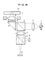
- Fig. 14 shows an example of a well known optical pickup of this type (Japanese Patent Unexamined Publication No. 61-59630).
- the optical pickup includes a light source 1 for irradiating linear polarization beam, a collimator lens 2, a beam splitter 3, an upwardly reflecting mirror 4, a 1/4 wavelength plate 5, an objective lens 6, a focusing lens 7, a half reflective mirror (hereinafter referred to a half mirror) 8, and two detectors 9 and 10.
- the linear polarization beam (p-polarization) emitted from the light source 1 is rectified into a parallel light beam flux by the collimator lens 2.
- the optical path is curved in a direction vertical to a recording surface 11a of an optical medium 11.
- the parallel optical flux reflected by the upwardly reflecting mirror 4 is converted into a circular beam by a 1/4 wavelength plate 5 and is focused on the recording surface 11a of the optical recording medium 11 through the objective lens.
- the reflected light from the recording surface 11a is returned back to the beam splitter 3 through the objective lens 6, the 1/4 wavelength plate 5 and the upwardly reflecting mirror 4.
- the reflected light is converted into a linear polarization beam (s-polarization) when the reflected light has passed through the 1/4 wavelength plate 5. Since the beam splitter has a function to pass the p-polarization light but to reflect the s-polarization light, the optical path of the reflected light returned back to the beam splitter 3 is curved toward a converging or focusing lens 7.
- the reflected light converged by the converging lens 7 is split into two beams which will be introduced into the two detectors 9 and 10 disposed in the respective optical paths, respectively.
- the optical pickup equipped with the above-described optical system has the following characteristics. Since the collimator lens 2 is interposed between the light source 1 and the beam splitter 3, an astigmatism is hardly generated. It is also possible to readily obtain a circular optical spot by disposing the beam rectifying prism or the like in the optical path from the collimator lens 2 to the objective lens 6.
- the reflective optical system needs the focusing lens 7 and the half mirror 8.
- the focusing lens 7 and the half mirror 8 must be disposed perpendicularly to the incidental optical system.
- the detectors 9 and 10 must be disposed in the two optical paths divided in the perpendicular directions to each other by the half mirror 7.
- an object of the invention is to provide a small-size optical recording medium driving apparatus.
- an optical recording medium driving apparatus which is characterized in that two beam-separation surfaces of a beam splitter are formed in an optical path of a divergent beam flex from a light source to an objective lens; and two detectors are disposed corresponding to the respective beam separation surfaces of the beam splitter so that a first one of the two separated beam fluxes of the convergent reflective beam from reflective surface of a recording layer in the recording medium is focused at a position before the associated one of the two detectors, whereas a second one of the separated beam flux is focused converged toward a position behind a second one of the two detectors, the two detectors disposed to receive substantially some intensity of beam fluxes with each other.
- the composite beam splitter having the two beam separation surfaces is disposed in the optical path of a divergent beam flux from the light source to the objective lens. It is possible to pick up signals from the respective beam separation surfaces without provision of any discrete half mirror. Thus, it is possible to reduce the number of the optical components.
- the focusing lens and the half mirror may be dispensed with, it is possible to shorten the reflective optical path from the composite beam splitter to the detectors to a minimum extent.
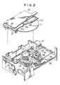
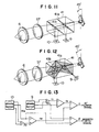
- the optical disc driver includes a housing case 22 for holding therein an optical disc 21 which is a signal recording medium, a turntable 23 for drivingly rotating the optical disc 21, and an optical pickup 24 for projecting a light beam against the optical disc 21 and detecting the reflective light thereof.
- These components 21 to 24 are mounted on a base body 26 having a disc cartridge insertion hole 25 in its front face.
- the housing case 22 is substantially in the form of a box into which insertable is a disc cartridge 27 rotatably receiving the optical disc 21.
- An opening 28 is formed in the housing case 22 in a position corresponding to the disc cartridge insertion hole 25.
- the disc cartridge 27 has a through hole 27a and a head insertion hole 27b.
- a hub 29 is fixed to a central portion of the optical disc 21 and is exposed to the outside through the through hole 27a.
- a window hole (not shown) having substantially the same configuration as that of the through hole 27a and the head insertion hole 27b.
- the housing case 22 is mounted movably up and down in an upper portion of the base body 26. When the housing case 22 is located at the uppermost position, the opening 28 is aligned with the disc cartridge insertion hole 25, whereas when the housing case 22 is located at the lowermost position, the optical disc 21 is located on the turntable 23 as described later.
- a spindle 31 coupled to a motor 30 is projected through an upper surface of the turntable 23.
- a plurality of magnets 32 are mounted around the spindle 31 for clamping the optical disc 21.
- the optical pickup 24 is composed of an objective lens 33, a swing arm 34, a upwardly reflecting mirror 35, and other various optical components (not shown) that are needed to write a signal onto the optical disc 21 and to read out the signal recorded on the optical disc 21.
- the optical pickup 24 is mounted on a carriage 36 and is moved by a motor 37. More specifically, the carriage 36 is movably mounted on a pair of guide rails 38 arranged in parallel to each other. The driving rotation of the motor 37 causes the objective lens 33 to move in the radial direction of the optical disc 21 by a distance in proportion to the angular movement of the motor 37.
- the optical disc driving apparatus will operate as follows.
- the housing case 22 is moved downwardly by a loading means (not shown) with the spindle 31 being inserted into a center hole 29a of the hun 29 mounted on the optical disc 21, thereby performing the centering operation of the optical disc 21.
- the magnets 32 mounted on the turntable 23 are operated to magnetically attract the hub 29 mounted on the central portion of the optical disc 21, thus performing the clamping operation of the optical disc 21.
- the motor 37 is driven to move the optical pickup 24 along the guide rails 38.
- the objective lens 33 is roughly tracked to the assigned address.
- the swing arm 34 is driven to thereby perform a fine tracking operation.
- the present invention is directed to the structure of the above-described optical pickup 24.
- optical pickup according to the invention will hereinafter be described in more detail.
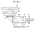
- Fig. 1 shows an optical circuit for an optical pickup in accordance with a first embodiment of the invention.
- the optical pickup includes a composition beam splitter 41, a detector base 42, and a focus actuator 43 for an objective lens 6.
- Fig. 1 the same reference numerals as those in Fig. 14 are used to indicate the like components or members.
- the composite beam splitter 41 As shown in Fig. 1, in the optical pickup according to the first embodiment, there are arranged the composite beam splitter 41, the upwardly reflecting mirror 4, and the 1/4 wavelength plate 5 in the order from the light source 1 in the optical path of divergent beam flux from the light source 1 to the objective lens 6.
- Two detectors 9 and 10 are juxtaposed on one side of the composite beam splitter 41.
- a means for emitting a coherent light such as a semiconductor laser source is used as the light source 1.
- the composite beam splitter 41 has two light separation surfaces 41a and 41b which are different from each other in light separation property.
- the first light separation surface 41a, disposed in close proximity to the light source 1, of the two light separation surfaces 41a and 41b is made of a reflecting film in which transparency for p-polarization beam is 100% and reflectivity for s-polarization beam is 100%.
- the second light separation surface 41b disposed in close proximity to the upwardly reflecting mirror 5 is made of a reflecting film in which transparency for p-polarization beam is 100% and reflectivity for s-polarization beam is 50%.
- the detectors 9 and 10 are juxtaposed on the detector plate 42.
- a first convergent beam from the first beam separation surface 41a is focused to a point before the first detector 9 and introduced into the first detector 9 in the form of divergent beam, whereas a second beam from the second beam separation surface 41b which is converged to a point behind the second detector 10 is introduced into the second detector 10.
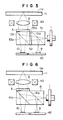
- Fig. 3 shows a first example of the detector structure, in which so-called prewove ring pits are formed in the optical recording medium, and no means for detecting the tracking signal is formed in the detectors.
- each of the detectors 9 and 10 is divided into three parts.
- a differential signal g of addition signals f1 and f2 of outer parts of the respective detectors 9 and 10 is picked up to thereby obtain a forcus error.
- the focus actuator 43 is driven.
- a differential signal h of central parts of the respective detectors 9 and 10 to thereby obtain a data signal.
- Fig. 4 shows a second example of the detector structure, in which so-called pregrooves are formed in the optical recording medium and tracking signals read out from the pregrooves are detected by the detectors.
- each of the detectors 9 and 10 is divided into four parts.
- a differential signal g of addition signals f1 and f2 of the outer parts of the respective detectors 9 and 10 is picked up to thereby obtain a focus error signal.
- an addition signal i of the central parts of the first detector 9 to obtain a data signal.
- an addition signal j of central parts of the second detector 10 is picked up to thereby obtain a tracking signal.
- the divergent beam flux 44 is directly introduced from the light source 1 into the composite beam splitter 41.
- the divergent beam flux 44 emitted from the composite beam splitter 41 is curved in a direction perpendicular to the recording surface 11a of the optical recording medium 11 by the upwardly reflecting mirror 4.
- the beam 44 is converted into a circular polarization beam by the 1/4 wavelength plate 5 and is focused onto the recording surface 11a of the optical recording medium 11 through the objective lens 6.
- the reflective beam from the recording surface 11a is returned back to the composite beam splitter 41 through the objective lens 6, the 1/4 wavelength plate 5 and the upwardly reflecting mirror 4.
- the resultant reflective light is converted into a linear polarization beam (s-polarization) when it has passed through the 1/4 wavelength plate 5. Since the second beam separation surface 41, arranged closer to the upwardly reflecting mirror 4, of the two beam separation surfaces formed in the composite beam splitter 41 is adjusted so that its reflectivity for s-polarization is at 50%, approximately 50% of the reflective beam is introduced into the second detector 10.
- the reflective beam (s-polarization) transparent through the second beam separation surface 41b is reflected by the first beam separation surface 41a arranged closer to the light source and is introduced into the first detector 9.
- the data signal, automatic focus signal and tracking signal may be detected (see Figs. 3 and 4).
- the reflective beam returned back to the composite beam splitter 41 is convergent so that any convergent lens may be dispensed with in the reflective optical system.
- the two beam separation surfaces 41a and 41b having different beam separation properties are arranged in the optical path from the light source 1 to the objective lens 6, it is possible to pick up necessary signals by using the reflective beam fluxes of the respective beam separation surfaces 41a and 41b.
- a half-transparent mirror may be dispensed with.
- the directions of the two beam separation surfaces 41a and 41b formed in the beam splitter 41 are parallel to each other, it is possible to identify the directions of the reflected lights from the composite beam splitter 41 with each other. Thus, it is possible to compose the two detectors on the single base plate 42.
- the optical pickup according to the second embodiment is composed of a first beam splitter 51, a 1/2 wavelength plate 52, a second beam splitter 53 and a 1/4 wavelength plate 5 in order from the light source 1 on the optical path of a divergent beam flux extending from the light source 1 to the objective lens 6 as shown in Fig. 5.
- the first beam splitter 51, the 1/2 wavelength plate 52 and the second beam splitter 53 may be integrally cemented together but may be formed in discrete components.
- the 1/4 wavelength plate 5 may be cemented to these components but may be formed in a discrete component.
- the beam separation surface 51a of the first beam splitter 51 is made of a reflecting film in which the transparency for p-polarization is 100% and the reflectivity for s-polarization is 100%.
- the beam separation surface 52a of the second beam splitter 52 is made of a reflecting film in which the transparency for p-polarization is 50% and the reflectivity for s-polarization is 100%.
- the two beam separation surfaces 51a and 52a are in parallel to each other and are inclined at an angle of 45 degrees with respect to the optical axis.
- the divergent beam flux (p-polarization) emitted from the light source 1 is passed through the beam splitter 51. Thereafter, its polarization plate is rotated to form the s-polarization by the 1/2 wavelength plate 52.
- the beam is introduced into the second beam splitter 53.
- the optical path of the s-polarization beam is deflected toward the 1/4 wavelength plate 5.
- the beam is converted into a circular polarization beam by the 1/4 wavelength plate 5 and is focused on the recording surface 11a of the optical recording medium 11 through the objective lens 6.
- the reflective light from the recording surface 11a is returned back to the second beam splitter 53 through the objective lens 6 and 1/4 wavelength plate 5.
- the reflective light is converted into a linear polarization beam (p-polarization) when the beam passes through the 1/4 wavelength plate 5. Since the reflectivity for p-polarization in the beam separation surface 53a of the second beam splitter 53 is adjusted to 50%, approximately 50% of the reflective beam is introduced into the second detector 10. On the other hand, the reflective light reflected at the beam separation surface 53a of the second beam splitter 53 is converted into a s-polarization beam through the 1/2 wavelength plate 52 and is introduced into the first beam splitter 51.
- the reflectivity for s-polarization in the beam separation surface 51a of the first beam splitter is set at 100%, the reflective beam that has passed through the second beam splitter 53 is reflected at the beam separation surface 51a of the first beam splitter 51 and is introduced into the first detector 9.
- the 1/2 wavelength plate 52 must be provided in addition to the system of the first embodiment but the upwardly reflecting mirror 4 may be dispensed with. This is advantageous for miniaturization of the system.
- FIG. 6 A third embodiment of the invention will now be described with reference to Fig. 6 in which the same reference numerals as those shown in Fig. 1 are used to indicate the like components or members.
- the optical pickup according to the third embodiment is composed of a composite beam splitter 41, and a 1/4 wavelength plate 5 in order from the light source 1 on the optical path extending from the light source 1 to the objective lens 6 as shown in Fig. 6.
- Detectors 9 and 10 are disposed on one side of the composite beam splitter 41.
- the composite beam splitter 41 and the 1/4 wavelength plate 5 are cemented together.
- the first beam separation surface 41a arranged closer to the light source 1 is made of a reflecting film in which the transparency for p-polarization is 100% and the reflectivity for s-polarization is 100%.
- the second beam separation surface 41b is made of a reflecting film in which the transparency for p-polarization is 50% and the reflectivity for s-polarization is 50%.
- the two beam separation surfaces 41a and 41a are formed in parallel to each other and are inclined at an angle of 45 degrees relative to the optical axis.
- the number of the optical components which are interposed between the light source 1 and the objective lens 5 is small, i.e., just two. This arrangement is very effective for reduction in weight and miniaturization of the system.
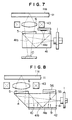
- FIG. 7 A fourth embodiment of the invention will now be described with reference to Fig. 7 in which the same reference numerals as those shown in Fig. 1 are used to indicate the like components or members.
- the optical pickup according to the fourth embodiment is composed of a composite beam splitter 41 and a 1/4 wavelength plate 5 in order from the light source 1 on the optical path extending from the light source 1 to the objective lens 6.
- the first beam separation surface 41a disposed closer to the light source 1 and the second beam separation surface 41b disposed closer to the 1/4 wavelength plate 5 are perpendicular to each other.
- Two detectors 9 and 10 are arranged on reflective optical paths of the beam separation surfaces 41a and 41b, respectively.
- the first beam separation surface 41a disposed closer to the light source 1 is made of a reflecting film in which the transparency for p-polarization is 100% and the reflectivity for s-polarization is 100%.
- the second beam separation surface 41b disposed closer to the 1/4 wavelength plate 5 is made of a reflecting film in which the transparency for p-polarization is 50% and the reflectivity for s-polarization is 50%.
- the optical pickup according to the fourth embodiment is particularly effective for reduction in weight and miniaturization of the system like the third embodiment.
- FIG. 8 A fifth embodiment of the invention will now be described with reference to Fig. 8, in which the same reference numerals as those used in Fig. 1 are used to indicate the like components or members.
- the optical pickup according to the fifth embodiment is composed of a composite beam splitter 41, an upwardly reflecting mirror 4 and a first 1/4 wavelength plate 5 in order from the light source 1 on the optical path extending from the light source 1 to the objective lens 6.
- a reflecting mirror 56 is disposed through a second 1/4 wavelength plate 55 on the reflective side of the composite beam splitter 41.
- Two detectors 9 and 10 are disposed on the side opposite the reflective mirror 56. These components 41, 4, 5, 55 and 56 are cemented in unison with each other.
- a first beam separation surface 41a disposed closer to the light source 1 is made of a reflecting film in which the transparency for p-polarization is 100% and the reflectivity for s-polarization is 100%.
- a second beam separation surface 41b disposed closer to the upwardly reflecting mirror 4 is made of a reflecting film in which the transparency for p-polarization is 100% and the reflectivity for s-polarization is 50%.
- the divergent beam flux (p-polarization) emitted from the light source 1 is passed through the composite beam splitter 41 and thereafter its optical path is deflected toward the 1/4 wavelength plate 5 by the upwardly reflecting mirror 4.
- the p-polarization beam is converted into a circular polarization beam by the 1/4 wavelength plate 5 and is focused on the recording surface 11a of the optical recording medium 11.
- the reflective beam from the recording surface 11a is returned back to the composite beam splitter 41 through the objective lens 6, the first 1/4 wavelength plate 5 and the upwardly reflecting mirror 4.
- the reflective beam is converted into a linear polarization beam (s-polarization) when it has passed through the first 1/4 wavelength plate 5. Since the s-polarization reflectivity of the second beam splitter separation surface 41b, disposed closer to the upwardly reflecting mirror 4, of the two beam separation surfaces 41a and 41b formed in the composite beam splitter 41 is adjusted to 50%, approximately 50% of reflective beam is introduced into the detector 10.
- the reflective beam (s-polarization) transparent through the second beam separation surface 41b is totally reflected at the first beam separation surface 41a since the first beam separation surface 41a is adjusted so as to reflect the s-polarization beam by 100%. Its optical path is reflected toward the reflective mirror 56.
- the reflective beam deflected toward the reflective mirror 56 is passed through the second 1/4 wavelength plate 55 and is converted into the p-polarization beam.
- the beam is then reflected toward the detector 9 by the reflective mirror 56. Since the first beam separation surface 41a is adjusted so as to pass the p-polarization beam by 100%, the reflective beam from the reflective mirror 56 is introduced into the first detector 9.
- the number of the optical parts is increased but the components except for the light source 1 and the objective lens 6 may be integrally formed. It is thus possible to make the system small in size in comparison with the conventional system.
- FIG. 9 A sixth embodiment of the invention will now be described with reference to Fig. 9 in which the same reference numerals as those in Fig. 1 are used to indicate the like members of components.
- the optical pickup according to the sixth embodiment is composed of a composite beam splitter 41, a collimator lens 57, and a 1/4 wavelength plate 5 in order from the light source 1 on the optical path extending from the light source 1 to the objective lens 6.
- Two detectors 9 and 10 are arranged on one side of the composite beam splitter 41.
- a first beam separation surface 41a, disposed closer to the light source 1, of two beam separation surfaces 41a and 41b formed in the composite beam splitter 41 is made of a reflecting film in which the transparency for p-polarization is 100% and the reflectivity for s-polarization is 100%.
- a second beam separation surface 41b disposed closer to the collimator lens 57 is made of a reflecting film in which the transparency for p-polarization is 100% and the reflectivity for s-polarization is 50%.
- These two beam separation surfaces 41a and 41b are both inclined at an angle of 45 degrees relative to the optical axis and are in parallel with each other.
- the divergent beam flux (p-polarization) emitted from the light source 1 is transmitted through the composite beam splitter 41, and thereafter is formed in a parallel beam flux by the collimator lens 57.
- the beam is converted into a circular polarization beam through the 1/4 wavelength plate 5 and is focused on the recording surface 11a of the optical recording medium 11.
- the reflective beam from the recording surface 11a is returned back to the composite beam splitter 41 through the objective lens 6, the 1/4 wavelength plate 5 and the collimator lens 57.
- the beam returned back to the composite beam splitter 41 is formed in a convergent beam by the collimator lens 57.
- the reflective beam from the recording surface 11a is converted into a linear polarization beam (s-polarization) when it has passed through the 1/4 wavelength plate 5.
- the second beam separation surface 41b disposed closer to the collimator lens 57, of the two beam separation surfaces 41a and 41b formed in the composite beam splitter 41 is adjusted so that its reflectivity for s-polarization is at about 50%, approximately 50% of the reflective beam is introduced into the detector 10.
- the reflective beam transparent through the second beam separation surface 41b is totally reflected at the first beam separation surface 41a is adjusted so that its s-polarization beam is reflected by 100%. Then, the beam is introduced into the first detector 9.
- the two detectors 9 and 10 may be disposed close to the composite beam splitter 41 and the two detectors 9 and 10 may be integrally formed with each other, it is possible to miniaturize the system in comparison with the conventional system.
- FIG. 10 A seventh embodiment of the invention will now be described with reference to Fig. 10 in which the same reference numerals as those shown in Fig. 1 are used to indicate the like members or components.
- the optical pickup according to the seventh embodiment is composed of a relay lens 59 for reducing the divergent angle of the emitted beam, a composite beam splitter 41, an upwardly reflecting mirror 5 and a 1/4 wavelength plate 6 in order from the light source 1 on the optical path extending from the light source 1 to the objective lens 6.
- the relay lens 59 may be provided in the optical pickup systems according to the second through sixth embodiments.
- the optical pickup according to the eighth embodiment is composed of a composite beam splitter 41 and a collimator lens 57 in order from the light source 1 on the optical path extending from the light source 1 to the objective lens 6.
- two detectors 9 and 10 are juxtaposed on one side of the composite beam splitter 41.
- the light source 1 is set to that the polarization plate emitted from the light source 1 is rotated at an angle of 45 degrees on the light axis relative to the parallel plane of said composite beam splitter on the polarization plane is unclined at an angle of 45 degrees relative to the upper or lower surface of the composite beam splitter 41, or at an angle of 45 degrees relative to the paper surface of Fig. 11.
- the first beam separation surface 41a, disposed closer to the light source 1, of the two beam separation surfaces of the composite beam splitter 41 is made of a reflecting film in which the transparency for p-polarization is 100% and the reflectivity for s-polarization is 50%.
- the second beam separation surface 41b disposed closer to the collimator lens 57 is made of a reflecting film in which the p-polarization reflectivity is 50% and the s-polarization transparency is 100%.
- the two beam separation surfaces 41a and 41b are inclined relative to the optical axis but are in parallel with each other.
- Fig. 13 shows a signal detection system composed of the above-described two detectors 9 and 10. As shown in Fig. 13, each of the two detectors 9 and 10 is divided into three parts. A differential signal n1 between an addition signal l1 of the outer parts of the first detector 9 and a signal representative of the central part of the first detector 9 as well as a differential signal n2 between an addition signal l2 of the outer parts of the second detector 10 and a signal representative of the center part of the second detector 10 is picked up. Then, a differential signal (n1-n2) of these signals is picked up to thereby read out the automatic focus error signal. Also, a differential signal (m1-m2) between a signal m1 of the center part of the first detector 9 and a signal m2 representative of the center part of the second detector 10 is picked up to thereby read out the data signal.
- the divergent beam flux emitted from the light source 1 is passed through the composite beam splitter 41. Thereafter, the beam is formed in a parallel beam flux by the collimator lens 57 and is focused on the recording surface 11a of the optical recording medium 11 through the objective lens 6.
- the reflective beam from the recording surface 11a is returned back to the composite beam splitter 41 through the objective lens 6 and the collimator lens 57. Since the second beam separation surface 41b is adjusted so that the p-polarization reflectivity is at 50% as described above, about 50% of the p-polarization component contained in the reflective beam is reflected by the second beam separation surface 41b and is introduced into the second detector 10. On the other hand, since the first beam separation surface 41a is adjusted so that its s-polarization reflectivity is at 50%, about 50% of the s-polarization component contained in the reflective beam transparent through the second beam separation surface 41b is reflected by the first beam separation surface 41a and is introduced into the first detector 9.
- the optical pickup according to the eighth embodiment is applicable to the magnetooptical recording medium driving apparatus. It is apparent that the optical pickup is advantageous in that the miniaturization of the system may be attained because the converging lens and the half mirror may be dispensed with unlike the conventional system.
- FIG. 12 A ninth embodiment of the invention will now be described with reference to Fig. 12 in which the same reference numerals as those shown in Fig. 1 are used to denote the like components or members.
- the optical pickup according to the ninth embodiment is composed of a composite beam splitter 41 and a collimator lens in order from the light source 1 on the optical path of a divergent beam flux extending from the light source 1 to the objective lens 6 in the same manner as in the eighth embodiment.
- the difference between the ninth embodiment and the eighth embodiment resides in the structure of the two beam separation surfaces formed in the composite beam splitter 41 and the arrangement of the detectors 9 and 10. More specifically, in the ninth embodiment, the first beam separation surface 41a disposed closer to the light source 1 and the second beam separation surface 41b disposed closer to the collimator lens 57 are each made of a reflecting film such that the p-polarization transparency is 100% and the s-polarization reflectivity is 50%.
- the two beam separation surfaces 41a and 41b are both inclined at an angle of 45 degrees relative to the optical axis and are perpendicular to each other.
- the first beam separation surface 41a disposed closer to the light source 1 is formed so that the reflective beam from the optical recording medium 11 is reflected toward the side surface of the composite beam splitter 41, whereas the second beam separation surface 41b disposed closer to the collimator lens 57 is formed so that the reflective beam from the optical recording medium 11 is transmitted downwardly of the composite beam splitter 41.
- the first detector 9 is arranged in the lateral or side direction of the composite beam splitter 41 and the second detector 10 is arranged downwardly of the composite beam splitter 41.
- the optical pickup according to the ninth embodiment has the same effect as that of the optical pickup according to the eighth embodiment.
- optical disc driving apparatus is exemplified in the respective embodiments of the invention, the essence of the invention is not limited thereby or thereto.
- the invention may be applied to any optical recording medium driving apparatus such as an optical card recording medium.
- the driving apparatus for driving the optical recording medium of the rewrite type or the recordable type with the recording medium is exemplified in the respective embodiments of the invention, the invention is applicable also to the driving apparatus for driving the optical recording medium of the reproduction-only type with reflecting layer instead of the recording layer.
- the conventional objective lens i.e., spherical lens
- an aspherical lens as the objective lens in order to improve the aberration.
- the divergent beam flux is introduced into the objective lens through the composite beam splitter having the two beam separation surfaces, the reflective beam that has been returned back into the composite beam splitter is convergent, to thereby dispense with the convergent lens and half mirror in the reflective optical system.
- the convergent lens and the half mirror are not needed in the reflective optical system, it is possible to shorten the distance from the composite beam splitter to the detectors. In view of this point, it is possible to make the optical pickup compact.
Landscapes
- Physics & Mathematics (AREA)
- Optics & Photonics (AREA)
- Optical Head (AREA)
Priority Applications (1)
| Application Number | Priority Date | Filing Date | Title |
|---|---|---|---|
| EP90300896A EP0439876A1 (de) | 1990-01-29 | 1990-01-29 | Optischer Kopf mit doppeltem Strahlteiler |
Applications Claiming Priority (1)
| Application Number | Priority Date | Filing Date | Title |
|---|---|---|---|
| EP90300896A EP0439876A1 (de) | 1990-01-29 | 1990-01-29 | Optischer Kopf mit doppeltem Strahlteiler |
Publications (1)
| Publication Number | Publication Date |
|---|---|
| EP0439876A1 true EP0439876A1 (de) | 1991-08-07 |
Family
ID=8205278
Family Applications (1)
| Application Number | Title | Priority Date | Filing Date |
|---|---|---|---|
| EP90300896A Withdrawn EP0439876A1 (de) | 1990-01-29 | 1990-01-29 | Optischer Kopf mit doppeltem Strahlteiler |
Country Status (1)
| Country | Link |
|---|---|
| EP (1) | EP0439876A1 (de) |
Cited By (11)
| Publication number | Priority date | Publication date | Assignee | Title |
|---|---|---|---|---|
| EP0537787A2 (de) * | 1991-10-18 | 1993-04-21 | Sony Corporation | Optisches Abtastgerät |
| EP0550036A2 (de) * | 1991-12-27 | 1993-07-07 | Sony Corporation | Optisches Gerät |
| EP0601567A2 (de) * | 1992-12-08 | 1994-06-15 | Sony Corporation | Optische Abtastvorrichtung für ein magneto-optisches Aufzeichnungs- und Wiedergabesystem |
| US5513158A (en) * | 1991-11-20 | 1996-04-30 | Sony Corporation | Optical disk pickup device with focusing correction by electrostriction |
| US5526330A (en) * | 1992-12-24 | 1996-06-11 | Matsushita Electric Industrial Co., Ltd. | Optical head assembly for optical information player |
| EP0723263A1 (de) * | 1995-01-13 | 1996-07-24 | Goldstar Co. Ltd. | Optisches Abtastgerät für eine magnetooptische Platte |
| US5787060A (en) * | 1993-04-27 | 1998-07-28 | Canon Kabushiki Kaisha | Optical data recording/reproducing apparatus for producing data and servo signals using different light receiving areas of a light receiver |
| EP0953859A2 (de) * | 1998-04-22 | 1999-11-03 | Nec Corporation | Fokusdetektion mittels zweier Spaltsensoren an verschiedenen Stellen entlang der optischen Achse |
| US6021105A (en) * | 1996-10-28 | 2000-02-01 | Daewoo Electronics Co., Ltd. | Knife edge method for use in an optical pickup system |
| EP1304586A3 (de) * | 2001-10-19 | 2004-01-07 | Matsushita Electric Industrial Co., Ltd. | Optisches Element, Herstellungsverfahren für dieses optische Element und dieses verwendender optischer Kopf |
| CN111508533A (zh) * | 2019-01-30 | 2020-08-07 | 中国科学院上海高等研究院 | 基于纳米光刻光盘及其物理存储介质结构和写入读出方法 |
Citations (3)
| Publication number | Priority date | Publication date | Assignee | Title |
|---|---|---|---|---|
| FR2459991A1 (fr) * | 1979-06-25 | 1981-01-16 | Olympus Optical Co | Procede et dispositif de detection d'un signal d'erreur de focalisation |
| EP0229035A2 (de) * | 1986-01-08 | 1987-07-15 | Victor Company Of Japan, Limited | Optische Aufnahme und/oder Wiedergabe von Informationssignalen |
| EP0331476A1 (de) * | 1988-03-03 | 1989-09-06 | Canon Kabushiki Kaisha | Magneto-optisches Informationswiedergabegerät mit polarisierendem Strahlteiler, dessen Inklination, bezüglich auf die anderen Bauteile, 45 Grad ist |
-
1990
- 1990-01-29 EP EP90300896A patent/EP0439876A1/de not_active Withdrawn
Patent Citations (3)
| Publication number | Priority date | Publication date | Assignee | Title |
|---|---|---|---|---|
| FR2459991A1 (fr) * | 1979-06-25 | 1981-01-16 | Olympus Optical Co | Procede et dispositif de detection d'un signal d'erreur de focalisation |
| EP0229035A2 (de) * | 1986-01-08 | 1987-07-15 | Victor Company Of Japan, Limited | Optische Aufnahme und/oder Wiedergabe von Informationssignalen |
| EP0331476A1 (de) * | 1988-03-03 | 1989-09-06 | Canon Kabushiki Kaisha | Magneto-optisches Informationswiedergabegerät mit polarisierendem Strahlteiler, dessen Inklination, bezüglich auf die anderen Bauteile, 45 Grad ist |
Non-Patent Citations (2)
| Title |
|---|
| PATENT ABSTRACTS OF JAPAN vol. 10, no. 149 (P-461)(2206) 30 May 1986, & JP-A-61 003330 (MATSUSHITA DENKI SANGYO K.K.) 9 January 1986, * |
| PATENT ABSTRACTS OF JAPAN vol. 7, no. 231 (P-229)() 13 October 1983, & JP-A-58 120216 (OLYMPUS KOGAKU KOGYO K.K.) 18 July 1983, * |
Cited By (25)
| Publication number | Priority date | Publication date | Assignee | Title |
|---|---|---|---|---|
| EP0537787A2 (de) * | 1991-10-18 | 1993-04-21 | Sony Corporation | Optisches Abtastgerät |
| EP0537787A3 (en) * | 1991-10-18 | 1993-09-08 | Sony Corporation | Optical pickup apparatus |
| US5428596A (en) * | 1991-10-18 | 1995-06-27 | Sony Corporation | Optical pickup apparatus |
| US5513158A (en) * | 1991-11-20 | 1996-04-30 | Sony Corporation | Optical disk pickup device with focusing correction by electrostriction |
| US5515348A (en) * | 1991-11-20 | 1996-05-07 | Sony Corporation | Optical disk pickup device with tilt compensation by electrostriction |
| EP0550036A2 (de) * | 1991-12-27 | 1993-07-07 | Sony Corporation | Optisches Gerät |
| EP0550036A3 (en) * | 1991-12-27 | 1993-09-22 | Sony Corporation | Optical apparatus |
| KR100280055B1 (ko) * | 1991-12-27 | 2001-01-15 | 이데이 노부유끼 | 광학 픽업장치 |
| US5350917A (en) * | 1991-12-27 | 1994-09-27 | Sony Corporation | Opto-magnetic recording polarization optical apparatus including a laser diode and a light absorbing film |
| KR100263863B1 (ko) * | 1991-12-27 | 2000-08-16 | 이데이 노부유끼 | 광학장치 |
| US5396061A (en) * | 1991-12-27 | 1995-03-07 | Sony Corporation | Opto-magnetic recording polarization optical apparatus having a light absorbing film and a total reflection film |
| EP0836177A1 (de) * | 1991-12-27 | 1998-04-15 | Sony Corporation | Optisches Gerät |
| US5523994A (en) * | 1992-12-08 | 1996-06-04 | Sony Corporation | Magneto-optical recording/reproducing apparatus with optical pickup device having a multi-layer dielectric film beam splitter |
| US5467336A (en) * | 1992-12-08 | 1995-11-14 | Sony Corporation | Magneto-optical recording/reproducing apparatus with optical pickup device having a multi-layer dielectric film beam splitter |
| EP0601567A3 (de) * | 1992-12-08 | 1995-01-25 | Sony Corp | Optische Abtastvorrichtung für ein magneto-optisches Aufzeichnungs- und Wiedergabesystem. |
| EP0601567A2 (de) * | 1992-12-08 | 1994-06-15 | Sony Corporation | Optische Abtastvorrichtung für ein magneto-optisches Aufzeichnungs- und Wiedergabesystem |
| US5526330A (en) * | 1992-12-24 | 1996-06-11 | Matsushita Electric Industrial Co., Ltd. | Optical head assembly for optical information player |
| US5787060A (en) * | 1993-04-27 | 1998-07-28 | Canon Kabushiki Kaisha | Optical data recording/reproducing apparatus for producing data and servo signals using different light receiving areas of a light receiver |
| EP0723263A1 (de) * | 1995-01-13 | 1996-07-24 | Goldstar Co. Ltd. | Optisches Abtastgerät für eine magnetooptische Platte |
| US6021105A (en) * | 1996-10-28 | 2000-02-01 | Daewoo Electronics Co., Ltd. | Knife edge method for use in an optical pickup system |
| EP0953859A2 (de) * | 1998-04-22 | 1999-11-03 | Nec Corporation | Fokusdetektion mittels zweier Spaltsensoren an verschiedenen Stellen entlang der optischen Achse |
| EP0953859A3 (de) * | 1998-04-22 | 2002-09-25 | Nec Corporation | Fokusdetektion mittels zweier Spaltsensoren an verschiedenen Stellen entlang der optischen Achse |
| EP1304586A3 (de) * | 2001-10-19 | 2004-01-07 | Matsushita Electric Industrial Co., Ltd. | Optisches Element, Herstellungsverfahren für dieses optische Element und dieses verwendender optischer Kopf |
| CN111508533A (zh) * | 2019-01-30 | 2020-08-07 | 中国科学院上海高等研究院 | 基于纳米光刻光盘及其物理存储介质结构和写入读出方法 |
| CN111508533B (zh) * | 2019-01-30 | 2022-08-30 | 中国科学院上海高等研究院 | 基于纳米光刻光盘及其物理存储介质结构和写入读出方法 |
Similar Documents
| Publication | Publication Date | Title |
|---|---|---|
| US4423496A (en) | Apparatus for reading and/or writing an optically readable information structure | |
| US5295125A (en) | Optical head device for recording/reproduction for recording medium using plural light spots | |
| KR100613737B1 (ko) | 집적 광학 소자 및 광학 픽업 및 광 디스크 장치 | |
| US4767921A (en) | Optical pickup device wherein the astigmatic converged beam spot is aligned along the dividing lines of the four-division photo-detector | |
| EP0439876A1 (de) | Optischer Kopf mit doppeltem Strahlteiler | |
| US4684797A (en) | Optical system and method for reducing vibration of an objective lens in an optical head assembly of an optical read/write system | |
| US4977552A (en) | Split type optical pick-up device with a tracking error detector on the moving part | |
| US7317675B2 (en) | Method of manufacturing optical head | |
| US5412634A (en) | Optical scanning device for a disc player including improved focusing apparatus | |
| JPH0737259A (ja) | 光ディスク装置の構成方法 | |
| JP2002367211A (ja) | 光学情報記録再生装置 | |
| US5172356A (en) | Separation type optical pickup device | |
| US5132959A (en) | Optical head in use with an optical recording/reproducing apparatus | |
| US5392274A (en) | Optical pickup device | |
| JPS62200541A (ja) | 情報記録再生装置 | |
| US6373811B1 (en) | Optical pick-up apparatus | |
| JPH09185843A (ja) | デュアルフォーカシング用光ピックアップ装置 | |
| JPH0281340A (ja) | 光記録媒体駆動装置 | |
| JP3006987B2 (ja) | 光ピックアップ | |
| JP2001110082A (ja) | 光学ピックアップ及び光ディスク装置 | |
| JPH05166222A (ja) | 分離型光ピックアップ装置 | |
| JPS6032141A (ja) | 光学式デイスク再生装置 | |
| JPH0750018A (ja) | 光学ヘッドおよびそれを用いた光学情報機器 | |
| JPH097192A (ja) | 光ディスク装置 | |
| JPH0573943A (ja) | 分離型光ピツクアツプ装置 |
Legal Events
| Date | Code | Title | Description |
|---|---|---|---|
| PUAI | Public reference made under article 153(3) epc to a published international application that has entered the european phase |
Free format text: ORIGINAL CODE: 0009012 |
|
| 17P | Request for examination filed |
Effective date: 19901228 |
|
| AK | Designated contracting states |
Kind code of ref document: A1 Designated state(s): FR GB NL |
|
| STAA | Information on the status of an ep patent application or granted ep patent |
Free format text: STATUS: THE APPLICATION HAS BEEN WITHDRAWN |
|
| 18W | Application withdrawn |
Withdrawal date: 19910926 |
|
| R18W | Application withdrawn (corrected) |
Effective date: 19910926 |