EP0437626A1 - Heat resistant structure and method of manufacture thereof - Google Patents
Heat resistant structure and method of manufacture thereof Download PDFInfo
- Publication number
- EP0437626A1 EP0437626A1 EP90910891A EP90910891A EP0437626A1 EP 0437626 A1 EP0437626 A1 EP 0437626A1 EP 90910891 A EP90910891 A EP 90910891A EP 90910891 A EP90910891 A EP 90910891A EP 0437626 A1 EP0437626 A1 EP 0437626A1
- Authority
- EP
- European Patent Office
- Prior art keywords
- brazing filler
- filler metal
- heat resisting
- sheet
- resisting structure
- Prior art date
- Legal status (The legal status is an assumption and is not a legal conclusion. Google has not performed a legal analysis and makes no representation as to the accuracy of the status listed.)
- Granted
Links
Images


Classifications
-
- B—PERFORMING OPERATIONS; TRANSPORTING
- B32—LAYERED PRODUCTS
- B32B—LAYERED PRODUCTS, i.e. PRODUCTS BUILT-UP OF STRATA OF FLAT OR NON-FLAT, e.g. CELLULAR OR HONEYCOMB, FORM
- B32B3/00—Layered products comprising a layer with external or internal discontinuities or unevennesses, or a layer of non-planar form; Layered products having particular features of form
- B32B3/10—Layered products comprising a layer with external or internal discontinuities or unevennesses, or a layer of non-planar form; Layered products having particular features of form characterised by a discontinuous layer, i.e. formed of separate pieces of material
- B32B3/12—Layered products comprising a layer with external or internal discontinuities or unevennesses, or a layer of non-planar form; Layered products having particular features of form characterised by a discontinuous layer, i.e. formed of separate pieces of material characterised by a layer of regularly- arranged cells, e.g. a honeycomb structure
-
- B—PERFORMING OPERATIONS; TRANSPORTING
- B21—MECHANICAL METAL-WORKING WITHOUT ESSENTIALLY REMOVING MATERIAL; PUNCHING METAL
- B21D—WORKING OR PROCESSING OF SHEET METAL OR METAL TUBES, RODS OR PROFILES WITHOUT ESSENTIALLY REMOVING MATERIAL; PUNCHING METAL
- B21D47/00—Making rigid structural elements or units, e.g. honeycomb structures
-
- B—PERFORMING OPERATIONS; TRANSPORTING
- B32—LAYERED PRODUCTS
- B32B—LAYERED PRODUCTS, i.e. PRODUCTS BUILT-UP OF STRATA OF FLAT OR NON-FLAT, e.g. CELLULAR OR HONEYCOMB, FORM
- B32B1/00—Layered products having a general shape other than plane
- B32B1/08—Tubular products
-
- B—PERFORMING OPERATIONS; TRANSPORTING
- B32—LAYERED PRODUCTS
- B32B—LAYERED PRODUCTS, i.e. PRODUCTS BUILT-UP OF STRATA OF FLAT OR NON-FLAT, e.g. CELLULAR OR HONEYCOMB, FORM
- B32B15/00—Layered products comprising a layer of metal
- B32B15/01—Layered products comprising a layer of metal all layers being exclusively metallic
-
- B—PERFORMING OPERATIONS; TRANSPORTING
- B32—LAYERED PRODUCTS
- B32B—LAYERED PRODUCTS, i.e. PRODUCTS BUILT-UP OF STRATA OF FLAT OR NON-FLAT, e.g. CELLULAR OR HONEYCOMB, FORM
- B32B15/00—Layered products comprising a layer of metal
- B32B15/18—Layered products comprising a layer of metal comprising iron or steel
-
- B—PERFORMING OPERATIONS; TRANSPORTING
- B32—LAYERED PRODUCTS
- B32B—LAYERED PRODUCTS, i.e. PRODUCTS BUILT-UP OF STRATA OF FLAT OR NON-FLAT, e.g. CELLULAR OR HONEYCOMB, FORM
- B32B3/00—Layered products comprising a layer with external or internal discontinuities or unevennesses, or a layer of non-planar form; Layered products having particular features of form
- B32B3/26—Layered products comprising a layer with external or internal discontinuities or unevennesses, or a layer of non-planar form; Layered products having particular features of form characterised by a particular shape of the outline of the cross-section of a continuous layer; characterised by a layer with cavities or internal voids ; characterised by an apertured layer
- B32B3/28—Layered products comprising a layer with external or internal discontinuities or unevennesses, or a layer of non-planar form; Layered products having particular features of form characterised by a particular shape of the outline of the cross-section of a continuous layer; characterised by a layer with cavities or internal voids ; characterised by an apertured layer characterised by a layer comprising a deformed thin sheet, i.e. the layer having its entire thickness deformed out of the plane, e.g. corrugated, crumpled
-
- F—MECHANICAL ENGINEERING; LIGHTING; HEATING; WEAPONS; BLASTING
- F01—MACHINES OR ENGINES IN GENERAL; ENGINE PLANTS IN GENERAL; STEAM ENGINES
- F01N—GAS-FLOW SILENCERS OR EXHAUST APPARATUS FOR MACHINES OR ENGINES IN GENERAL; GAS-FLOW SILENCERS OR EXHAUST APPARATUS FOR INTERNAL COMBUSTION ENGINES
- F01N3/00—Exhaust or silencing apparatus having means for purifying, rendering innocuous, or otherwise treating exhaust
- F01N3/08—Exhaust or silencing apparatus having means for purifying, rendering innocuous, or otherwise treating exhaust for rendering innocuous
- F01N3/10—Exhaust or silencing apparatus having means for purifying, rendering innocuous, or otherwise treating exhaust for rendering innocuous by thermal or catalytic conversion of noxious components of exhaust
- F01N3/24—Exhaust or silencing apparatus having means for purifying, rendering innocuous, or otherwise treating exhaust for rendering innocuous by thermal or catalytic conversion of noxious components of exhaust characterised by constructional aspects of converting apparatus
- F01N3/28—Construction of catalytic reactors
- F01N3/2803—Construction of catalytic reactors characterised by structure, by material or by manufacturing of catalyst support
- F01N3/2807—Metal other than sintered metal
- F01N3/281—Metallic honeycomb monoliths made of stacked or rolled sheets, foils or plates
-
- B—PERFORMING OPERATIONS; TRANSPORTING
- B32—LAYERED PRODUCTS
- B32B—LAYERED PRODUCTS, i.e. PRODUCTS BUILT-UP OF STRATA OF FLAT OR NON-FLAT, e.g. CELLULAR OR HONEYCOMB, FORM
- B32B2305/00—Condition, form or state of the layers or laminate
- B32B2305/02—Cellular or porous
- B32B2305/024—Honeycomb
-
- B—PERFORMING OPERATIONS; TRANSPORTING
- B32—LAYERED PRODUCTS
- B32B—LAYERED PRODUCTS, i.e. PRODUCTS BUILT-UP OF STRATA OF FLAT OR NON-FLAT, e.g. CELLULAR OR HONEYCOMB, FORM
- B32B2307/00—Properties of the layers or laminate
- B32B2307/30—Properties of the layers or laminate having particular thermal properties
- B32B2307/306—Resistant to heat
-
- B—PERFORMING OPERATIONS; TRANSPORTING
- B32—LAYERED PRODUCTS
- B32B—LAYERED PRODUCTS, i.e. PRODUCTS BUILT-UP OF STRATA OF FLAT OR NON-FLAT, e.g. CELLULAR OR HONEYCOMB, FORM
- B32B2311/00—Metals, their alloys or their compounds
- B32B2311/30—Iron, e.g. steel
-
- F—MECHANICAL ENGINEERING; LIGHTING; HEATING; WEAPONS; BLASTING
- F01—MACHINES OR ENGINES IN GENERAL; ENGINE PLANTS IN GENERAL; STEAM ENGINES
- F01N—GAS-FLOW SILENCERS OR EXHAUST APPARATUS FOR MACHINES OR ENGINES IN GENERAL; GAS-FLOW SILENCERS OR EXHAUST APPARATUS FOR INTERNAL COMBUSTION ENGINES
- F01N2330/00—Structure of catalyst support or particle filter
- F01N2330/02—Metallic plates or honeycombs, e.g. superposed or rolled-up corrugated or otherwise deformed sheet metal
- F01N2330/04—Methods of manufacturing
-
- Y—GENERAL TAGGING OF NEW TECHNOLOGICAL DEVELOPMENTS; GENERAL TAGGING OF CROSS-SECTIONAL TECHNOLOGIES SPANNING OVER SEVERAL SECTIONS OF THE IPC; TECHNICAL SUBJECTS COVERED BY FORMER USPC CROSS-REFERENCE ART COLLECTIONS [XRACs] AND DIGESTS
- Y02—TECHNOLOGIES OR APPLICATIONS FOR MITIGATION OR ADAPTATION AGAINST CLIMATE CHANGE
- Y02A—TECHNOLOGIES FOR ADAPTATION TO CLIMATE CHANGE
- Y02A50/00—TECHNOLOGIES FOR ADAPTATION TO CLIMATE CHANGE in human health protection, e.g. against extreme weather
- Y02A50/20—Air quality improvement or preservation, e.g. vehicle emission control or emission reduction by using catalytic converters
-
- Y—GENERAL TAGGING OF NEW TECHNOLOGICAL DEVELOPMENTS; GENERAL TAGGING OF CROSS-SECTIONAL TECHNOLOGIES SPANNING OVER SEVERAL SECTIONS OF THE IPC; TECHNICAL SUBJECTS COVERED BY FORMER USPC CROSS-REFERENCE ART COLLECTIONS [XRACs] AND DIGESTS
- Y10—TECHNICAL SUBJECTS COVERED BY FORMER USPC
- Y10T—TECHNICAL SUBJECTS COVERED BY FORMER US CLASSIFICATION
- Y10T428/00—Stock material or miscellaneous articles
- Y10T428/12—All metal or with adjacent metals
- Y10T428/1234—Honeycomb, or with grain orientation or elongated elements in defined angular relationship in respective components [e.g., parallel, inter- secting, etc.]
-
- Y—GENERAL TAGGING OF NEW TECHNOLOGICAL DEVELOPMENTS; GENERAL TAGGING OF CROSS-SECTIONAL TECHNOLOGIES SPANNING OVER SEVERAL SECTIONS OF THE IPC; TECHNICAL SUBJECTS COVERED BY FORMER USPC CROSS-REFERENCE ART COLLECTIONS [XRACs] AND DIGESTS
- Y10—TECHNICAL SUBJECTS COVERED BY FORMER USPC
- Y10T—TECHNICAL SUBJECTS COVERED BY FORMER US CLASSIFICATION
- Y10T428/00—Stock material or miscellaneous articles
- Y10T428/24—Structurally defined web or sheet [e.g., overall dimension, etc.]
- Y10T428/24149—Honeycomb-like
-
- Y—GENERAL TAGGING OF NEW TECHNOLOGICAL DEVELOPMENTS; GENERAL TAGGING OF CROSS-SECTIONAL TECHNOLOGIES SPANNING OVER SEVERAL SECTIONS OF THE IPC; TECHNICAL SUBJECTS COVERED BY FORMER USPC CROSS-REFERENCE ART COLLECTIONS [XRACs] AND DIGESTS
- Y10—TECHNICAL SUBJECTS COVERED BY FORMER USPC
- Y10T—TECHNICAL SUBJECTS COVERED BY FORMER US CLASSIFICATION
- Y10T428/00—Stock material or miscellaneous articles
- Y10T428/24—Structurally defined web or sheet [e.g., overall dimension, etc.]
- Y10T428/24744—Longitudinal or transverse tubular cavity or cell
Definitions
- the present invention relates to a heat resisting structure to be used at a high environmental temperature. More particularly, the present invention relates to a heat resisting structure wherein stainless steel corrugated sheets, flat sheets, etc. are joined together with brazing filler metal to form a honeycomb-like structure and it is used, for example, for a catalytic converter to treat exhaust gas of an automobile engine or the like as a catalyst holding body to which catalyst is made adhered.
- a heat resisting structure wherein stainless steel corrugated sheets having alternating ridges and grooves formed by folding the sheet continuously and flat stainless steel sheets, etc. are joined together with nickel(Ni)-base brazing filler metal to form honeycomb-like structure is conventionally used.
- stainless steel corrugated sheets, flat sheets, etc. which are highly resistant to corrosion and heat are used as base metal and nickel(Ni)-base brazing filler metal which is also highly resistant to corrosion and heat is used to withstand a high environmental temperature.
- the heat resisting structure is formed into a roll-like form by rolling up the corrugated sheet, flat sheet, etc. and joining together with nickel(Ni)-base brazing filler metal or formed into a laminated block by stacking the materials into many layers and joining together, and thus formed honeycomb-like structure is utilized as a catalyst holding body and for other various uses.
- brazing filler metal As to the corrugated sheet, flat sheet, etc. constituting the base metal, those of austenitic stainless steel are used. Recently, those of ferritic stainless steel also are in use.
- nickel(Ni)-base brazing filler metal is used generally by applying it to the entire surface.
- the brazing filler metal is provided over the entire surface between the corrugated sheet, flat sheet, etc. constituting the base metal by, for example, coating the entire surface, placing foil-like brazing filler metal between the sheets over the entire surface, or using a brazing sheet coated with brazing filler metal over the entire surfaces.
- Composition of brazing filler metal currently in use is, by weight, 0.1% C maximum, 7.0 to 8.0% silicon Si, 18.0% to 19.0% chromium Cr, 1.0 to 1.5% boron B, and the remainder is nickel Ni.
- the heat resisting structure employing austenitic stainless steel corrugated sheets, flat sheets, etc. is excellent in oxidation resistance as well as high-temperature strength to withstand a high environmental temperature during the use.
- this heat resisting structure when stress is applied during use at a high environmental temperature, stress corrosion cracks sometimes occur in the corrugated sheets, flat sheets, etc. constituting the base metal, in some cases carbide is precipitated on grain boundaries of the austenitic portion of the base metal, where intergranular corrosion cracking occurs, and thus durability of the structure at a high environmental temperature is affected.
- heat resisting structure wherein ferritic stainless steel corrugated sheets, flat sheets, etc. are used as the base metal has been developed.
- the state of elements of the alloy, so-called phase, of the corrugated sheets, flat sheets, etc. which are the base metal is different from that of nickel(Ni)-base brazing filler metal. Therefore, when nickel(Ni)-base brazing filler metal diffuses into the base metal owing to brazing for joining, the phase tends to change in the vicinity of the boundary where the base metal is joined, causing phase transition. (For example, transition to gamma phase. Hereinafter, the same applies.) Therefore, the use at a high environmental temperature is sometimes affected adversely.
- chromium Cr contained in nickel(Ni)-base brazing filler metal is segregated in the vicinity of the boundary where the base metal of, for example, ferritic stainless steel is joined by brazing, making the chromium Cr concentration very high at the portion of the metal phase, and the portion of low chromium Cr concentration is prone to oxidation.
- carbon C contained in the nickel(Ni)-base brazing filler metal is sometimes precipitated as carbide on the grain boundaries in the vicinity of the boundary where the base metal is joined by brazing. The precipitated material reduces the strength lower than the toughness. Therefore, stress corrosion cracking, intergranular corrosion cracking, intergranular separation, etc. tend to occur in the austenitized portion in a similar manner to that mentioned above. (For example, transition to gamma phase. Hereinafter, the same applies.)
- the present invention has been originally conceived in consideration of actual condition of prior art.
- the present invention relates to heat resisting structure of honeycomb-like construction wherein corrugated sheets having alternating ridges and grooves formed by folding the sheet continuously and flat sheets, etc. are joined together with brazing filler metal.
- This heat resisting structure for example, is made in a roll-like form wherein a belt-like corrugated sheet and flat sheet are alternately overlapped, rolled up, and jointed.
- this heat resisting structure for example, is made in a laminated block-like form wherein corrugated sheets of predetermined length and flat sheets are alternately and sequentially overlapped in may layers and joined.
- this heat resisting structure for example, is made in a roll-like form using a belt-like corrugated sheet only or made in the laminated block form using corrugated sheets only as the case may be.
- the first mode of this invention is a heat resisting structure, wherein the heat resisting structure is made into a roll-like form using a corrugated sheet and flat sheet or corrugated sheet only, and the corrugated sheet and flat sheet are of stainless steel and the brazing filler metal of nickel(Ni)-base brazing filler metal containing silicon Si and boron B is used as the brazing filler metal.
- the second mode of this invention is a heat resisting structure of a roll-like form using a corrugated sheet and flat sheet, wherein the corrugated sheet and flat sheet are of ferritic stainless steel, and nickel(Ni)-base brazing filler metal is used as the brazing filler metal, which is arranged at predetermined places in the joint area of the corrugated sheet and flat sheet, and the quantity of the brazing filler metal has been determined to be a rate within a range from 0.002 g to 0.07 g per 1 cc volume of the heat resisting structure.
- the manufacturing method of the heat resisting structure comprises a preparation process, brazing filler metal arranging process, forming process, joining process, etc.
- a ferritic stainless steel corrugated sheet and a ferritic stainless steel flat sheet are prepared.
- nickel(Ni)-base brazing filler metal is used with the quantity determined to be a rate within a range from 0.002 g to 0.07 g per 1 cc volume of the heat resisting structure.
- the brazing filler metal is arranged at predetermined places in the joint area between the corrugated sheet and flat sheet.
- the corrugated sheet and flat sheet are alternately rolled up so as to make a roll-like form.
- the corrugated sheet and flat sheet are joined together with brazing filler metal by heating up after above-mentioned processes.
- the third mode of this invention is a heat resisting structure of a roll or laminated block form, wherein the corrugated sheet and flat sheet are of stainless steel and the brazing filler metal is of iron(Fe)-base brazing filler metal.
- the inventions having these three modes consist of a group of interrelated inventions which form a single invention concept and exhibit the following operational effects common to these modes.
- this heat resisting structure when used at a high environmental temperature, occurrence of segregation at the vicinity of the joint boundary of the corrugated sheet, flat sheet, etc. constituting the base metal joined with brazing filler metal is reduced and consequently generation of a high chromium Cr concentration portion is reduced, as a result, occurrence of a problem that a low chromium Cr concentration portion is prone to oxidation is prevented.
- this heat resisting structure the effect of carbide precipitated in the vicinity of the joint boundary on the grain boundaries is reduced, thereby stress corrosion cracking, intergranular corrosion cracking, intergranular separation, etc. are reduced.
- this heat resisting structure is small in the oxidation rate and has improved oxidation resistance and excellent durability.
- this heat resisting structure is advantageous in the aspect of cost, because it can be manufactured with ease with least man-hours. For example, arranging the brazing filler metal and its setting are easy.
- Figs. 1 and 2 show preferred embodiments of the first mode of the heat resisting structure in accordance with the present invention, in which Fig. 1 is a perspective view of the roll-form structure and Fig. 2 is a perspective view of the laminated block-form structure.
- Fig. 3 is a graph showing the comparison of the oxidation rate between the heat resisting structure of the present invention and conventional heat resisting structure.
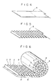
- Figs. 4 through 8 show preferred embodiments of the second mode of the heat resisting structure in accordance with the present invention, in which Fig. 4 is a perspective view of the flat sheet for explaining the preparation process of the manufacturing method, Fig. 5 is a perspective view of the corrugated sheet, Fig. 6 is a perspective view for explaining the brazing filler metal arranging process and forming process of the manufacturing method, Fig. 7 is a perspective view of a case, and Fig. 8 is a perspective view of the roll-form heat resisting structure thus manufactured.
- Fig. 9 is a graph showing the relation between the quantity of brazing filler metal and the oxidation rate.
- Fig. 10 is a graph showing relation between the quantity of brazing filler metal and the treatment rate of catalyst.
- Figs. 11 and 12 show preferred embodiments of the third mode of the heat resisting structure in accordance with the present invention, in which Fig. 11 is a perspective view of the roll-form structure and Fig. 12 is a perspective view of the laminated block-form structure.
- the heat resisting structure 1 shown in these drawings is of a honeycomb-like structure wherein a belt-like stainless steel corrugated sheet 2, etc. having alternating ridges and grooves formed by folding the sheet continuously is joined alternately via brazing filler metal 3.
- a base metal of the heat resisting structure 1 As a base metal of the heat resisting structure 1, one belt-like corrugated sheet 2 having alternating ridges and grooves formed by folding the sheet continuously and made of stainless steel foil, and one belt-like flat sheet 4 of stainless steel foil are used.
- one long sheet of such corrugated sheet 2 and one long sheet of flat sheet 4 are used.
- the corrugated sheet 2 is formed into a large number of straight ridges and grooves of predetermined pitch and height continuously and in parallel by folding the sheet by a corrugating machine, press, etc.
- the base metal of the heat resisting structure 1 may be such that more than one corrugated sheets 5 and flat sheets 4 may be used disregarding the example of Fig. 1. Further, use of one or more corrugated sheets, without using the flat sheet 4, may be feasible.
- the shape of the heat resisting structure 1 is a roll-form of a circular cylinder, elliptical cylinder, etc. wherein one corrugated sheet 2 and one flat sheet 4 are alternately lapped, rolled up, and joined starting at the center via the brazing filler metal 3.
- the shape of the heat resisting structure may be such, different from the embodiment shown in Fig. 1, that more than one plate-like corrugated sheets 2 of a predetermined length, flat sheets 4, etc. constituting the base metal are alternately and sequentially stacked in many layers and joined via brazing filler metal 3 to make a laminated block-like form as shown in Fig. 2.
- the heat resisting structure 1 is a honeycomb-like construction. That is, the base metal, i.e., in the examples of Figs. 1 and 2, the corrugated sheets 2 and flat sheets 4 form cell walls and a honeycomb-like structure which is a plane assembly of many hollow column-like cells 5 of a variety of shapes including a triangle, semihexagon, trapezoid, or the like. Accordingly, this heat resisting structure 1 has an excellent specific strength, light weight, and high rigidity and strength. It is also known to have a good flow straightening effect, easy-to-form feature, and low cost.
- the surface area per unit volume is large, in other words, the surface area of cell walls formed by the corrugated sheets 2, flat sheets 4, etc., is large, and in addition the high temperature strength is large since the corrugated sheets 2 and flat sheets 4 are made of stainless steel which is highly resistant to heat and the brazing filler metal 3 is made of nickel (Ni)-base brazing filler metal which is also highly resistant to heat. Due to such advantages, this heat resisting structure 1 is, for example, used for a catalytic converter to treat exhaust gas of an automobile engine, etc., as a catalyst holding body and catalyst is made adhered to the surface of the corrugated sheets 2 and flat sheets 4 which form the cell walls.
- nickel(Ni)-base brazing filler metal containing silicon Si and boron B is used as the brazing filler metal 3 for joining. More specifically, nickel(Ni)-base brazing filler metal composed mainly, by weight, of 4.0 to 8.0% silicon Si, 2.0 to 4.5% boron B, and the remainder nickel Ni is used as the brazing filler metal 3. Carbon C and chromium Cr are not almost contained in the main components.
- Such brazing filler metal 3 is provided at places in the joint area between the corrugated sheets 2 and flat sheets 4 which constitute the base metal, and melts when heated and brazes the joint area when hardens.
- reference number 6 designates a case which is an outer cylinder for holding an inserted roll-form heat resisting structure 1.
- the heat resisting structures 1 shown in Figs. 1 and 2 are constructed in the above-mentioned manner and used, for example, as a catalyst holding body of a catalytic converter of an automobile engine or the like. Exhaust gas of an automobile engine or the like which contains harmful substances and of a high temperature is treated by reaction of the catalyst made adhered to the corrugated sheet 2, flat sheet 4, etc. which form the cell walls while it is passing through each cell 5 of honeycomb-like structure of the heat resisting structure 1 .
- This heat resisting structure 1 uses nickel(Ni)-base brazing filler metal containing silicon Si and boron B as the brazing filler metal for joining stainless steel corrugated sheets 2 and flat sheets 4. Therefore, advantages described in (1), (2), (3) and (4) below are obtained.
- the manufacturing method of the heat resisting structure 1 shown in these drawings will be described in the sequence of the preparation process, brazing filler metal arranging process, forming process, and joining process, and then the heat resisting structure 1 will be described.
- the preparation process is as follows.
- a ferritic stainless steel corrugated sheet 2 (see Fig. 5) having alternating ridges and grooves formed by folding the sheet continuously into a belt-like form and a ferritic stainless steel flat sheet 4 (see Fig. 4) of a belt-like form are prepared.
- As raw materials of the corrugated sheet 2 and flat sheet 4 ferritic stainless steel having main components of iron Fe, 20 chrome Cr, 5 aluminum Al is used.
- One flat sheet of a belt-like and foil-like form made of material mentioned above is prepared to be used as is as the flat sheet 4.
- the corrugated sheet 2 is obtained by corrugating such raw material of foil-like flat sheet using a corrugating machine or the like, and straight ridges and grooves of a predetermined form are formed by folding the sheet continuously.
- Nickel(Ni)-base brazing filler metal is used as the brazing filler metal 7. Its quantity is set to a rate within the range from 0.002 g to 0.07 g per 1 cc volume of the heat resisting structure 1. In the brazing filler metal arranging process, such brazing filler metal 7 is arranged at a predetermined places in the joint area between the corrugated sheet 2 and flat sheet 4.
- nickel(Ni)-base brazing filler metal the main component of which is nickel Ni
- the composition of the brazing filler metal 7 is, by weight, 0.1% carbon C maximum, 7.0% to 8.0% silicon Si, 18.0 to 19.5% chromium Cr, 1.0 to 1.5% boron B, and the remainder is nickel Ni.
- the nickel(Ni)-base brazing filler metal has high high-temperature strength and excellent oxidation resistance.
- Such brazing filler metal (7) is arranged at the predetermined places in the joint area of the corrugated sheet 2 and flat sheet 4.
- the brazing filler metal 7 does not braze the entire surface as is the case with the conventional practice, i.e., it does not cover the entire surface between the corrugated sheet 2 and flat sheet 4, but is arranged only at predetermined places in the joint area.
- the brazing filler metal 7 is arranged via adhesive (not shown) applied in a variety of forms such as dots, short lines (see Fig. 6), etc. at a predetermined interval in its width direction on the outside of ridges and grooves of the corrugated sheet 2.
- the brazing filler metal 7 may be arranged in parallel-line pattern at a predetermined interval along the longitudinal direction of the corrugated sheet 2 or the like (for example, brazing filler metal formed in a line-form with narrow width) disregarding the embodiments shown in the drawings.
- the advantage is that arranging the brazing filler metal is facilitated.
- the brazing filler metal 7 is provided at predetermined places in various locations, numbers, sizes, shapes, etc.
- Quantity of the brazing filler metal to be arranged in this manner is determined to be a suitable rate within the range from 0.002 g to 0.07 g per 1 cc volume of the finished heat resisting structure 1 (refer to Fig. 9 also).
- Nickel(Ni)-base amorphous brazing filler metal may be used as the brazing filler metal 7. Since the corrugated sheet 2 and flat sheet 4 are joined strongly in this case, the particular advantage of this heat resisting structure 1 is in the high strength.
- the corrugated sheet 2 and flat sheet 4 are alternately rolled up to form a roll-like form.
- alternate rolling up of the corrugated sheet 2 and flat sheet 4 is started at the predetermined center, and lapped into many layers.
- the forming process is performed before or after the brazing filler metal arranging process, or concurrently with this process.
- the brazing filler metal 7 may be arranged at the predetermined places in the joint area in the brazing filler metal arranging process. In this case, the brazing filler metal 7 is arranged at both ends of the corrugated sheet 2 and flat sheet 4 as the predetermined places.
- the brazing filler metal 7 is arranged at the predetermined places in the joint area of the corrugated sheet 2 and flat sheet 4, these sheets may be rolled up in a roll-like form in the forming process.
- the brazing filler metal 7 formed in a line-form with narrow width may be arranged in parallel at a predetermined interval along the longitudinal direction of the corrugated sheet 2 and flat sheet 4.
- the forming process and brazing filler metal arranging process are performed concurrently and in parallel, and while rolling up the corrugated sheet 2 and flat sheet 4 in a roll-like form, the brazing filler metal 7 may be arranged sequentially at the predetermined places in the joint area as an alternative method.
- the corrugated sheet 2 and flat sheet 4 are joined with the brazing filler metal 7 by heating up. That is, the brazing filler metal 7 provided at the predetermined places in the joint area of the corrugated sheet 2 and flat sheet 4 in the brazing filler arranging process is melted by heating up and joins the sheets 2 and 4.
- the sheets 2 and 4 which have been rolled up in a roll-like form in the forming process form a honeycomb-like structure and the shape is fixed to a circular cylinder, elliptical cylinder, or other specified form.
- the heat resisting structure 1 shown in Fig. 8 is manufactured.
- the heat resisting structure 1 is a roll-like structure wherein the belt-like corrugated sheet 2 having alternating ridges and grooves formed by folding the sheet continuously and the belt-like flat sheet 4 are alternately rolled up and joined via the brazing filler metal 7, thus a honeycomb-like structure is made.
- the corrugated sheet 2 and flat sheet 4 are made of ferritic stainless steel.
- the brazing filler metal 7 is nickel(Ni)-base brazing filler metal and provided at predetermined places in the joint area of the corrugated sheets 2 and flat sheet 4.
- the quantity of the brazing filler metal 7 is determined to be a rate within the range from 0.002 g to 0.07 g per 1 cc volume of the heat resisting structure 1.
- this heat resisting structure 1 spaces of the corrugated sheet 2 are sectioned into independent vacant spaces by the flat sheet 4, and the sheets 2 and 4 form cell walls, and thus a honeycomb-like structure which is a plane assembly of hollow column-like cells 5 is formed.
- the heat resisting structure 1 of such honeycomb-like construction is known to have advantages such as high high-temperature strength, light weight, high rigidity and strength, good flow straightening effect, easy forming, low cost, etc.
- This heat resisting structure 1 is used, for example, for a catalytic converter to treat exhaust gas of an automobile engine as a catalyst holding body and the catalyst is made adhered to the surfaces of the corrugated sheet 2 and flat sheet 4.
- Figs. 7 and 8 shows a case 6 in which the heat resisting structure 1 is inserted and held.
- the heat resisting structure 1 shown in Figs. 4 through 8 is as follows.
- brazing filler metal 7 of nickel(Ni)-base brazing metal is provided at specified places in the joint area of the ferritic stainless steel corrugated sheet 2 and flat sheet 4 which are made in honeycomb-like structure by being rolled up in a roll-like form.
- the quantity of the brazing filler metal 7 is determined to be a rate within the range from 0.002 g to 0.07 g per 1 cc volume of this heat resisting structure 1.
- the manufacturing method of the heat resisting structure 1 is such that the brazing filler metal 7 of nickel(Ni)-base brazing filler metal is provided in the brazing filler metal arranging process with the quantity of a predetermined rate mentioned above at the predetermined places in the joint area of the ferritic stainless steel corrugated sheet 2 and flat sheet 4 prepared in the preparation process, and the corrugated sheet 2 and flat sheet 4 constituting the base metal are rolled up in the forming process to form a roll-like form.
- the corrugated sheet 2 and flat sheet 4 constituting the base metal are joined with the brazing filler metal 7 by heating up in the joining process, and as a result the heat resisting structure 1 of the honeycomb-like structure which is a plane assembly of hollow column-like cells 5 is manufactured.
- the heat resisting structure 1 is formed in a honeycomb-like structure wherein the corrugated sheet 2 of stainless steel having alternating ridges and grooves formed by folding the sheet continuously and the stainless steel flat sheet 4 are joined alternately via the brazing filler metal 8 which is made of iron(Fe)-base brazing filler metal.
- the corrugated sheet 2 and flat sheet 4 constituting the base metal ferritic stainless steel, austenitic stainless steel, and other various stainless steels having excellent corrosion resistance and heat resistance are used.
- foil-like flat sheet of such stainless steel is used as is as the flat sheet 4.
- the corrugate sheet 2 is obtained by corrugating the foil-like flat raw material of stainless steel by means of a corrugating machine or the like, by which alternating straight ridges and grooves of predetermined shape is formed by folding the sheet continuously.
- the brazing filler metal 8 made of iron(Fe)-base group brazing filler metal contains iron Fe as the main component, and is known by its excellent corrosion resistance and heat resistance.
- the brazing filler metal 8 is used in a variety of forms such as powder, paste, amorphous, etc.
- the roll-like (Fig. 11) or laminated block-like (Fig. 12) heat resisting structure 1 is formed using such stainless steel corrugated sheet 2, flat sheet 4, and the brazing filler metal 8 of iron(Fe)-base brazing filler metal.
- the roll-like heat resisting structure 1 shown in Fig. 11 comprises one belt-like stainless steel corrugated sheet 2 and one belt-like stainless steel flat sheet 4.
- the outline of the manufacturing method is such that first the brazing filler metal 8 of amorphous iron(Fe)-base brazing filler metal or the like is arranged, for example, over the entire surface between such corrugated sheet 2 and flat sheet 4, and then the corrugated sheet 2 and flat sheet 4 are rolled up alternately starting at the predetermined center and lapped into many layers.
- Arranging the brazing filler metal 8 and rolling up the corrugated sheet 2 and flat sheet 4 may be performed concurrently and in parallel. Thereafter, the brazing filler metal 8 is melted by heating up to join the corrugated sheet 2 and the flat sheet 4 together, and thus a predetermined roll-like (circular cylinder, elliptical cylinder, etc.) heat resisting structure 1 is fabricated.
- the laminated block-like heat resisting structure 1 shown in Fig. 12 is made of more than one stainless steel plate-form corrugated sheets 2 of predetermined length and more than one stainless steel plate-form flat sheets 4 of the same length.
- the outline of the manufacturing method is such that these corrugated sheet 2 and flat sheet 4 are alternately stacked vertically in sequence with the brazing filler metal 8 which is iron(Fe)-base brazing filler metal placed between them, for example, on the entire surface. Such placing and stacking may be performed one after another (not simultaneously and not in parallel). Thereafter, the brazing filler metal 8 is melted to join the corrugated sheet 2 and flat sheet 4 by pressing and heating up at the top and bottom faces, and the laminated block-like heat resisting structure 1 of predetermined form is manufactured.
- the heat resisting structure according to the present invention is not limited to that of the roll-form (Fig. 11) or the laminated-form (Fig. 12) but those of other various forms are possible. Furthermore, the heat resisting structure can be formed by using only corrugated sheet 2 without using the flat sheet 4.
- heat resisting structure 1 spaces of corrugated sheet 2 are sectioned into independent vacant spaces by the flat sheet 4, and the corrugated sheet 2 and flat sheet 4 form cell walls, thus a honeycomb-like structure which is a plane assembly of hollow column-like cells 5 is formed.
- Such heat resisting structure 1 of a honeycomb-like structure is known to have such advantages as a high high-temperature strength, light weight, high rigidity and strength, excellent flow straightening effect, easy-to-form feature, low cost, etc.
- heat resisting structure 1 is, for example, used for a catalytic converter for treating exhaust gas of an automobile engine as a catalyst holding body, and catalyst such as platinum Pt, palladium Pd, rhodium Rh, or the like is made adhered to the surfaces of the corrugated sheet 2 and flat sheet 4.
- the heat resisting structure 1 shown in Figs. 11 and 12 is constructed as mentioned-above, the advantages are as follows.
- the brazing filler metal 8 made of iron(Fe)-base brazing filler metal is used for joining the corrugated sheet 2 and flat sheet 4. And such heat resisting structure 1 is used at a high environmental temperature as, for example, a catalyst holding body. Its advantages are as described in (1) through (7) below.
- the heat resisting structure in accordance with the present invention is suitable for use at a high environmental temperature, and actually it is used for a variety of uses.
- it is used for a catalytic converter for treatment of exhaust gas of an automobile engine as a catalyst holding body, to which the catalyst is made adhered.
Abstract

Description
- The present invention relates to a heat resisting structure to be used at a high environmental temperature. More particularly, the present invention relates to a heat resisting structure wherein stainless steel corrugated sheets, flat sheets, etc. are joined together with brazing filler metal to form a honeycomb-like structure and it is used, for example, for a catalytic converter to treat exhaust gas of an automobile engine or the like as a catalyst holding body to which catalyst is made adhered.
- A heat resisting structure wherein stainless steel corrugated sheets having alternating ridges and grooves formed by folding the sheet continuously and flat stainless steel sheets, etc. are joined together with nickel(Ni)-base brazing filler metal to form honeycomb-like structure is conventionally used. In such a conventional heat resisting structure, stainless steel corrugated sheets, flat sheets, etc. which are highly resistant to corrosion and heat are used as base metal and nickel(Ni)-base brazing filler metal which is also highly resistant to corrosion and heat is used to withstand a high environmental temperature. The heat resisting structure is formed into a roll-like form by rolling up the corrugated sheet, flat sheet, etc. and joining together with nickel(Ni)-base brazing filler metal or formed into a laminated block by stacking the materials into many layers and joining together, and thus formed honeycomb-like structure is utilized as a catalyst holding body and for other various uses.
- Now, relating to the corrugated sheet, flat sheet, brazing filler metal, etc. of the heat resisting structure, prior art will be examined in detail. First, as to the corrugated sheet, flat sheet, etc. constituting the base metal, those of austenitic stainless steel are used. Recently, those of ferritic stainless steel also are in use. As to the brazing filler metal, nickel(Ni)-base brazing filler metal is used generally by applying it to the entire surface. The brazing filler metal is provided over the entire surface between the corrugated sheet, flat sheet, etc. constituting the base metal by, for example, coating the entire surface, placing foil-like brazing filler metal between the sheets over the entire surface, or using a brazing sheet coated with brazing filler metal over the entire surfaces. Composition of brazing filler metal currently in use is, by weight, 0.1% C maximum, 7.0 to 8.0% silicon Si, 18.0% to 19.0% chromium Cr, 1.0 to 1.5% boron B, and the remainder is nickel Ni.
- However, the following problems have been pointed out concerning the above-mentioned conventional heat resisting structure.
- First, the heat resisting structure employing austenitic stainless steel corrugated sheets, flat sheets, etc. is excellent in oxidation resistance as well as high-temperature strength to withstand a high environmental temperature during the use. However, this heat resisting structure, when stress is applied during use at a high environmental temperature, stress corrosion cracks sometimes occur in the corrugated sheets, flat sheets, etc. constituting the base metal, in some cases carbide is precipitated on grain boundaries of the austenitic portion of the base metal, where intergranular corrosion cracking occurs, and thus durability of the structure at a high environmental temperature is affected. In addition, there is a problem in cost due to expensiveness of the material. To solve the problems in the heat resisting structure of austenitic stainless steel mentioned above, heat resisting structure wherein ferritic stainless steel corrugated sheets, flat sheets, etc. are used as the base metal has been developed.
- Secondly, in the heat resisting structure employing stainless steel, particularly ferritic stainless steel corrugated sheets, flat sheets, etc., the state of elements of the alloy, so-called phase, of the corrugated sheets, flat sheets, etc. which are the base metal is different from that of nickel(Ni)-base brazing filler metal. Therefore, when nickel(Ni)-base brazing filler metal diffuses into the base metal owing to brazing for joining, the phase tends to change in the vicinity of the boundary where the base metal is joined, causing phase transition. (For example, transition to gamma phase. Hereinafter, the same applies.) Therefore, the use at a high environmental temperature is sometimes affected adversely. More specifically, when such conventional heat resisting structure is used at a high environmental temperature, chromium Cr contained in nickel(Ni)-base brazing filler metal is segregated in the vicinity of the boundary where the base metal of, for example, ferritic stainless steel is joined by brazing, making the chromium Cr concentration very high at the portion of the metal phase, and the portion of low chromium Cr concentration is prone to oxidation. Further, when the conventional heat resisting structure is used at a high environmental temperature, carbon C contained in the nickel(Ni)-base brazing filler metal is sometimes precipitated as carbide on the grain boundaries in the vicinity of the boundary where the base metal is joined by brazing. The precipitated material reduces the strength lower than the toughness. Therefore, stress corrosion cracking, intergranular corrosion cracking, intergranular separation, etc. tend to occur in the austenitized portion in a similar manner to that mentioned above. (For example, transition to gamma phase. Hereinafter, the same applies.)
- Thirdly, because the phase of the stainless steel, for example, ferritic stainless steel corrugated sheets, flat sheets, etc. is different from the phase of nickel(Ni)-base brazing filler metal, there is a difference in coefficient of thermal expansion between the two. Consequently, repeated use of the heat resisting structure sometimes generates stress cracks between them. Particularly, since there is a great difference in the coefficient of thermal expansion between the austenitized portion and the base metal, cracks tend to occur there as mentioned above.
- Fourthly, due to above-mentioned reasons, a problem that conventional heat resisting structure is poor in oxidation resistance and durability when uses at a high environmental temperature has been pointed out. Furthermore, in such heat resisting structure, brazing filler metal which causes the above-mentioned problem is arranged in large quantities over the entire surface between the corrugated sheets and flat sheets constituting the base metal, therefore oxidation rate is large, oxidation resistance is poor, and durability is also poor.
- Fifthly, when such conventional heat resisting structure is used, for example, for a catalytic converter to treat exhaust gas of an automobile engine as a catalyst holding body to which catalyst is made adhered, a problem has been pointed out in treatment efficiency of the catalyst. In detail, since brazing filler metal made of nickel(Ni)-base brazing filler metal is used in quantities over the entire surface as described previously, adhesion of alumina wash-coat to be applied as primer between the corrugated sheets, flat sheets, etc. constituting the base metal and the catalyst to the base metal is made poor, and as a result, adhesion of the catalyst to the base metal is sometimes impaired. Even if the catalyst adheres normally, the catalyst dissolves into the brazing filler metal as solid solution, thereby lowering the catalyst density at the surface of the base metal. As described above, when the conventional heat resisting structure is used as a catalyst holding body, the catalyst is hard to adhere and tends to dissolve into the brazing filler metal as solid solution, therefore, treatment efficiency of the catalyst becomes low and exhaust gas treatment efficiency becomes poor.
- Such problems have been pointed out concerning the conventional heat resisting structure .
- The present invention has been originally conceived in consideration of actual condition of prior art. The present invention relates to heat resisting structure of honeycomb-like construction wherein corrugated sheets having alternating ridges and grooves formed by folding the sheet continuously and flat sheets, etc. are joined together with brazing filler metal. This heat resisting structure, for example, is made in a roll-like form wherein a belt-like corrugated sheet and flat sheet are alternately overlapped, rolled up, and jointed. Also, this heat resisting structure, for example, is made in a laminated block-like form wherein corrugated sheets of predetermined length and flat sheets are alternately and sequentially overlapped in may layers and joined. Further, this heat resisting structure, for example, is made in a roll-like form using a belt-like corrugated sheet only or made in the laminated block form using corrugated sheets only as the case may be.
- The first mode of this invention is a heat resisting structure, wherein the heat resisting structure is made into a roll-like form using a corrugated sheet and flat sheet or corrugated sheet only, and the corrugated sheet and flat sheet are of stainless steel and the brazing filler metal of nickel(Ni)-base brazing filler metal containing silicon Si and boron B is used as the brazing filler metal.
- The second mode of this invention is a heat resisting structure of a roll-like form using a corrugated sheet and flat sheet, wherein the corrugated sheet and flat sheet are of ferritic stainless steel, and nickel(Ni)-base brazing filler metal is used as the brazing filler metal, which is arranged at predetermined places in the joint area of the corrugated sheet and flat sheet, and the quantity of the brazing filler metal has been determined to be a rate within a range from 0.002 g to 0.07 g per 1 cc volume of the heat resisting structure. The manufacturing method of the heat resisting structure comprises a preparation process, brazing filler metal arranging process, forming process, joining process, etc. In the preparation process, a ferritic stainless steel corrugated sheet and a ferritic stainless steel flat sheet are prepared. In the brazing filler metal arranging process, nickel(Ni)-base brazing filler metal is used with the quantity determined to be a rate within a range from 0.002 g to 0.07 g per 1 cc volume of the heat resisting structure. The brazing filler metal is arranged at predetermined places in the joint area between the corrugated sheet and flat sheet. In the forming process which is performed before, after, or concurrently with the brazing filler metal arranging process, the corrugated sheet and flat sheet are alternately rolled up so as to make a roll-like form. In the joining process, the corrugated sheet and flat sheet are joined together with brazing filler metal by heating up after above-mentioned processes.
- The third mode of this invention is a heat resisting structure of a roll or laminated block form, wherein the corrugated sheet and flat sheet are of stainless steel and the brazing filler metal is of iron(Fe)-base brazing filler metal.
- Now, the inventions having these three modes consist of a group of interrelated inventions which form a single invention concept and exhibit the following operational effects common to these modes.
- First, when this heat resisting structure is used at a high environmental temperature, occurrence of segregation at the vicinity of the joint boundary of the corrugated sheet, flat sheet, etc. constituting the base metal joined with brazing filler metal is reduced and consequently generation of a high chromium Cr concentration portion is reduced, as a result, occurrence of a problem that a low chromium Cr concentration portion is prone to oxidation is prevented. In addition, in this heat resisting structure, the effect of carbide precipitated in the vicinity of the joint boundary on the grain boundaries is reduced, thereby stress corrosion cracking, intergranular corrosion cracking, intergranular separation, etc. are reduced.
- Secondly, since adverse effect of austenitization in the vicinity of the joint boundary is reduced, cracking in the vicinity of the joint boundary is avoided. Accordingly, in spite of the difference in the composition between the corrugated, flat sheets, etc. and the brazing filler metal, and difference in the coefficient of thermal expansion between them, occurrence of cracks in the vicinity of the join boundary is almost avoided.
- Thirdly, considering the points mentioned above, this heat resisting structure is small in the oxidation rate and has improved oxidation resistance and excellent durability.
- Fourthly, this heat resisting structure is advantageous in the aspect of cost, because it can be manufactured with ease with least man-hours. For example, arranging the brazing filler metal and its setting are easy.
- Figs. 1 and 2 show preferred embodiments of the first mode of the heat resisting structure in accordance with the present invention, in which Fig. 1 is a perspective view of the roll-form structure and Fig. 2 is a perspective view of the laminated block-form structure.
- Fig. 3 is a graph showing the comparison of the oxidation rate between the heat resisting structure of the present invention and conventional heat resisting structure.
- Figs. 4 through 8 show preferred embodiments of the second mode of the heat resisting structure in accordance with the present invention, in which Fig. 4 is a perspective view of the flat sheet for explaining the preparation process of the manufacturing method, Fig. 5 is a perspective view of the corrugated sheet, Fig. 6 is a perspective view for explaining the brazing filler metal arranging process and forming process of the manufacturing method, Fig. 7 is a perspective view of a case, and Fig. 8 is a perspective view of the roll-form heat resisting structure thus manufactured.
- Fig. 9 is a graph showing the relation between the quantity of brazing filler metal and the oxidation rate.
- Fig. 10 is a graph showing relation between the quantity of brazing filler metal and the treatment rate of catalyst.
- Figs. 11 and 12 show preferred embodiments of the third mode of the heat resisting structure in accordance with the present invention, in which Fig. 11 is a perspective view of the roll-form structure and Fig. 12 is a perspective view of the laminated block-form structure.
- Embodiments of this invention will be described in detail with reference to attached drawings.
- Referring first to Figs. 1, 2 and 3, the
heat resisting structure 1 shown in these drawings is of a honeycomb-like structure wherein a belt-like stainless steel corrugatedsheet 2, etc. having alternating ridges and grooves formed by folding the sheet continuously is joined alternately via brazingfiller metal 3. - First, referring to Fig. 1, as a base metal of the
heat resisting structure 1, one belt-likecorrugated sheet 2 having alternating ridges and grooves formed by folding the sheet continuously and made of stainless steel foil, and one belt-likeflat sheet 4 of stainless steel foil are used. In Fig. 1, one long sheet of suchcorrugated sheet 2 and one long sheet offlat sheet 4 are used. Thecorrugated sheet 2 is formed into a large number of straight ridges and grooves of predetermined pitch and height continuously and in parallel by folding the sheet by a corrugating machine, press, etc. The base metal of theheat resisting structure 1 may be such that more than onecorrugated sheets 5 andflat sheets 4 may be used disregarding the example of Fig. 1. Further, use of one or more corrugated sheets, without using theflat sheet 4, may be feasible. - In the embodiment shown in Fig. 1, the shape of the
heat resisting structure 1 is a roll-form of a circular cylinder, elliptical cylinder, etc. wherein onecorrugated sheet 2 and oneflat sheet 4 are alternately lapped, rolled up, and joined starting at the center via thebrazing filler metal 3. The shape of the heat resisting structure may be such, different from the embodiment shown in Fig. 1, that more than one plate-likecorrugated sheets 2 of a predetermined length,flat sheets 4, etc. constituting the base metal are alternately and sequentially stacked in many layers and joined via brazingfiller metal 3 to make a laminated block-like form as shown in Fig. 2. - And the
heat resisting structure 1 is a honeycomb-like construction. That is, the base metal, i.e., in the examples of Figs. 1 and 2, thecorrugated sheets 2 andflat sheets 4 form cell walls and a honeycomb-like structure which is a plane assembly of many hollow column-like cells 5 of a variety of shapes including a triangle, semihexagon, trapezoid, or the like. Accordingly, thisheat resisting structure 1 has an excellent specific strength, light weight, and high rigidity and strength. It is also known to have a good flow straightening effect, easy-to-form feature, and low cost. Further, the surface area per unit volume is large, in other words, the surface area of cell walls formed by thecorrugated sheets 2,flat sheets 4, etc., is large, and in addition the high temperature strength is large since thecorrugated sheets 2 andflat sheets 4 are made of stainless steel which is highly resistant to heat and thebrazing filler metal 3 is made of nickel (Ni)-base brazing filler metal which is also highly resistant to heat. Due to such advantages, thisheat resisting structure 1 is, for example, used for a catalytic converter to treat exhaust gas of an automobile engine, etc., as a catalyst holding body and catalyst is made adhered to the surface of thecorrugated sheets 2 andflat sheets 4 which form the cell walls. - In such a
heat resisting structure 1, nickel(Ni)-base brazing filler metal containing silicon Si and boron B is used as thebrazing filler metal 3 for joining. More specifically, nickel(Ni)-base brazing filler metal composed mainly, by weight, of 4.0 to 8.0% silicon Si, 2.0 to 4.5% boron B, and the remainder nickel Ni is used as thebrazing filler metal 3. Carbon C and chromium Cr are not almost contained in the main components. Suchbrazing filler metal 3 is provided at places in the joint area between thecorrugated sheets 2 andflat sheets 4 which constitute the base metal, and melts when heated and brazes the joint area when hardens. In Fig. 1,reference number 6 designates a case which is an outer cylinder for holding an inserted roll-formheat resisting structure 1. - The
heat resisting structures 1 shown in Figs. 1 and 2 are constructed in the above-mentioned manner and used, for example, as a catalyst holding body of a catalytic converter of an automobile engine or the like. Exhaust gas of an automobile engine or the like which contains harmful substances and of a high temperature is treated by reaction of the catalyst made adhered to thecorrugated sheet 2,flat sheet 4, etc. which form the cell walls while it is passing through eachcell 5 of honeycomb-like structure of theheat resisting structure 1 . - This
heat resisting structure 1 uses nickel(Ni)-base brazing filler metal containing silicon Si and boron B as the brazing filler metal for joining stainless steel corrugatedsheets 2 andflat sheets 4. Therefore, advantages described in (1), (2), (3) and (4) below are obtained. - (1) The
brazing filler metal 3 contains almost no chrome Cr. Accordingly, even when thisheat resisting structure 1 is used at a high environmental temperature, segregation (chromium Cr concentration becomes very high partially) in the vicinity of the brazing joint boundary of the stainless steel corrugatedsheets 2,flat sheets 4, etc. constituting the base metal does not occur, thereby eliminating the possibility that the low chromium portion becomes prone to oxidation, and oxidation rate of thisheat resisting structure 1 is small. Fig. 3 is a graph showing the comparison of oxidation rate between a heat resisting structure of prior art and theheat resisting structure 1 of the present invention. More specifically, Fig. 3 shows a cycle test result wherein one cycle was 30-min period, the heat resisting structure was heated to a high temperature of 1,000°C, and then the structure was air-cooled for 10 minutes, again one cycle of high temperature heating was performed, thereafter this procedure was repeated many times, and each time increase of oxide was measured under such test conditions. As shown in Fig. 3, theheat resisting structure 1 of the present invention which uses thebrazing filler metal 3 containing no chromium Cr is far low in the oxidation rate in comparison with a heat resisting structure of prior art which uses the brazing filler metal containing chromium Cr. This fact does not change even when the number of cycles is increased.
Thisbrazing filler metal 3 contains almost no carbon C. Accordingly, when theheat resisting structure 1 is used at a high environmental temperature, adverse effect due to precipitation of carbide on the grain boundary in the vicinity of brazing joint boundary of the stainless steel corrugatedsheets 2,flat sheets 4, etc. constituting the base metal, does not exist. Since no carbide is precipitated, there is no possibility of formation of precipitation phase of hard portion and other soft portion, and accordingly occurrence of stress corrosion cracking, intergranular corrosion cracking, intergranular separation, etc. at this portion are prevented. - (2) The
heat resisting structure 1 of the present invention is small in the oxidation rate, high in oxidation resistance, and excellent in durability. - (3) These advantages are realized without reducing the quantity of the
brazing filler metal 3. In other words, theheat resisting structure 1 of the present invention is not designed to promote oxidation resistance and durability by reducing the quantity of thebrazing filler metal 3 to be used. Arranging the brazingfiller metal 3 is simple and easy because positioning of thebrazing filler metal 3 in thecorrugated sheets 2,flat sheets 4, etc. constituting the base metal for forming theheat resisting structure 1 of the present invention requires no exact control, and consequently required production man-hours are relatively small. - (4) The
heat resisting structure 1 of the present invention is excellent in strength since the brazing joint portion is sufficiently secured as a whole. Particularly, when theflat sheets 4 are not used but thecorrugated sheets 2 alone are used as the base metal of theheat resisting structure 1 without following the embodiments shown in Figs. 1 and 2, the advantage in terms of strength is significant. That is, in the case of such construction, the brazing joint area is small and therefore the strength is uncertain; if the brazing joint area is reduced by reducing the quantity of the brazing filler metal to be used despite this fact, the strength decreases remarkably. On the contrary, however, in theheat resisting structure 1 of the present invention, the brazing joint area is sufficiently secured even in such construction, thereby an advantage in the aspect of strength is maintained. - In referring to Figs. 1, 2 and 3, the above explanation was made.
- Now, explanation will be made with reference to Figs. 4 through 10.
- First, the manufacturing method of the
heat resisting structure 1 shown in these drawings will be described in the sequence of the preparation process, brazing filler metal arranging process, forming process, and joining process, and then theheat resisting structure 1 will be described. - The preparation process is as follows.
- In the preparation process (the first process), a ferritic stainless steel corrugated sheet 2 (see Fig. 5) having alternating ridges and grooves formed by folding the sheet continuously into a belt-like form and a ferritic stainless steel flat sheet 4 (see Fig. 4) of a belt-like form are prepared. As raw materials of the
corrugated sheet 2 andflat sheet 4, ferritic stainless steel having main components of iron Fe, 20 chrome Cr, 5 aluminum Al is used. One flat sheet of a belt-like and foil-like form made of material mentioned above is prepared to be used as is as theflat sheet 4. Thecorrugated sheet 2 is obtained by corrugating such raw material of foil-like flat sheet using a corrugating machine or the like, and straight ridges and grooves of a predetermined form are formed by folding the sheet continuously. - Next, the brazing filler metal arranging process will be described below.
- Nickel(Ni)-base brazing filler metal is used as the
brazing filler metal 7. Its quantity is set to a rate within the range from 0.002 g to 0.07 g per 1 cc volume of theheat resisting structure 1. In the brazing filler metal arranging process, suchbrazing filler metal 7 is arranged at a predetermined places in the joint area between thecorrugated sheet 2 andflat sheet 4. - In detail, nickel(Ni)-base brazing filler metal, the main component of which is nickel Ni, is used as the
brazing filler metal 7. The composition of thebrazing filler metal 7 is, by weight, 0.1% carbon C maximum, 7.0% to 8.0% silicon Si, 18.0 to 19.5% chromium Cr, 1.0 to 1.5% boron B, and the remainder is nickel Ni. It is known that the nickel(Ni)-base brazing filler metal has high high-temperature strength and excellent oxidation resistance. Such brazing filler metal (7) is arranged at the predetermined places in the joint area of thecorrugated sheet 2 andflat sheet 4. That is, thebrazing filler metal 7 does not braze the entire surface as is the case with the conventional practice, i.e., it does not cover the entire surface between thecorrugated sheet 2 andflat sheet 4, but is arranged only at predetermined places in the joint area. For example, thebrazing filler metal 7 is arranged via adhesive (not shown) applied in a variety of forms such as dots, short lines (see Fig. 6), etc. at a predetermined interval in its width direction on the outside of ridges and grooves of thecorrugated sheet 2. Further, thebrazing filler metal 7 may be arranged in parallel-line pattern at a predetermined interval along the longitudinal direction of thecorrugated sheet 2 or the like (for example, brazing filler metal formed in a line-form with narrow width) disregarding the embodiments shown in the drawings. In this case, the advantage is that arranging the brazing filler metal is facilitated. Thebrazing filler metal 7 is provided at predetermined places in various locations, numbers, sizes, shapes, etc. - Quantity of the brazing filler metal to be arranged in this manner is determined to be a suitable rate within the range from 0.002 g to 0.07 g per 1 cc volume of the finished heat resisting structure 1 (refer to Fig. 9 also). Nickel(Ni)-base amorphous brazing filler metal may be used as the
brazing filler metal 7. Since thecorrugated sheet 2 andflat sheet 4 are joined strongly in this case, the particular advantage of thisheat resisting structure 1 is in the high strength. - Now, the forming process will be described.
- In the forming process, the
corrugated sheet 2 andflat sheet 4 are alternately rolled up to form a roll-like form. In detail, in the forming process, alternate rolling up of thecorrugated sheet 2 andflat sheet 4 is started at the predetermined center, and lapped into many layers. The forming process is performed before or after the brazing filler metal arranging process, or concurrently with this process. For example, after thecorrugated sheet 2 andflat sheet 4 are rolled up in a roll-like form, thebrazing filler metal 7 may be arranged at the predetermined places in the joint area in the brazing filler metal arranging process. In this case, thebrazing filler metal 7 is arranged at both ends of thecorrugated sheet 2 andflat sheet 4 as the predetermined places. On the contrary, after thebrazing filler metal 7 is arranged at the predetermined places in the joint area of thecorrugated sheet 2 andflat sheet 4, these sheets may be rolled up in a roll-like form in the forming process. (See Fig. 6.) Further, thebrazing filler metal 7 formed in a line-form with narrow width may be arranged in parallel at a predetermined interval along the longitudinal direction of thecorrugated sheet 2 andflat sheet 4. In other words, the forming process and brazing filler metal arranging process are performed concurrently and in parallel, and while rolling up thecorrugated sheet 2 andflat sheet 4 in a roll-like form, thebrazing filler metal 7 may be arranged sequentially at the predetermined places in the joint area as an alternative method. - The joining process will now be described.
- In the joining process, after the foregoing processes, the
corrugated sheet 2 andflat sheet 4 are joined with thebrazing filler metal 7 by heating up. That is, thebrazing filler metal 7 provided at the predetermined places in the joint area of thecorrugated sheet 2 andflat sheet 4 in the brazing filler arranging process is melted by heating up and joins thesheets sheets - Now, the
heat resisting structure 1 of the present invention will be described. - By executing the above-mentioned manufacturing method, i.e., through preparation process, brazing filler metal arranging process, forming process, and joining process, the
heat resisting structure 1 shown in Fig. 8 is manufactured. Theheat resisting structure 1 is a roll-like structure wherein the belt-likecorrugated sheet 2 having alternating ridges and grooves formed by folding the sheet continuously and the belt-likeflat sheet 4 are alternately rolled up and joined via thebrazing filler metal 7, thus a honeycomb-like structure is made. Thecorrugated sheet 2 andflat sheet 4 are made of ferritic stainless steel. Thebrazing filler metal 7 is nickel(Ni)-base brazing filler metal and provided at predetermined places in the joint area of thecorrugated sheets 2 andflat sheet 4. The quantity of thebrazing filler metal 7 is determined to be a rate within the range from 0.002 g to 0.07 g per 1 cc volume of theheat resisting structure 1. - In this
heat resisting structure 1, spaces of thecorrugated sheet 2 are sectioned into independent vacant spaces by theflat sheet 4, and thesheets like cells 5 is formed. Theheat resisting structure 1 of such honeycomb-like construction is known to have advantages such as high high-temperature strength, light weight, high rigidity and strength, good flow straightening effect, easy forming, low cost, etc. Thisheat resisting structure 1 is used, for example, for a catalytic converter to treat exhaust gas of an automobile engine as a catalyst holding body and the catalyst is made adhered to the surfaces of thecorrugated sheet 2 andflat sheet 4. Figs. 7 and 8 shows acase 6 in which theheat resisting structure 1 is inserted and held. - The
heat resisting structure 1 shown in Figs. 4 through 8 is as follows. - First, in the
heat resisting structure 1, brazingfiller metal 7 of nickel(Ni)-base brazing metal is provided at specified places in the joint area of the ferritic stainless steel corrugatedsheet 2 andflat sheet 4 which are made in honeycomb-like structure by being rolled up in a roll-like form. The quantity of thebrazing filler metal 7 is determined to be a rate within the range from 0.002 g to 0.07 g per 1 cc volume of thisheat resisting structure 1. The manufacturing method of theheat resisting structure 1 is such that thebrazing filler metal 7 of nickel(Ni)-base brazing filler metal is provided in the brazing filler metal arranging process with the quantity of a predetermined rate mentioned above at the predetermined places in the joint area of the ferritic stainless steel corrugatedsheet 2 andflat sheet 4 prepared in the preparation process, and thecorrugated sheet 2 andflat sheet 4 constituting the base metal are rolled up in the forming process to form a roll-like form. Thecorrugated sheet 2 andflat sheet 4 constituting the base metal are joined with thebrazing filler metal 7 by heating up in the joining process, and as a result theheat resisting structure 1 of the honeycomb-like structure which is a plane assembly of hollow column-like cells 5 is manufactured. - Now, the advantages of this
heat resisting structure 1 and its manufacturing method will be described in (1) through (5) below. - (1) The
brazing filler metal 7 of nickel(Ni)-base brazing filler metal is arranged at predetermined places only, i.e., without covering the entire area but only a partial area, in a small quantity of a predetermined rate, i.e., in a minimum required quantity within the range from 0.002 g to 0.07 g per 1 cc volume of theheat resisting structure 1. Accordingly, when thisheat resisting structure 1 is used at a high environmental temperature, chromium Cr segregation points in the vicinity of the joint boundary of thebrazing filler metal 7 are reduced, and an oxidation at the portion where chromium Cr concentration is low is reduced. In addition, an activating element of thebrazing filler metal 7 diffuses in the vicinity of the joint boundary, changing the growing direction of the oxide film inward and reducing generation of stress. Accordingly, when a stress is applied, stress corrosion cracking generation points on the austenitizedbrazing filler metal 7 are reduced, and also points where intergranular corrosion cracking, intergranular separation, etc. caused by precipitation of carbide at the grain boundary of the austenitizedbrazing filler metal 7 are reduced. - (2) Similarly, since the portions adversely affected by austenitization are limited to a small area, generation of cracks between the
corrugated sheet 2 andflat sheet 4 constituting the base metal for joining and the austenitizedbrazing filler metal 7 caused by great difference of coefficient of thermal expansion between them is reduced. - (3) Due to these facts, the oxidation rate of this
heat resisting structure 1 is small and oxidation resistance is improved. Fig. 9 is a graphic representation of the relation between the quantity of thebrazing filler metal 7 and the oxidation rate. As shown in Fig. 9, when the quantity of thebrazing filler metal 7 is at the rate within the range from 0.002 b/cc to 0.07 g/cc as established by the present invention, the oxidation rate of theheat resisting structure 1 is reduced to, for example, as about 7% or less. In thisheat resisting structure 1, the oxidation rate is very low, and accordingly oxidation resistance and durability have been improved. - (4) Since the quantity of nickel(Ni)-base brazing filler metal used as the
brazing filler metal 4 is small, theheat resisting structure 1 becomes light in weight accordingly and the cost in reduced. In addition, since thecorrugated sheet 2 andflat sheet 4 constituting the base metal are made of ferritic stainless steel,structure 1 is relatively low in material cost. Further, since such base metal barely generate stress corrosion cracking, intergranular corrosion cracking, etc., theheat resisting structure 1 has improved durability. Moreover, such advantageousheat resisting structure 1 can be manufactured with ease through the preparation process, brazing filler metal arranging process, forming process, and joining process. - (5) An example of application of this heat resisting structure will be described. Let's assume that this
heat resisting structure 1 is used for a catalytic converter for treatment of exhaust gas of an automobile engine as a catalyst holding body and the catalyst is made adhered to the surfaces of thecorrugated sheet 2 andflat sheet 4. Even in such a case, since a mall but specified amount, i.e. the minimum sufficient, of brazingfiller metal 7 is arranged at predetermined places, adhesion of alumina wash-coat applied between thecorrugated sheet 2 andflat sheet 4 constituting the base metal and the catalyst is affected only in rare cases. Cases where the catalyst dissolves into thebrazing filler metal 7 as solid solution are reduced, and accordingly reduction of catalyst density on the surfaces is prevented. As described above, when theheat resisting structure 1 is used as a catalyst holding body, the treatment efficiency of catalyst of theheat resisting structure 1 is improved and exhaust gas treatment efficiency is enhanced to a great extent. Fig. 10 is a graphic representation of the relation between the quantity of thebrazing filler metal 7 and treatment efficiency of catalyst. As shown in this figure, when the quantity of thebrazing filler metal 7 is of the value determined in thisheat resisting structure 1, i.e. within the range of 0.07 g/cc or less, the treatment efficiency of catalyst with respect to harmful substances in the exhaust gas, for example, NOx, CO, HC, etc. is improved, for example, to at least about 30% or more. - Now, explanation will be made with reference to Figs. 11 and 12.
- The
heat resisting structure 1 is formed in a honeycomb-like structure wherein thecorrugated sheet 2 of stainless steel having alternating ridges and grooves formed by folding the sheet continuously and the stainless steelflat sheet 4 are joined alternately via thebrazing filler metal 8 which is made of iron(Fe)-base brazing filler metal. - In detail, as raw material of the
corrugated sheet 2 andflat sheet 4 constituting the base metal, ferritic stainless steel, austenitic stainless steel, and other various stainless steels having excellent corrosion resistance and heat resistance are used. And foil-like flat sheet of such stainless steel is used as is as theflat sheet 4. Thecorrugate sheet 2 is obtained by corrugating the foil-like flat raw material of stainless steel by means of a corrugating machine or the like, by which alternating straight ridges and grooves of predetermined shape is formed by folding the sheet continuously. Thebrazing filler metal 8 made of iron(Fe)-base group brazing filler metal contains iron Fe as the main component, and is known by its excellent corrosion resistance and heat resistance. Thebrazing filler metal 8 is used in a variety of forms such as powder, paste, amorphous, etc. - The roll-like (Fig. 11) or laminated block-like (Fig. 12)
heat resisting structure 1 is formed using such stainless steel corrugatedsheet 2,flat sheet 4, and thebrazing filler metal 8 of iron(Fe)-base brazing filler metal. The roll-likeheat resisting structure 1 shown in Fig. 11 comprises one belt-like stainless steel corrugatedsheet 2 and one belt-like stainless steelflat sheet 4. The outline of the manufacturing method is such that first thebrazing filler metal 8 of amorphous iron(Fe)-base brazing filler metal or the like is arranged, for example, over the entire surface between suchcorrugated sheet 2 andflat sheet 4, and then thecorrugated sheet 2 andflat sheet 4 are rolled up alternately starting at the predetermined center and lapped into many layers. Arranging the brazingfiller metal 8 and rolling up thecorrugated sheet 2 andflat sheet 4 may be performed concurrently and in parallel. Thereafter, thebrazing filler metal 8 is melted by heating up to join thecorrugated sheet 2 and theflat sheet 4 together, and thus a predetermined roll-like (circular cylinder, elliptical cylinder, etc.)heat resisting structure 1 is fabricated. - The laminated block-like
heat resisting structure 1 shown in Fig. 12 is made of more than one stainless steel plate-form corrugatedsheets 2 of predetermined length and more than one stainless steel plate-formflat sheets 4 of the same length. The outline of the manufacturing method is such that thesecorrugated sheet 2 andflat sheet 4 are alternately stacked vertically in sequence with thebrazing filler metal 8 which is iron(Fe)-base brazing filler metal placed between them, for example, on the entire surface. Such placing and stacking may be performed one after another (not simultaneously and not in parallel). Thereafter, thebrazing filler metal 8 is melted to join thecorrugated sheet 2 andflat sheet 4 by pressing and heating up at the top and bottom faces, and the laminated block-likeheat resisting structure 1 of predetermined form is manufactured. The heat resisting structure according to the present invention is not limited to that of the roll-form (Fig. 11) or the laminated-form (Fig. 12) but those of other various forms are possible. Furthermore, the heat resisting structure can be formed by using onlycorrugated sheet 2 without using theflat sheet 4. - In this
heat resisting structure 1, spaces ofcorrugated sheet 2 are sectioned into independent vacant spaces by theflat sheet 4, and thecorrugated sheet 2 andflat sheet 4 form cell walls, thus a honeycomb-like structure which is a plane assembly of hollow column-like cells 5 is formed. Suchheat resisting structure 1 of a honeycomb-like structure is known to have such advantages as a high high-temperature strength, light weight, high rigidity and strength, excellent flow straightening effect, easy-to-form feature, low cost, etc. Due to these advantages, suchheat resisting structure 1 is, for example, used for a catalytic converter for treating exhaust gas of an automobile engine as a catalyst holding body, and catalyst such as platinum Pt, palladium Pd, rhodium Rh, or the like is made adhered to the surfaces of thecorrugated sheet 2 andflat sheet 4. - The
heat resisting structure 1 shown in Figs. 11 and 12 is constructed as mentioned-above, the advantages are as follows. - In this
heat resisting structure 1, thebrazing filler metal 8 made of iron(Fe)-base brazing filler metal is used for joining thecorrugated sheet 2 andflat sheet 4. And suchheat resisting structure 1 is used at a high environmental temperature as, for example, a catalyst holding body. Its advantages are as described in (1) through (7) below. - (1) The
brazing filler metal 8 made of iron(Fe)-base brazing filler metal, and the stainless steel corrugatedsheet 2 andflat sheet 4 constituting the base metal are similar in composition - they are iron(Fe)-base material. Accordingly, even when thisbrazing filler metal 8 diffuses into the stainless steel corrugated sheet andflat sheet 4, the joint boundary of thecorrugated sheet 2 andflat sheet 4 are not converted into a different composition. Therefore, stress corrosion cracking, intergranular corrosion cracking, intergranular separation, etc. are not liable to occur. - (2) The
brazing filler metal 8 made of iron(Fe)-base brazing filler metal, and stainless steel corrugatedsheet 2 andflat sheet 4 constituting the base mental are similar in composition. Accordingly, almost no difference exists in the coefficient of thermal expansion between the brazing filler metal and the base metal. As a result, cracks caused by thermal stress between them due to difference in coefficient of thermal expansion is avoided even when used repeatedly. - (3) The
brazing filler metal 8 made of iron(Fe)-base brazing filler metal is easy to set, for example, it can be arranged over the entire surface as in conventional practice. That is, there is no restriction such as to limit the quantity of the brazing filler metal to be used or to arrange it partially, and thebrazing filler metal 8 is, for example, easy to set. Accordingly, thisheat resisting structure 1 can be manufactured with ease. - (4) The
brazing filler metal 8 made of iron(Fe)-base brazing filler metal is inexpensive. The fact is a cost-related advantage of thisheat resisting structure 1. Thebrazing filler metal 8 made of iron(Fe)-base brazing filler metal does not cause pitting corrosion on the stainless steel corrugatedsheet 2 andflat sheet 4, though nickel(Ni)-base brazing filler metal does, therefore thisheat resisting structure 1 has excellent durability. - (5) By diffusing the brazing filler metal made of iron(Fe)-base brazing filler metal sufficiently into the stainless steel corrugated
sheet 2 andflat sheet 4 constituting the base metal for a sufficient period of time at the time of brazing, i.e., at the time of heating, its remelting point can be raised to the same level as that of thecorrugated sheet 2 andflat sheet 4. That is, in the case where nickel(Ni)-base brazing filler metal is used, the heat-proof temperature of theheat resisting structure 1 depends on the remelting point of the brazing filler metal which is low, but in the case of iron(Fe)-base brazing filler metal, the heat-proof temperature of theheat resisting structure 1 is not lowered by the brazing filler metal. - (6) The
brazing filler metal 8 made of iron(Fe)-base brazing filler metal produces a stable oxide film, or scale, on its surface after brazing. Consequently, thisheat resisting structure 1 is protected from progress of subsequent oxidation. - (7) Advantages of this heat resisting structure when, for example, used for a catalytic converter for treatment of exhaust gas of an automobile engine as a catalyst holding body and the catalyst is made adhered to the surfaces of the
corrugated sheet 2 andflat sheet 4 are as follows. In this case, being different from nickel(Ni)-base brazing filler metal, thebrazing filler metal 8 made of iron(Fe)-base brazing filler metal does not affect adhesion of alumina wash-coat to be applied as a primer between thecorrugated sheet 2 andflat sheet 4 constituting the base metal and the catalyst. Furthermore, in no case the catalyst dissolves as solid solution into thebrazing filler metal 8 composed of iron(Fe)-base brazing filler metal, and catalyst density on the surface does not lower. Due to the above-mentioned features, when thisheat resisting structure 1 is used as a catalyst holding body, the treatment efficiency of the catalyst is improved and the exhaust gas treatment efficiency is high. - As have been described so far, the heat resisting structure in accordance with the present invention is suitable for use at a high environmental temperature, and actually it is used for a variety of uses. For example, it is used for a catalytic converter for treatment of exhaust gas of an automobile engine as a catalyst holding body, to which the catalyst is made adhered.
Claims (11)
- In a heat resisting structure (1) of a honeycomb-like structure formed by alternately joining a corrugated sheet (2) having alternating ridges and grooves formed by folding the sheet continuously and a flat sheet (4) via brazing metal (3), a heat resisting structure wherein said corrugated sheet (2) and said flat sheet (4) are made of stainless steel, and nickel(Ni)-base brazing filler metal containing silicon Si and boron B is used as said brazing filler metal (3).
- A heat resisting structure as claimed in claim 1, wherein a belt-like corrugated sheet (2) and a flat sheet (4) are alternately overlapped, rolled up, and joined to make a roll-like form.
- A heat resisting structure as claimed in claim 1, wherein plate-like corrugated sheets (2) and flat sheets (4) of a predetermined length are alternately and sequentially stacked in many layers and joined to make a laminated block-like form.
- In a heat resisting structure (1) of a honeycomb-like structure formed by alternately joining a corrugated sheet (2) having alternating ridges and grooves formed by folding the sheet continuously via brazing metal (3), a heat resisting structure wherein said corrugated sheet (2) is made of stainless steel, and nickel(Ni)-base brazing filler metal containing silicon Si and boron B is used as said brazing filler metal (3).
- A heat resisting structure as claimed in claim 4, wherein said belt-like corrugated sheet (2) is alternately overlapped, rolled up, and joined to make a roll-like form.
- A heat resisting structure as claimed in claim 4, wherein plate-like corrugated sheets (2) of a predetermined length are alternately and sequentially stacked in many layers and joined to make a laminated block-like form.
- In a heat resisting structure (1) of honeycomb-like structure formed by alternately joining a corrugated sheet (2) having alternating ridges and grooves formed by folding the sheet continuously and a flat sheet (4) via brazing metal (3), a heat resisting structure wherein said belt-like corrugated sheet (2) and said flat sheet (4) are alternately overlapped, rolled up, and joined to make a roll-like form, said corrugated sheet (2) and said flat sheet (4) are ferritic stainless steel, nickel(Ni)-base brazing filler metal is used as said brazing filler metal (7) and arranged at predetermined places in the joint area of said corrugated sheet (2) and said flat sheet (4), and the quantity of said brazing filler metal (7) is determined to be a rate within the range from 0.002 g to 0.07 g per 1 cc volume of said heat resisting structure (1).
- A manufacturing method of a heat resisting structure comprising the following processes:
a preparation process wherein a corrugated sheet (2) made of a belt-like ferritic stainless steel and formed to have alternating ridges and grooves formed by folding the sheet continuously and a flat sheet (4) made of a belt-like flat ferritic stainless steel are prepared;
a brazing filler metal arranging process wherein brazing filler metal (7) made of nickel(Ni)-base brazing filler metal is used and the quantity is determined to be a rate within the range from 0.002 g to 0.07 g per 1 cc volume of the heat resisting structure, and said brazing filler metal (7) is arranged at predetermined places in the joint area between said corrugated sheet (2) and said flat sheet (4);
a forming process wherein said corrugated sheet (2) and said flat sheet (4) are alternately rolled up in a roll-like form; and
a joining process wherein said corrugated sheet (2) and said flat sheet (4) are joined with the brazing filler metal (7) by heating up after the above-mentioned processes are completed. - In a heat resisting structure (1) of a honeycomb-like structure formed by alternately joining a corrugated sheet (2) having alternating ridges and grooves formed by folding the sheet continuously and a flat sheet (4) via brazing metal (8), a heat resisting structure wherein said corrugated sheet (2) and said flat sheet (4) are made of stainless steel, and iron(F)-base brazing filler metal is used as said brazing filler metal (8).
- A heat resisting structure as claimed in claim 9, wherein a belt-like corrugated sheet (2) and flat sheet (4) are alternately overlapped, rolled up, and joined to make a roll-like form.
- A heat resisting structure as claimed in claim 9, wherein plate-like corrugated sheets (2) and flat sheets (4) of a predetermined length are alternately and sequentially stacked in many layers and joined to make a laminated block-like form.
Applications Claiming Priority (7)
| Application Number | Priority Date | Filing Date | Title |
|---|---|---|---|
| JP1202317A JP2627668B2 (en) | 1989-08-04 | 1989-08-04 | Heat-resistant structure and manufacturing method thereof |
| JP202317/89 | 1989-08-04 | ||
| JP224273/89 | 1989-08-29 | ||
| JP1224273A JPH0386370A (en) | 1989-08-29 | 1989-08-29 | Heat resistant structural body |
| JP72638/90 | 1990-03-22 | ||
| JP2072638A JPH03278815A (en) | 1990-03-22 | 1990-03-22 | Heat resisting structure |
| PCT/JP1990/000969 WO1991001876A1 (en) | 1989-08-04 | 1990-07-30 | Heat resistant structure and method of manufacture thereof |
Publications (3)
| Publication Number | Publication Date |
|---|---|
| EP0437626A1 true EP0437626A1 (en) | 1991-07-24 |
| EP0437626A4 EP0437626A4 (en) | 1992-12-09 |
| EP0437626B1 EP0437626B1 (en) | 1994-12-28 |
Family
ID=27300997
Family Applications (1)
| Application Number | Title | Priority Date | Filing Date |
|---|---|---|---|
| EP90910891A Expired - Lifetime EP0437626B1 (en) | 1989-08-04 | 1990-07-30 | Heat resistant structure and method of manufacture thereof |
Country Status (4)
| Country | Link |
|---|---|
| US (1) | US5316997A (en) |
| EP (1) | EP0437626B1 (en) |
| DE (1) | DE69015605T2 (en) |
| WO (1) | WO1991001876A1 (en) |
Cited By (9)
| Publication number | Priority date | Publication date | Assignee | Title |
|---|---|---|---|---|
| WO1995017587A1 (en) * | 1993-12-21 | 1995-06-29 | Roth-Technik Gmbh & Co. Forschung Für Automobil- Und Umwelttechnik | Catalytic converter and process for its manufacture |
| WO1998006564A1 (en) * | 1996-08-12 | 1998-02-19 | Delta Di Amidei Dario & C., S.A.S. | Thin multi-ply cellular plate with good drawability and process for the production thereof |
| NL1009583C2 (en) * | 1998-07-07 | 2000-01-10 | Omega Laser Systems B V | Manufacture of rigid panels by laser-welding profiled plates to flat plates then locking panels together to form sandwich with flat plates outermost |
| CN1069858C (en) * | 1995-08-22 | 2001-08-22 | 发射技术有限公司 | Process for manufacturing a soldered honeycombed body by using stratified sheet metal |
| WO2001066300A1 (en) * | 2000-03-08 | 2001-09-13 | Emitec Gesellschaft Für Emissionstechnologie Mbh | Compound of metal foils comprising a soldering material |
| WO2002102539A2 (en) * | 2000-11-29 | 2002-12-27 | Straza George C P | Honeycomb cell structure and method of manufacture |
| WO2003047848A1 (en) * | 2001-11-30 | 2003-06-12 | Swansea Institute Of Higher Education | Composite structural panels |
| ES2204258A1 (en) * | 2000-12-18 | 2004-04-16 | Honda Giken Kogyo Kabushiki Kaisha | Equipment of manufacturing honeycomb structure for purifying exhaust gas |
| WO2009033882A1 (en) * | 2007-09-07 | 2009-03-19 | Emitec Gesellschaft Für Emissionstechnologie Mbh | Method for generating an oxide layer on a metallic foil, foil having an oxide layer and honeycomb body produced in this way |
Families Citing this family (23)
| Publication number | Priority date | Publication date | Assignee | Title |
|---|---|---|---|---|
| US5401483A (en) * | 1991-10-02 | 1995-03-28 | Engelhard Corporation | Catalyst assembly providing high surface area for nitric acid and/or HCN synthesis |
| KR100252818B1 (en) * | 1992-06-07 | 2000-04-15 | Seibu Giken Kk | Sorbing sheets and laminates having reactivating and invigorating functions |
| JP3113100B2 (en) * | 1992-11-05 | 2000-11-27 | 株式会社デンソー | Multi-hole tube extrusion die and multi-hole tube |
| DE4303601A1 (en) * | 1993-02-08 | 1994-08-11 | Emitec Emissionstechnologie | Electrically heated honeycomb body with increased resistance through slots |
| EP0693316B1 (en) * | 1994-02-08 | 1999-08-25 | Nippon Steel Corporation | Metal honeycomb for catalyst for automobiles and method of manufacturing the same |
| US5573731A (en) * | 1994-05-30 | 1996-11-12 | Toyota Jidosha Kabushiki Kaisha | Electrically heated catalytic converter for an engine |
| JPH07328452A (en) * | 1994-06-13 | 1995-12-19 | Showa Aircraft Ind Co Ltd | Metal carrier for catalyst device |
| DE19844075A1 (en) * | 1998-09-25 | 2000-03-30 | Man Nutzfahrzeuge Ag | Compact cross-channel mixer |
| SE0000429L (en) * | 2000-02-11 | 2000-11-27 | Sven Melker Nilsson | Method of folding metal foil and foil packages of such foil |
| KR100351203B1 (en) | 2000-06-13 | 2002-09-05 | 한국기계연구원 | Manufacturing Equipment for a Honeycomb Structure Body |
| KR100340802B1 (en) | 2000-06-13 | 2002-06-20 | 황해웅 | Producing Equipment for a Exhaust Gas Cleaning Element and Producing Method of a Exhaust Gas Cleaning Element Using it |
| EP1475150B1 (en) * | 2000-10-10 | 2012-08-22 | Nippon Steel Corporation | Honeycomb body manufacturing method |
| AU2002229549A1 (en) * | 2000-11-10 | 2002-05-21 | Corus Aluminium Walzprodukte Gmbh | Composite metal panel |
| US6755005B2 (en) * | 2001-08-10 | 2004-06-29 | General Electric Company | Method and apparatus for stiffening and apparatus |
| US6656292B1 (en) * | 2002-06-13 | 2003-12-02 | Metzlas, Inc. | Iron-chromium base brazing filler metals |
| US20040121907A1 (en) * | 2002-12-19 | 2004-06-24 | Wen Shing Chang | Catalyst carrier |
| EP1468765A1 (en) * | 2003-04-16 | 2004-10-20 | Corus Technology BV | Preform for foamed sheet product and foamed product manufactured therefrom |
| DE102004021037A1 (en) * | 2004-04-29 | 2005-11-24 | Emitec Gesellschaft Für Emissionstechnologie Mbh | Process for producing a high temperature resistant structure |
| US20060034722A1 (en) * | 2004-08-10 | 2006-02-16 | Pan-Ting Hsueh | Sintered porous frame and its producing method |
| DE102004058285A1 (en) * | 2004-12-02 | 2006-06-08 | Emitec Gesellschaft Für Emissionstechnologie Mbh | Connecting material for positioning of solder material, method for producing a honeycomb body and corresponding honeycomb body |
| US7655194B2 (en) * | 2005-01-18 | 2010-02-02 | Dcl International Inc. | Catalyst substrate support |
| DK2446996T3 (en) * | 2005-05-26 | 2017-07-24 | Alfa Laval Corp Ab | STAINLESS STEEL HEAT EXCHANGE OF STAINLESS STEEL WITH STAINLESS STEEL HEADWARE MATERIAL |
| CN102900501B (en) * | 2012-09-29 | 2015-06-24 | 夏琦 | Metal carrier used for tail gas purifying device |
Citations (7)
| Publication number | Priority date | Publication date | Assignee | Title |
|---|---|---|---|---|
| US4221843A (en) * | 1978-06-26 | 1980-09-09 | Matthey Bishop, Inc. | Construction of elliptical metal substrates |
| GB2051624A (en) * | 1979-06-19 | 1981-01-21 | Sueddeutsche Kuehler Behr | Method of producing a suporting matrix for a catalytic reactor for an internal combustion engine exhaust system |
| US4380479A (en) * | 1981-12-21 | 1983-04-19 | Gte Products Corporation | Foils of brittle alloys |
| FR2577616A1 (en) * | 1985-02-14 | 1986-08-22 | Volkswagen Ag | Process for the manufacture of a metal support body for an exhaust gas purification converter, and metal support body manufactured by this process |
| DE3608120A1 (en) * | 1986-03-12 | 1987-09-17 | Thyssen Industrie | Bodies of thin-walled, aluminium-containing stainless steel |
| JPS6393354A (en) * | 1986-10-08 | 1988-04-23 | Nippon Kinzoku Kk | Purifying device for exhaust gas |
| JPH01270947A (en) * | 1988-04-21 | 1989-10-30 | Aichi Steel Works Ltd | Metal carrier for high temperature catalyst |
Family Cites Families (11)
| Publication number | Priority date | Publication date | Assignee | Title |
|---|---|---|---|---|
| US4410604A (en) * | 1981-11-16 | 1983-10-18 | The Garrett Corporation | Iron-based brazing alloy compositions and brazed assemblies with iron based brazing alloys |
| US4444587A (en) * | 1983-02-03 | 1984-04-24 | Huntington Alloys, Inc. | Brazing alloy |
| JPS63299875A (en) * | 1987-05-29 | 1988-12-07 | Aichi Steel Works Ltd | Method for joining metal structural body |
| JPH069738B2 (en) * | 1987-08-17 | 1994-02-09 | 昭和飛行機工業株式会社 | Manufacturing method of honeycomb structure |
| JPS6448696A (en) * | 1987-08-17 | 1989-02-23 | Showa Aircraft Ind | Production of honeycomb core |
| JP2514043B2 (en) * | 1987-08-18 | 1996-07-10 | 昭和飛行機工業株式会社 | Method for manufacturing honeycomb structure |
| JPS6448671A (en) * | 1987-08-18 | 1989-02-23 | Showa Aircraft Ind | Production of honeycomb structure |
| KR920009120B1 (en) * | 1988-07-06 | 1992-10-13 | 우스이 고꾸사이 산교 가부시끼가이샤 | Matallic carrier base for carrying exhaust gas purifying catalyst |
| KR920005089B1 (en) * | 1988-07-06 | 1992-06-26 | 우스이 고꾸사이 산교 가부시끼가이샤 | Metal-made carrier body for exhaust gas cleaning catalyst and production of the carrier body |
| JPH0616855B2 (en) * | 1988-07-22 | 1994-03-09 | 日本冶金工業株式会社 | Supported matrix for catalytic reactors |
| JP2553733B2 (en) * | 1990-04-17 | 1996-11-13 | 昭和飛行機工業株式会社 | Heat resistant structure |
-
1990
- 1990-07-30 EP EP90910891A patent/EP0437626B1/en not_active Expired - Lifetime
- 1990-07-30 WO PCT/JP1990/000969 patent/WO1991001876A1/en active IP Right Grant
- 1990-07-30 DE DE69015605T patent/DE69015605T2/en not_active Expired - Fee Related
- 1990-07-30 US US07/667,383 patent/US5316997A/en not_active Expired - Fee Related
Patent Citations (7)
| Publication number | Priority date | Publication date | Assignee | Title |
|---|---|---|---|---|
| US4221843A (en) * | 1978-06-26 | 1980-09-09 | Matthey Bishop, Inc. | Construction of elliptical metal substrates |
| GB2051624A (en) * | 1979-06-19 | 1981-01-21 | Sueddeutsche Kuehler Behr | Method of producing a suporting matrix for a catalytic reactor for an internal combustion engine exhaust system |
| US4380479A (en) * | 1981-12-21 | 1983-04-19 | Gte Products Corporation | Foils of brittle alloys |
| FR2577616A1 (en) * | 1985-02-14 | 1986-08-22 | Volkswagen Ag | Process for the manufacture of a metal support body for an exhaust gas purification converter, and metal support body manufactured by this process |
| DE3608120A1 (en) * | 1986-03-12 | 1987-09-17 | Thyssen Industrie | Bodies of thin-walled, aluminium-containing stainless steel |
| JPS6393354A (en) * | 1986-10-08 | 1988-04-23 | Nippon Kinzoku Kk | Purifying device for exhaust gas |
| JPH01270947A (en) * | 1988-04-21 | 1989-10-30 | Aichi Steel Works Ltd | Metal carrier for high temperature catalyst |
Non-Patent Citations (3)
| Title |
|---|
| DATABASE WPIL Week 2288, Derwent Publications Ltd., London, GB; AN 88-151933 & JP-A-63 093 354 (NIPPON KINZOKU KK) 23 April 1988 * |
| PATENT ABSTRACTS OF JAPAN (C-679)23 January 1990 & JP-A-01 270 947 ( KAWAI EIKICHI ) 30 October 1989 * |
| See also references of WO9101876A1 * |
Cited By (16)
| Publication number | Priority date | Publication date | Assignee | Title |
|---|---|---|---|---|
| US5948371A (en) * | 1993-12-21 | 1999-09-07 | Heraeus Electro-Nite International N.V. | Catalytic converter as well as a manufacturing method therefor |
| WO1995017587A1 (en) * | 1993-12-21 | 1995-06-29 | Roth-Technik Gmbh & Co. Forschung Für Automobil- Und Umwelttechnik | Catalytic converter and process for its manufacture |
| CN1069858C (en) * | 1995-08-22 | 2001-08-22 | 发射技术有限公司 | Process for manufacturing a soldered honeycombed body by using stratified sheet metal |
| WO1998006564A1 (en) * | 1996-08-12 | 1998-02-19 | Delta Di Amidei Dario & C., S.A.S. | Thin multi-ply cellular plate with good drawability and process for the production thereof |
| NL1009583C2 (en) * | 1998-07-07 | 2000-01-10 | Omega Laser Systems B V | Manufacture of rigid panels by laser-welding profiled plates to flat plates then locking panels together to form sandwich with flat plates outermost |
| US6589670B2 (en) | 2000-03-08 | 2003-07-08 | Emitec Gesellschaft Fuer Emissionstechnologie Mbh | Composite of metal foils with a soldering material |
| WO2001066300A1 (en) * | 2000-03-08 | 2001-09-13 | Emitec Gesellschaft Für Emissionstechnologie Mbh | Compound of metal foils comprising a soldering material |
| DE10011286A1 (en) * | 2000-03-08 | 2001-09-20 | Emitec Emissionstechnologie | Ducted composite, e.g. honeycomb, useful for catalytic reaction of gas, especially engine exhaust gas, uses nickel-chromium-silicon-iron solder containing little boron with high-aluminum metal foil |
| DE10011286B4 (en) * | 2000-03-08 | 2007-08-02 | Emitec Gesellschaft Für Emissionstechnologie Mbh | Use of a soldering material for soldering metal sheets |
| US6544623B1 (en) | 2000-11-29 | 2003-04-08 | George C. P. Straza | Honeycomb cell structure and method of manufacture |
| WO2002102539A3 (en) * | 2000-11-29 | 2003-06-12 | George C P Straza | Honeycomb cell structure and method of manufacture |
| WO2002102539A2 (en) * | 2000-11-29 | 2002-12-27 | Straza George C P | Honeycomb cell structure and method of manufacture |
| ES2204258A1 (en) * | 2000-12-18 | 2004-04-16 | Honda Giken Kogyo Kabushiki Kaisha | Equipment of manufacturing honeycomb structure for purifying exhaust gas |
| WO2003047848A1 (en) * | 2001-11-30 | 2003-06-12 | Swansea Institute Of Higher Education | Composite structural panels |
| WO2009033882A1 (en) * | 2007-09-07 | 2009-03-19 | Emitec Gesellschaft Für Emissionstechnologie Mbh | Method for generating an oxide layer on a metallic foil, foil having an oxide layer and honeycomb body produced in this way |
| US8722566B2 (en) | 2007-09-07 | 2014-05-13 | Emitec Gesellschaft Fuer Emissionstechnologie Mbh | Honeycomb body having a metallic foil with an oxide coat, foil having an oxide coat and method for producing an oxide coat on a metallic foil |
Also Published As
| Publication number | Publication date |
|---|---|
| WO1991001876A1 (en) | 1991-02-21 |
| EP0437626B1 (en) | 1994-12-28 |
| DE69015605T2 (en) | 1995-07-06 |
| DE69015605D1 (en) | 1995-02-09 |
| EP0437626A4 (en) | 1992-12-09 |
| US5316997A (en) | 1994-05-31 |
Similar Documents
| Publication | Publication Date | Title |
|---|---|---|
| US5316997A (en) | Heat resisting structure | |
| JPH0733875Y2 (en) | Exhaust gas purification device | |
| EP0631815B1 (en) | Reinforced converter body | |
| US5620666A (en) | Exhaust gas cleaning metallic substrate | |
| JP3790089B2 (en) | Catalyst carrier for exhaust gas purification device and method for producing the same | |
| KR100437558B1 (en) | Method for manufacturing a brazing honeycomb body using layered sheet metal | |
| EP0232881B1 (en) | Method for producing a metallic substrate used for automobile exhaust gas purifying device | |
| EP3360612B1 (en) | Base for supporting catalyst and catalyst support | |
| JPH0999218A (en) | Diffusion-joined metallic carrier for catalyst having high bonding strength and its production | |
| JP2523701B2 (en) | Manufacturing method of honeycomb substrate for automobile exhaust gas purifying apparatus | |
| JP2627668B2 (en) | Heat-resistant structure and manufacturing method thereof | |
| EP1230978A1 (en) | Corrugated metal reactor packing and manufacturing method thereof | |
| JP2862291B2 (en) | Exhaust gas purification device | |
| JPH10249516A (en) | Manufacture of metal carrier for catalyst device | |
| JPH05200304A (en) | Exhaust gas purifying device | |
| JP3693706B2 (en) | Metal carrier for exhaust gas purification | |
| JPH08131847A (en) | Production of metallic carrier | |
| JP2833656B2 (en) | Exhaust gas purification device | |
| JPH01280613A (en) | Base material of carrier for exhaust emission purifying catalyser | |
| JPH06106068A (en) | Electrical heating type honeycomb body | |
| JP2577571B2 (en) | Method for producing base for supporting exhaust gas purifying catalyst | |
| JPH06327982A (en) | Honeycomb body | |
| JPH06218287A (en) | Exhaust gas purifying device | |
| JPH06170242A (en) | Exhaust gas purifying device | |
| JP3056747B2 (en) | Exhaust gas purification device |
Legal Events
| Date | Code | Title | Description |
|---|---|---|---|
| PUAI | Public reference made under article 153(3) epc to a published international application that has entered the european phase |
Free format text: ORIGINAL CODE: 0009012 |
|
| 17P | Request for examination filed |
Effective date: 19910425 |
|
| AK | Designated contracting states |
Kind code of ref document: A1 Designated state(s): CH DE LI |
|
| A4 | Supplementary search report drawn up and despatched |
Effective date: 19921021 |
|
| AK | Designated contracting states |
Kind code of ref document: A4 Designated state(s): CH DE LI |
|
| 17Q | First examination report despatched |
Effective date: 19930826 |
|
| GRAA | (expected) grant |
Free format text: ORIGINAL CODE: 0009210 |
|
| AK | Designated contracting states |
Kind code of ref document: B1 Designated state(s): CH DE LI |
|
| REF | Corresponds to: |
Ref document number: 69015605 Country of ref document: DE Date of ref document: 19950209 |
|
| PLBI | Opposition filed |
Free format text: ORIGINAL CODE: 0009260 |
|
| 26 | Opposition filed |
Opponent name: EMITEC GESELLSCHAFT FUER EMISSIONSTECHNOLOGIE MBH Effective date: 19950925 |
|
| PLBF | Reply of patent proprietor to notice(s) of opposition |
Free format text: ORIGINAL CODE: EPIDOS OBSO |
|
| PLBO | Opposition rejected |
Free format text: ORIGINAL CODE: EPIDOS REJO |
|
| APAC | Appeal dossier modified |
Free format text: ORIGINAL CODE: EPIDOS NOAPO |
|
| APAE | Appeal reference modified |
Free format text: ORIGINAL CODE: EPIDOS REFNO |
|
| APAC | Appeal dossier modified |
Free format text: ORIGINAL CODE: EPIDOS NOAPO |
|
| APAE | Appeal reference modified |
Free format text: ORIGINAL CODE: EPIDOS REFNO |
|
| APAE | Appeal reference modified |
Free format text: ORIGINAL CODE: EPIDOS REFNO |
|
| APAC | Appeal dossier modified |
Free format text: ORIGINAL CODE: EPIDOS NOAPO |
|
| PLBN | Opposition rejected |
Free format text: ORIGINAL CODE: 0009273 |
|
| STAA | Information on the status of an ep patent application or granted ep patent |
Free format text: STATUS: OPPOSITION REJECTED |
|
| 27O | Opposition rejected |
Effective date: 20011024 |
|
| PGFP | Annual fee paid to national office [announced via postgrant information from national office to epo] |
Ref country code: CH Payment date: 20040729 Year of fee payment: 15 |
|
| PGFP | Annual fee paid to national office [announced via postgrant information from national office to epo] |
Ref country code: DE Payment date: 20050728 Year of fee payment: 16 |
|
| PG25 | Lapsed in a contracting state [announced via postgrant information from national office to epo] |
Ref country code: LI Free format text: LAPSE BECAUSE OF NON-PAYMENT OF DUE FEES Effective date: 20050731 Ref country code: CH Free format text: LAPSE BECAUSE OF NON-PAYMENT OF DUE FEES Effective date: 20050731 |
|
| APAH | Appeal reference modified |
Free format text: ORIGINAL CODE: EPIDOSCREFNO |
|
| REG | Reference to a national code |
Ref country code: CH Ref legal event code: PL |
|
| PG25 | Lapsed in a contracting state [announced via postgrant information from national office to epo] |
Ref country code: DE Free format text: LAPSE BECAUSE OF NON-PAYMENT OF DUE FEES Effective date: 20070201 |