EP0437284A2 - Dispositif pour mesurer la force - Google Patents
Dispositif pour mesurer la force Download PDFInfo
- Publication number
- EP0437284A2 EP0437284A2 EP19910102543 EP91102543A EP0437284A2 EP 0437284 A2 EP0437284 A2 EP 0437284A2 EP 19910102543 EP19910102543 EP 19910102543 EP 91102543 A EP91102543 A EP 91102543A EP 0437284 A2 EP0437284 A2 EP 0437284A2
- Authority
- EP
- European Patent Office
- Prior art keywords
- force measuring
- pressure sensor
- annular gap
- devices
- outer element
- Prior art date
- Legal status (The legal status is an assumption and is not a legal conclusion. Google has not performed a legal analysis and makes no representation as to the accuracy of the status listed.)
- Granted
Links
Images


Classifications
-
- B—PERFORMING OPERATIONS; TRANSPORTING
- B60—VEHICLES IN GENERAL
- B60D—VEHICLE CONNECTIONS
- B60D1/00—Traction couplings; Hitches; Draw-gear; Towing devices
-
- B—PERFORMING OPERATIONS; TRANSPORTING
- B62—LAND VEHICLES FOR TRAVELLING OTHERWISE THAN ON RAILS
- B62D—MOTOR VEHICLES; TRAILERS
- B62D53/00—Tractor-trailer combinations; Road trains
- B62D53/04—Tractor-trailer combinations; Road trains comprising a vehicle carrying an essential part of the other vehicle's load by having supporting means for the front or rear part of the other vehicle
- B62D53/08—Fifth wheel traction couplings
-
- B—PERFORMING OPERATIONS; TRANSPORTING
- B60—VEHICLES IN GENERAL
- B60D—VEHICLE CONNECTIONS
- B60D1/00—Traction couplings; Hitches; Draw-gear; Towing devices
- B60D1/58—Auxiliary devices
-
- G—PHYSICS
- G01—MEASURING; TESTING
- G01L—MEASURING FORCE, STRESS, TORQUE, WORK, MECHANICAL POWER, MECHANICAL EFFICIENCY, OR FLUID PRESSURE
- G01L1/00—Measuring force or stress, in general
- G01L1/02—Measuring force or stress, in general by hydraulic or pneumatic means
-
- G—PHYSICS
- G01—MEASURING; TESTING
- G01L—MEASURING FORCE, STRESS, TORQUE, WORK, MECHANICAL POWER, MECHANICAL EFFICIENCY, OR FLUID PRESSURE
- G01L1/00—Measuring force or stress, in general
- G01L1/20—Measuring force or stress, in general by measuring variations in ohmic resistance of solid materials or of electrically-conductive fluids; by making use of electrokinetic cells, i.e. liquid-containing cells wherein an electrical potential is produced or varied upon the application of stress
-
- G—PHYSICS
- G01—MEASURING; TESTING
- G01L—MEASURING FORCE, STRESS, TORQUE, WORK, MECHANICAL POWER, MECHANICAL EFFICIENCY, OR FLUID PRESSURE
- G01L5/00—Apparatus for, or methods of, measuring force, work, mechanical power, or torque, specially adapted for specific purposes
- G01L5/13—Apparatus for, or methods of, measuring force, work, mechanical power, or torque, specially adapted for specific purposes for measuring the tractive or propulsive power of vehicles
- G01L5/136—Force sensors associated with a vehicle traction coupling
Definitions
- the invention relates to a force measuring device according to the preamble of claim 1 and a force measuring arrangement composed thereof.
- EP 0 205 509 C1 describes a force measuring device with a cup-shaped outer element and a piston element inserted therein to form a narrow annular gap, the narrow annular gap and a cylindrical space formed between the inner end face of the piston element and the bottom of the cup-shaped outer element being filled with elastomeric material , which adheres firmly to the contact surfaces and is essentially free of bubbles.
- a pressure sensor is inserted in the bottom wall of the outer member and is in pressure transfer contact with the elastomeric material.
- US-4,864,874-A1 describes a force measuring device with, for example, application to a trailer coupling, with a structure based on the principle of the force measuring device described above.
- no cup-shaped outer element is used here, but a cylindrical outer element and a matching inner element that has a through opening.
- the narrow annular gap is divided into a first and second annular gap area, each with a different ring diameter, by a cylindrical annular space which is formed in a transition stage and is also filled with elastomeric material.
- At least one pressure sensor can be embedded in the elastomeric material in the annular space.
- Opposing radial surfaces of the inner and outer elements form stops which narrowly limit a relative movement between the inner and outer elements in the direction of pull relative to one another.
- two such force measuring devices are connected to each other.
- the invention has for its object to provide a robust, simply constructed, yet accurate measuring force measuring device that is protected against a harmful tensile effect. It should also be possible to measure in the two opposite directions.
- the preloading devices protect the force measuring devices in a simple manner against harmful loads in the direction of pull. With a predetermined preload, tensile forces can also be measured by forming a pressure difference.
- Fig. 1 shows a trailer coupling 1 with a towing eye 2, which is attached to a towing vehicle 3a via a support part 3.
- the towing eye 2 is axially rotatable in a support ring 4.
- a force measuring cell 7 is interposed between the support part 3 and the towing vehicle 3a and detects the supporting forces acting on the trailer coupling 1 in the vertical direction.
- the support part 3 of the trailer coupling 1 is connected to a coupling flange 5 of the load cell 7, which in turn is fastened to the towing vehicle 3a with a connecting flange 6.
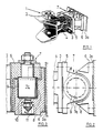
- FIG. 2 shows a top view of the trailer coupling 1 together with the load cell 7, while FIG. 3 shows a sectional view of FIG. 2.
- the support part 3 is supported via the coupling flange 5 and via a piston 7a on the connecting flange 6, which is designed as a housing 8 for the piston 7a.
- a piston 7a on the connecting flange 6 which is designed as a housing 8 for the piston 7a.
- elastomeric material 10 as indicated by dots.
- a pressure sensor 11 which is attached below the bottom of the housing 8, is connected.
- FIG. 4 shows a second embodiment of a trailer coupling 21.
- a trailer drawbar 22a of a trailer is inserted into the towing eye 22 and fixed by means of a plug pin 22b.
- the towing eye 22 merges into a bolt 24a, which can be rotated axially in a support ring 24 is stored.
- the support ring 24 is supported with its support part 23 to the rear against a frame part of the towing vehicle 23a.
- the bolt 24a as an inner element carries an axial bearing 24b at its front end in order to allow larger rotational movements of the bolt 24a.
- the tensile force is transmitted via a transmission ring 24c to a damping ring 24d, which is supported via the support ring 24 as an outer element.
- a further damping ring 34 is provided in the opposite direction in order to dampen changing, shock-like tensile and compressive loads on the trailer coupling 21.
- the trailer coupling shown here in Fig. 4 is state of the art and is used in many
- FIGS. 5 and 5a The embodiment of this trailer coupling retrofitted according to the invention is shown in FIGS. 5 and 5a, the latter showing the force measuring device designed according to the invention.
- the bolt 24a is in turn supported as an inner element via the axial bearing 24b, the transmission ring 24c and the damping ring 24d in the pulling direction.
- the damping ring 24d acts on an intermediate load cell 27, namely directly on its piston 27a, which acts on the pressure sensor 31 in the cylindrical annular space 30c, guided in the narrow annular gap 29a, 29b via the elastomeric material 30 (as indicated by dots).
- the pressure sensor 31 is here advantageously in the form of a type of spark plug and screwed into a shoulder of the housing 28, so that the pressure sensor 31 can be easily replaced.
- the housing 28 is fixed via a locking pin 32, acting in the same way as the stop 12 in FIG. 2.
- the force measuring cell 27 installed in the force path between the towing vehicle 23a and the trailer coupling 21 detects the tensile forces in the trailer coupling 21, while the compressive forces in the trailer coupling 21 are introduced via a damping ring 34, a housing 38, to a second force measuring cell 37 shown in the right-hand area.
- FIG. 5a shows the embodiment according to the invention, wherein the damping ring 24d is replaced with an otherwise identical structure by a plate spring assembly 24f which is supported between the rear 27b of the piston 27a and a radial surface of the transmission ring 24c.
- the piston 27a is loaded; without external load, the load cell 27 is biased in the pressure direction.
- the spring preload corresponds at least to the maximum compressive force.
- a fifth wheel coupling 51 according to DIN 74 081 is shown.
- the towing eye 52 is provided here in the center of a saddle plate 53, which is pivotally mounted on a lateral bearing block 54 on two lateral bearing blocks 54.
- FIGS. 6 and 7 shows a new embodiment of the trailer coupling in the form of the fifth wheel coupling according to FIGS. 6 and 7, it being possible for a force measuring arrangement to be formed using the force measuring device according to the invention.
- a replaceable bearing block 54 is provided on the fifth wheel coupling, which has a bearing for the transverse axis 55.
- the transverse axis 55 is provided in a first piston 67a, which is fitted in a housing 58 in the vertical direction and acts on a sensor 61 located below.
- two further horizontally aligned load cells 47 and 57 are provided, each with the same sensors 61, which detect the tensile forces and the compressive forces.
- the housing 58 of the first load cell 67 also forms the pistons 47a and 57a of the second and third load cells 47 and 57.
- all the forces necessary for the control of anti-lock braking systems are detected by a one-piece component 58 within the bearing block 64.
- the load cells 47 and 57 can also be separated from one another along the line, so that the vertical housing of the load cell is practically clamped and guided between the two horizontal load cells 47 and 57.
- two horizontal load cells 47 and 57 only a single one can be provided according to the embodiment in FIG. 5a, which is then biased by a spring at the level of the force to be expected.
- the triple load cell 67, 47, 57 shown in FIG. 8 can also be used in a trailer coupling 1 according to FIG. 1, the fastening parts of the bearing block 54 being replaced by the corresponding connecting parts, namely the coupling flange 5 and the connecting flange 6.
- the horizontal forces can also be measured by the load cells 47 and 57 in a bearing block 54, for example. while the load cell 67 for supporting force measurement is arranged in the second bearing block 54.
- the height of the gap 9 is chosen to be larger than the diameter of the piston 7a, preferably even larger than the diameter of the same.
- the invention is applicable to towbars, in particular on motor vehicle combinations and in railway wagons.
Applications Claiming Priority (3)
| Application Number | Priority Date | Filing Date | Title |
|---|---|---|---|
| DE3935479 | 1989-10-25 | ||
| DE3935479A DE3935479A1 (de) | 1989-10-25 | 1989-10-25 | Anhaengerkupplung |
| EP90120370A EP0428890B1 (fr) | 1989-10-25 | 1990-10-24 | Dispositif d'attelage de remorque avec boîte dynamométrique |
Related Parent Applications (1)
| Application Number | Title | Priority Date | Filing Date |
|---|---|---|---|
| EP90120370.3 Division | 1990-10-24 |
Publications (3)
| Publication Number | Publication Date |
|---|---|
| EP0437284A2 true EP0437284A2 (fr) | 1991-07-17 |
| EP0437284A3 EP0437284A3 (en) | 1992-04-08 |
| EP0437284B1 EP0437284B1 (fr) | 1994-05-25 |
Family
ID=6392147
Family Applications (2)
| Application Number | Title | Priority Date | Filing Date |
|---|---|---|---|
| EP90120370A Expired - Lifetime EP0428890B1 (fr) | 1989-10-25 | 1990-10-24 | Dispositif d'attelage de remorque avec boîte dynamométrique |
| EP91102543A Expired - Lifetime EP0437284B1 (fr) | 1989-10-25 | 1990-10-24 | Dispositif pour mesurer la force |
Family Applications Before (1)
| Application Number | Title | Priority Date | Filing Date |
|---|---|---|---|
| EP90120370A Expired - Lifetime EP0428890B1 (fr) | 1989-10-25 | 1990-10-24 | Dispositif d'attelage de remorque avec boîte dynamométrique |
Country Status (7)
| Country | Link |
|---|---|
| US (1) | US5060965A (fr) |
| EP (2) | EP0428890B1 (fr) |
| JP (1) | JPH03170825A (fr) |
| KR (1) | KR910007703A (fr) |
| AT (2) | ATE106140T1 (fr) |
| CA (1) | CA2028479A1 (fr) |
| DE (3) | DE3935479A1 (fr) |
Cited By (4)
| Publication number | Priority date | Publication date | Assignee | Title |
|---|---|---|---|---|
| EP0568068A2 (fr) * | 1992-04-30 | 1993-11-03 | Pfister Messtechnik GmbH | Dispositif de mesure de force |
| EP0607855A1 (fr) * | 1993-01-21 | 1994-07-27 | FELDBINDER & BECKMANN FAHRZEUGBAU oHG | Dispositif de mesure ou d'indication d'état de chargement d'une remorque |
| FR2701670A1 (fr) * | 1993-02-17 | 1994-08-26 | Fischer Georg Verkehrstechnik | Agencement de moyens de mesure sur l'accouplement à sellette d'un véhicule semi-remorque. |
| EP1106486A3 (fr) * | 1999-12-09 | 2003-03-12 | Holland Hitch Company | Couplage de traction de cinquième roue avec senseur de force |
Families Citing this family (34)
| Publication number | Priority date | Publication date | Assignee | Title |
|---|---|---|---|---|
| US5149121A (en) * | 1987-08-05 | 1992-09-22 | Pfister Gbmh | Force measuring device |
| DE9102783U1 (fr) * | 1991-03-08 | 1991-05-29 | Niederholz, Johannes, 4132 Kamp-Lintfort, De | |
| AU647996B1 (en) * | 1992-12-25 | 1994-03-31 | Kubota Corporation | Hydraulic control system for a tractor |
| GB9302762D0 (en) * | 1993-02-11 | 1993-03-24 | Lucas Ind Plc | Improvements in draw-bar couplings for articulated vehicles |
| DE4402528C2 (de) * | 1993-02-17 | 1996-07-04 | Fischer Georg Verkehrstechnik | Anordnung von Meßmitteln an einem Sattelfahrzeug |
| DE4402529A1 (de) * | 1993-02-17 | 1994-08-18 | Fischer Georg Verkehrstechnik | Anordnung von Meßmitteln an einem Sattelfahrzeug |
| DE4402525C2 (de) * | 1993-02-17 | 1998-10-29 | Fischer Georg Verkehrstechnik | Anordnung von Meßmitteln an einem eine Sattelzugmaschine und einen Sattelanhänger aufweisenden Sattelfahrzeug |
| DE4308774A1 (de) * | 1993-03-19 | 1994-06-09 | Daimler Benz Ag | Vorrichtung zur Messung der in eine Anhängevorrichtung eingeleiteten Stützkraft |
| DE9400547U1 (de) * | 1994-01-14 | 1994-03-17 | Nestler Guenther | Vorrichtung zum Verbinden von Anhängern u.dgl. |
| GB9407898D0 (en) * | 1994-04-21 | 1994-06-15 | Letchford Timothy G | Tow ball scales |
| DE4419673C2 (de) | 1994-06-07 | 1998-03-12 | Hottinger Messtechnik Baldwin | Anhängerkupplung mit einem Kraftaufnehmer |
| US6053521A (en) * | 1998-04-16 | 2000-04-25 | Schertler; Stephen James | Load sensing trailer ball-hitch drawbar |
| GB9907523D0 (en) * | 1999-04-01 | 1999-05-26 | Evans Kenneth S | Tow coupling sensor |
| JP2002220066A (ja) * | 2001-01-24 | 2002-08-06 | Yasunobu Akashio | フルトレーラの操舵装置 |
| DE10327564A1 (de) * | 2003-06-18 | 2005-01-05 | Robert Bosch Gmbh | Verfahren zur Bremsregelung eines Kraftfahrzeug-Anhängers |
| US6776299B1 (en) * | 2003-10-30 | 2004-08-17 | William Bernard Trescott | Automatic intermodal railway car coupler |
| DE102004031467B4 (de) * | 2004-06-30 | 2016-09-22 | Westfalia-Automotive Gmbh | Verfahren und Vorrichtung zum Betreiben eines Kraftfahrzeuges mit einer Anhängekupplung |
| EP1627803A1 (fr) * | 2004-08-19 | 2006-02-22 | Bradley Doublelock Limited | Remorques |
| DE102005030232A1 (de) * | 2005-06-29 | 2007-01-04 | Amazonen-Werke H. Dreyer Gmbh & Co. Kg | Vorrichtung für einen einachsigen Anhänger |
| DE102006007385A1 (de) * | 2006-02-17 | 2007-08-30 | Robert Bosch Gmbh | Kraftsensor und Herstellungsverfahren für einen Kraftsensor |
| DE102006030001A1 (de) * | 2006-06-29 | 2008-01-03 | Robert Bosch Gmbh | Regel- und Steuersystem in einem Fahrzeugverbund |
| US7584646B2 (en) | 2006-09-08 | 2009-09-08 | Ford Global Technologies, Llc | Device for measuring coefficient of friction |
| DE102006057326A1 (de) * | 2006-12-05 | 2008-06-19 | Magna Powertrain Ag & Co Kg | Kraftsensor |
| KR100941411B1 (ko) * | 2008-03-10 | 2010-02-10 | 현대로템 주식회사 | 비상 커플러용 어댑터 |
| DE102009034678B4 (de) | 2009-07-24 | 2019-04-25 | Volkswagen Ag | Verfahren zur Verbesserung einer Dynamikregelung für ein Fahrzeug mit einer Anhängerkupplung sowie Dynamikregelsystem und Fahrzeug |
| US8700270B2 (en) | 2011-07-11 | 2014-04-15 | Cnh America Llc | System and method for determining drawbar force magnitude and direction |
| DE102011117519A1 (de) * | 2011-11-03 | 2013-05-08 | Westfalia-Automotive Gmbh | Anhängekupplung mit einem Kraftsensor |
| CN107323190A (zh) * | 2017-07-05 | 2017-11-07 | 天津市博瑞特旅游观光火车有限公司 | 一种观光列车旋转牵引器 |
| US11428589B2 (en) | 2017-10-16 | 2022-08-30 | Saf-Holland, Inc. | Displacement sensor utilizing ronchi grating interference |
| US10960719B2 (en) | 2018-01-29 | 2021-03-30 | Progress Mfg. Inc. | Apparatus and method for measuring force on weight distribution hitches |
| DE102018106856A1 (de) * | 2018-03-22 | 2019-09-26 | Wabco Gmbh | Messeinrichtung zum Messen von Kräften und/oder Momenten zwischen einem motorisierten Fahrzeug und einem davon gezogenen oder geschobenen Anhänger oder Anbaugerät |
| DE102018106855A1 (de) * | 2018-03-22 | 2019-09-26 | Wabco Gmbh | Messeinrichtung zum Messen von Kräften und/oder Momenten zwischen einem motorisierten Fahrzeug und einem davon gezogenen oder geschobenen Anhänger oder Anbaugerät |
| US20190315169A1 (en) * | 2018-04-17 | 2019-10-17 | Ford Global Technologies, Llc | Indicator apparatus and related methods for use with vehicles |
| DE102021133761A1 (de) | 2021-12-17 | 2023-06-22 | Zf Cv Systems Global Gmbh | Verfahren zur Steuerung von Sicherheitsfunktionen eines Fahrzeuggespanns |
Citations (2)
| Publication number | Priority date | Publication date | Assignee | Title |
|---|---|---|---|---|
| EP0185296A1 (fr) * | 1984-12-10 | 1986-06-25 | Pfister GmbH | Procédé et appareil de fabrication de produit de type sandwich |
| EP0302437A2 (fr) * | 1987-08-05 | 1989-02-08 | Pfister GmbH | Dispositif de mesure de force |
Family Cites Families (11)
| Publication number | Priority date | Publication date | Assignee | Title |
|---|---|---|---|---|
| US1994388A (en) * | 1930-07-18 | 1935-03-12 | Erichsen Abraham Martinius | Apparatus for measuring and indicating forces |
| FR1438366A (fr) * | 1965-03-22 | 1966-05-13 | B A R A | Appareil de mesure de force ou pression |
| US3827709A (en) * | 1973-03-28 | 1974-08-06 | Amsted Ind Inc | Fifth wheel coupling |
| CH583110A5 (en) * | 1975-05-23 | 1976-12-31 | Beka St Aubin Sa | Trailer brake system actuated by coupling pressure - has pressure sensitive resistor for generating signals for actuating brake solenoids |
| US4279162A (en) * | 1979-11-23 | 1981-07-21 | Kelsey-Hayes Company | Pressure transducer |
| US4319766A (en) * | 1980-06-25 | 1982-03-16 | General Motors Corporation | Vehicle trailer hitch |
| DE3620360A1 (de) * | 1986-06-18 | 1987-12-23 | Pfister Gmbh | Elastostatische kraftmesseinrichtung |
| DE3530565C2 (de) * | 1985-08-27 | 2002-03-07 | Rockinger Spezial Fab Joh | Längskraftabstützung des Kupplungskörpers einer Anhängerkupplung |
| DE3530817C2 (de) * | 1985-08-29 | 1994-05-19 | Wabco Vermoegensverwaltung | Deichselkraftmeßeinrichtung |
| FI76293C (fi) * | 1987-05-21 | 1988-10-10 | Reijo Kankainen | Slaepvagnskoppling. |
| DE3842037A1 (de) * | 1988-12-14 | 1990-06-28 | Wabco Westinghouse Fahrzeug | Einrichtung zur erfassung einer axialkraft einer deichselkupplung |
-
1989
- 1989-10-25 DE DE3935479A patent/DE3935479A1/de not_active Withdrawn
-
1990
- 1990-10-24 AT AT91102543T patent/ATE106140T1/de not_active IP Right Cessation
- 1990-10-24 US US07/602,582 patent/US5060965A/en not_active Expired - Fee Related
- 1990-10-24 CA CA002028479A patent/CA2028479A1/fr not_active Abandoned
- 1990-10-24 AT AT90120370T patent/ATE117075T1/de active
- 1990-10-24 EP EP90120370A patent/EP0428890B1/fr not_active Expired - Lifetime
- 1990-10-24 EP EP91102543A patent/EP0437284B1/fr not_active Expired - Lifetime
- 1990-10-24 DE DE59008249T patent/DE59008249D1/de not_active Expired - Fee Related
- 1990-10-24 DE DE59005822T patent/DE59005822D1/de not_active Expired - Fee Related
- 1990-10-25 JP JP2286039A patent/JPH03170825A/ja active Pending
- 1990-10-25 KR KR1019900017167A patent/KR910007703A/ko not_active Application Discontinuation
Patent Citations (2)
| Publication number | Priority date | Publication date | Assignee | Title |
|---|---|---|---|---|
| EP0185296A1 (fr) * | 1984-12-10 | 1986-06-25 | Pfister GmbH | Procédé et appareil de fabrication de produit de type sandwich |
| EP0302437A2 (fr) * | 1987-08-05 | 1989-02-08 | Pfister GmbH | Dispositif de mesure de force |
Cited By (7)
| Publication number | Priority date | Publication date | Assignee | Title |
|---|---|---|---|---|
| EP0568068A2 (fr) * | 1992-04-30 | 1993-11-03 | Pfister Messtechnik GmbH | Dispositif de mesure de force |
| EP0568068A3 (fr) * | 1992-04-30 | 1993-11-24 | Pfister Messtechnik GmbH | Dispositif de mesure de force |
| EP0607855A1 (fr) * | 1993-01-21 | 1994-07-27 | FELDBINDER & BECKMANN FAHRZEUGBAU oHG | Dispositif de mesure ou d'indication d'état de chargement d'une remorque |
| WO1994016933A1 (fr) * | 1993-01-21 | 1994-08-04 | Feldbinder & Beckmann Fahrzeugbau Ohg | Dispositif de mesure et d'affichage de la charge d'une semi-remorque |
| FR2701670A1 (fr) * | 1993-02-17 | 1994-08-26 | Fischer Georg Verkehrstechnik | Agencement de moyens de mesure sur l'accouplement à sellette d'un véhicule semi-remorque. |
| EP1106486A3 (fr) * | 1999-12-09 | 2003-03-12 | Holland Hitch Company | Couplage de traction de cinquième roue avec senseur de force |
| US6739611B2 (en) | 1999-12-09 | 2004-05-25 | The Holland Group, Inc. | Force-sensing fifth wheel |
Also Published As
| Publication number | Publication date |
|---|---|
| EP0428890A3 (en) | 1992-03-18 |
| JPH03170825A (ja) | 1991-07-24 |
| EP0437284B1 (fr) | 1994-05-25 |
| CA2028479A1 (fr) | 1991-04-26 |
| EP0428890A2 (fr) | 1991-05-29 |
| DE3935479A1 (de) | 1991-05-02 |
| ATE117075T1 (de) | 1995-01-15 |
| KR910007703A (ko) | 1991-05-30 |
| US5060965A (en) | 1991-10-29 |
| DE59005822D1 (de) | 1994-06-30 |
| DE59008249D1 (de) | 1995-02-23 |
| ATE106140T1 (de) | 1994-06-15 |
| EP0428890B1 (fr) | 1995-01-11 |
| EP0437284A3 (en) | 1992-04-08 |
Similar Documents
| Publication | Publication Date | Title |
|---|---|---|
| EP0437284B1 (fr) | Dispositif pour mesurer la force | |
| WO2006092325A1 (fr) | Dispositif et procede pour l'ablation thermique de tissu biologique utilisant des schemas d’ablation spheriques | |
| DE4209835A1 (de) | Kugelverbindung | |
| EP0548487B1 (fr) | Dispositif pour mesurer une déformation d'une pièce de construction | |
| DE3111434A1 (de) | Vorrichtung zum messen der axialkraft in einer mittels rollenlagern gelagerten welle | |
| DE102011088461B4 (de) | Bauteilgruppe für ein Fahrzeug | |
| DE2351810A1 (de) | Dehnungs-messwertaufnehmer | |
| DE102010029414A1 (de) | Anhängekupplung | |
| DE19532883C2 (de) | Sicherheitslenksäule für ein Kraftfahrzeug | |
| DE4420489C2 (de) | Kugelgelenk | |
| EP0114046A2 (fr) | Paliers de sellette d'attelage de semi-remorque | |
| DE2739405C3 (de) | Hilfskraftlenkgetriebe | |
| DE102018200323B4 (de) | Blattfederanordnung für Kraftfahrzeuge | |
| DE19735753A1 (de) | Drehstabanordnung | |
| EP0000325B1 (fr) | Palier de fixation pour barre d'attelage | |
| DE102008039280A1 (de) | Achsschenkelbolzenlagerung und Verfahren zur Montage einer solchen | |
| EP1547900B1 (fr) | Agencement attachable pour roue | |
| DE2547959A1 (de) | Lastabhaengige schaltvorrichtung, insbesondere zum absichern beweglicher trittstufen an fahrzeugen zur personenbefoerderung | |
| EP0452622B1 (fr) | Dispositif de support en caoutchouc et métal pour barre flexible | |
| WO2017207801A1 (fr) | Ensemble ressort à lames et ressort à lames | |
| DE2815503C2 (de) | Zuggabellagerung für Anhänger von Kraftfahrzeugen | |
| DE7534036U (de) | Lastabhängige Schaltvorrichtung, insbesondere zum Absichern beweglicher Trittstufen an Fahrzeugen zur Personenbeförderung | |
| EP0433471B1 (fr) | Dispositif d'attelage avec support d'attelage ayant un disque de butée nervuré | |
| DE2311586A1 (de) | Aufhaengung stossartig beanspruchter fahrzeugteile, insbesondere federn oder zuggabeln von lkw-anhaengern | |
| DE2530996A1 (de) | Aufhaengung stossartig beanspruchter fahrzeugteile, insbesondere federn oder zuggabeln von lkw-anhaengern und mit dieser aufhaengung versehene zuggabel |
Legal Events
| Date | Code | Title | Description |
|---|---|---|---|
| PUAI | Public reference made under article 153(3) epc to a published international application that has entered the european phase |
Free format text: ORIGINAL CODE: 0009012 |
|
| AC | Divisional application: reference to earlier application |
Ref document number: 428890 Country of ref document: EP |
|
| AK | Designated contracting states |
Kind code of ref document: A2 Designated state(s): AT BE CH DE ES FR GB IT LI NL SE |
|
| RIN1 | Information on inventor provided before grant (corrected) |
Inventor name: HAEFNER, HANS WILHELM Inventor name: HEIMBACH, MANFRED |
|
| PUAL | Search report despatched |
Free format text: ORIGINAL CODE: 0009013 |
|
| AK | Designated contracting states |
Kind code of ref document: A3 Designated state(s): AT BE CH DE ES FR GB IT LI NL SE |
|
| 17P | Request for examination filed |
Effective date: 19920326 |
|
| 17Q | First examination report despatched |
Effective date: 19930902 |
|
| GRAA | (expected) grant |
Free format text: ORIGINAL CODE: 0009210 |
|
| AC | Divisional application: reference to earlier application |
Ref document number: 428890 Country of ref document: EP |
|
| AK | Designated contracting states |
Kind code of ref document: B1 Designated state(s): AT BE CH DE ES FR GB IT LI NL SE |
|
| PG25 | Lapsed in a contracting state [announced via postgrant information from national office to epo] |
Ref country code: IT Free format text: LAPSE BECAUSE OF FAILURE TO SUBMIT A TRANSLATION OF THE DESCRIPTION OR TO PAY THE FEE WITHIN THE PRE;WARNING: LAPSES OF ITALIAN PATENTS WITH EFFECTIVE DATE BEFORE 2007 MAY HAVE OCCURRED AT ANY TIME BEFORE 2007. THE CORRECT EFFECTIVE DATE MAY BE DIFFERENT FROM THE ONE RECORDED.SCRIBED TIME-LIMIT Effective date: 19940525 Ref country code: ES Free format text: THE PATENT HAS BEEN ANNULLED BY A DECISION OF A NATIONAL AUTHORITY Effective date: 19940525 Ref country code: BE Effective date: 19940525 Ref country code: SE Free format text: THE PATENT HAS BEEN ANNULLED BY A DECISION OF A NATIONAL AUTHORITY Effective date: 19940525 Ref country code: NL Effective date: 19940525 Ref country code: GB Effective date: 19940525 |
|
| REF | Corresponds to: |
Ref document number: 106140 Country of ref document: AT Date of ref document: 19940615 Kind code of ref document: T |
|
| REF | Corresponds to: |
Ref document number: 59005822 Country of ref document: DE Date of ref document: 19940630 |
|
| ET | Fr: translation filed | ||
| PG25 | Lapsed in a contracting state [announced via postgrant information from national office to epo] |
Ref country code: AT Effective date: 19941024 |
|
| PG25 | Lapsed in a contracting state [announced via postgrant information from national office to epo] |
Ref country code: LI Effective date: 19941031 Ref country code: CH Effective date: 19941031 |
|
| NLV1 | Nl: lapsed or annulled due to failure to fulfill the requirements of art. 29p and 29m of the patents act | ||
| GBV | Gb: ep patent (uk) treated as always having been void in accordance with gb section 77(7)/1977 [no translation filed] |
Effective date: 19940525 |
|
| PLBE | No opposition filed within time limit |
Free format text: ORIGINAL CODE: 0009261 |
|
| STAA | Information on the status of an ep patent application or granted ep patent |
Free format text: STATUS: NO OPPOSITION FILED WITHIN TIME LIMIT |
|
| 26N | No opposition filed | ||
| REG | Reference to a national code |
Ref country code: CH Ref legal event code: PL |
|
| PGFP | Annual fee paid to national office [announced via postgrant information from national office to epo] |
Ref country code: FR Payment date: 19960814 Year of fee payment: 7 |
|
| PG25 | Lapsed in a contracting state [announced via postgrant information from national office to epo] |
Ref country code: FR Free format text: THE PATENT HAS BEEN ANNULLED BY A DECISION OF A NATIONAL AUTHORITY Effective date: 19971031 |
|
| REG | Reference to a national code |
Ref country code: FR Ref legal event code: ST |
|
| PGFP | Annual fee paid to national office [announced via postgrant information from national office to epo] |
Ref country code: DE Payment date: 20031030 Year of fee payment: 14 |
|
| PG25 | Lapsed in a contracting state [announced via postgrant information from national office to epo] |
Ref country code: DE Free format text: LAPSE BECAUSE OF NON-PAYMENT OF DUE FEES Effective date: 20050503 |