EP0437029A1 - System zum Verschieben und Lagern von Trennwänden - Google Patents
System zum Verschieben und Lagern von Trennwänden Download PDFInfo
- Publication number
- EP0437029A1 EP0437029A1 EP90312240A EP90312240A EP0437029A1 EP 0437029 A1 EP0437029 A1 EP 0437029A1 EP 90312240 A EP90312240 A EP 90312240A EP 90312240 A EP90312240 A EP 90312240A EP 0437029 A1 EP0437029 A1 EP 0437029A1
- Authority
- EP
- European Patent Office
- Prior art keywords
- carriers
- track
- discs
- runs
- movement
- Prior art date
- Legal status (The legal status is an assumption and is not a legal conclusion. Google has not performed a legal analysis and makes no representation as to the accuracy of the status listed.)
- Granted
Links
- 239000000969 carrier Substances 0.000 claims abstract description 98
- 238000005192 partition Methods 0.000 description 14
- 238000010276 construction Methods 0.000 description 3
- 239000000725 suspension Substances 0.000 description 3
- 230000000903 blocking effect Effects 0.000 description 1
- 230000007935 neutral effect Effects 0.000 description 1
Images

Classifications
-
- E—FIXED CONSTRUCTIONS
- E05—LOCKS; KEYS; WINDOW OR DOOR FITTINGS; SAFES
- E05D—HINGES OR SUSPENSION DEVICES FOR DOORS, WINDOWS OR WINGS
- E05D15/00—Suspension arrangements for wings
- E05D15/06—Suspension arrangements for wings for wings sliding horizontally more or less in their own plane
- E05D15/0604—Suspension arrangements for wings for wings sliding horizontally more or less in their own plane allowing an additional movement
- E05D15/0608—Suspension arrangements for wings for wings sliding horizontally more or less in their own plane allowing an additional movement caused by track lay-out
- E05D15/0613—Suspension arrangements for wings for wings sliding horizontally more or less in their own plane allowing an additional movement caused by track lay-out with multi-directional trolleys
-
- E—FIXED CONSTRUCTIONS
- E06—DOORS, WINDOWS, SHUTTERS, OR ROLLER BLINDS IN GENERAL; LADDERS
- E06B—FIXED OR MOVABLE CLOSURES FOR OPENINGS IN BUILDINGS, VEHICLES, FENCES OR LIKE ENCLOSURES IN GENERAL, e.g. DOORS, WINDOWS, BLINDS, GATES
- E06B3/00—Window sashes, door leaves, or like elements for closing wall or like openings; Layout of fixed or moving closures, e.g. windows in wall or like openings; Features of rigidly-mounted outer frames relating to the mounting of wing frames
- E06B3/92—Doors or windows extensible when set in position
- E06B3/922—Doors or windows extensible when set in position with several wings opening horizontally towards the same side of the opening and each closing a separate part of the opening
- E06B3/924—Doors or windows extensible when set in position with several wings opening horizontally towards the same side of the opening and each closing a separate part of the opening positioned in one plane when closed
-
- E—FIXED CONSTRUCTIONS
- E05—LOCKS; KEYS; WINDOW OR DOOR FITTINGS; SAFES
- E05D—HINGES OR SUSPENSION DEVICES FOR DOORS, WINDOWS OR WINGS
- E05D15/00—Suspension arrangements for wings
- E05D15/06—Suspension arrangements for wings for wings sliding horizontally more or less in their own plane
- E05D15/0604—Suspension arrangements for wings for wings sliding horizontally more or less in their own plane allowing an additional movement
- E05D15/0608—Suspension arrangements for wings for wings sliding horizontally more or less in their own plane allowing an additional movement caused by track lay-out
-
- E—FIXED CONSTRUCTIONS
- E05—LOCKS; KEYS; WINDOW OR DOOR FITTINGS; SAFES
- E05Y—INDEXING SCHEME ASSOCIATED WITH SUBCLASSES E05D AND E05F, RELATING TO CONSTRUCTION ELEMENTS, ELECTRIC CONTROL, POWER SUPPLY, POWER SIGNAL OR TRANSMISSION, USER INTERFACES, MOUNTING OR COUPLING, DETAILS, ACCESSORIES, AUXILIARY OPERATIONS NOT OTHERWISE PROVIDED FOR, APPLICATION THEREOF
- E05Y2800/00—Details, accessories and auxiliary operations not otherwise provided for
-
- E—FIXED CONSTRUCTIONS
- E05—LOCKS; KEYS; WINDOW OR DOOR FITTINGS; SAFES
- E05Y—INDEXING SCHEME ASSOCIATED WITH SUBCLASSES E05D AND E05F, RELATING TO CONSTRUCTION ELEMENTS, ELECTRIC CONTROL, POWER SUPPLY, POWER SIGNAL OR TRANSMISSION, USER INTERFACES, MOUNTING OR COUPLING, DETAILS, ACCESSORIES, AUXILIARY OPERATIONS NOT OTHERWISE PROVIDED FOR, APPLICATION THEREOF
- E05Y2900/00—Application of doors, windows, wings or fittings thereof
- E05Y2900/10—Application of doors, windows, wings or fittings thereof for buildings or parts thereof
- E05Y2900/13—Type of wing
- E05Y2900/142—Partition walls
Definitions
- This invention relates to multi-directional suspension systems for operable walls or partitions and, more particularly, to a suspension track arrangement for automatically orienting such operable walls for storage and/or deployment.
- a partition suspension system which permits movement of subdividing walls or panels between a storage area and the point of intended use, the storage area being removed from the space to be subdivided.
- These systems for deployment and storage involve an overhead track grid arrangement, commonly made up of straight sections of track and lateral track sections which form, with the straight sections, right angle turns, cross-overs, and T-intersections, these being interspersed along the straight track sections.
- the subdivided areas may require a particular type of panel. For example, a fire-rated panel may be required when forming a corridor or a sound-rated panel may be required in designated areas.
- a fire-rated panel may be required when forming a corridor or a sound-rated panel may be required in designated areas.
- Another general object of this invention is to provide a track grid system which will automatically sort panels to insure that only a particular type of panel can be moved into a given operable position.
- a still further general object of this invention is to provide such attributes in a track grid system which is simple and cost effective.
- this invention contemplates a combination overhead grid track system and partition carriers. That is, the panels are supported from carriers which are positioned in and roll along the grid track system.
- the grid track system is made up of what will be termed main track runs and lateral track runs.
- the lateral track runs extend from the main tracks but open into the main tracks so that the carriers which are attached to operable wall can move selectively between the main and lateral track runs.
- the combination of obstructions in the main and lateral track runs with preselected carrier configurations insures the proper orientation of the panels for storage and/or the acceptance of only a preselected type of panel for operative positioning in a given track section.
- this is accomplished by providing the operable wall carrier with a projection which travels in the track runs with the carrier.
- An obstruction is positioned in the main track run and in the path of travel of the projection on the carrier.
- the obstruction is positioned in the area where the lateral track run opens into the main track run, and when the carrier projection engages the obstruction, the carrier is diverted into the adjacent, lateral track run.
- the lateral track run into which that carrier is diverted also includes an obstruction in the carrier path.
- the carrier diverted into the lateral run is further configured so that it clears the second obstruction and then can run freely into and through the lateral track run.
- the configuration which clears the obstruction in the lateral track run is provided on selective carriers which also include the diverter engaging projection. Others of the carriers are not so configured so that they will not clear the obstruction in the lateral track run and, thus, are prevented from entering the lateral track run.
- a ceiling grid track pattern or system is shown as being made up of track runs 10, 12 and 14.
- a number of portable partitions or walls 15 are suspended from the grid track system.
- the track system is viewed from below with walls 16 superimposed on the tracks and highlighted by shading, but illustrated in various positions which they can occupy.
- Slots 30 are illustrated and will be described more completely hereinafter. It will be appreciated slots 30 extend the length of the tracks, but have not been shown where the walls are superimposed.
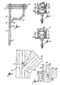
- Track runs 10, 12 and 14 have the same configuration with the exception of projections 16 and 18. Therefore, corresponding elements in Figs. 2 and 3 will be identified by the same numbers, track run 10 being illustrated in Fig. 2 and track run 12 being illustrated in Fig. 3.
- the tracks include an upper wall 20 and depending side walls 22 and 24.
- the lower ends of the side walls carry opposed ledges 26 and 28 which terminate in spaced relationship to define slot 30.
- the upper wall and side walls define an interior space and carriers 32 and 34 are positioned in that space.
- the carriers have different constructions and those differences will be explained hereinafter.
- carrier 32 includes a pendant bolt 36 which extends downwardly through slot 30.
- the lower end of bolt is threaded for attachment to the actual movable partition or wall (not shown in Fig. 2).
- a pair of discs 38 and 40 are journaled on the bolt 36 for rotation about the bolt.
- the underside of each disc has an angled surface 42 and 44 extending completely around the discs 38 and 40. Those angled surfaces 42 and 44 engage upwardly facing, preferably similarly angled surfaces 46 and 48.
- One angled surface 46 is part of ledge 26.
- Angled surface 48 is part of ledge 50 projecting from wall 24, but is spaced horizontally and vertically from ledge 26. With this arrangement, there is clearance for bolt 36 and discs 38 and 40 roll on ledges 26 and 50 in moving along the track.
- carrier 34 also includes a pendant bolt 52 extending through slot 30 for connection to an operable wall.
- Two discs 54 and 56 are journaled on bolt 52, with the undersides thereof having angled surfaces 58 and 60 engaged with the angle surfaces 46 and 48 in the track in the same manner and for the same reasons as set forth in connection with Fig. 2.
- Fig. 4 illustrates a portion of track run 10 in the area where track run 12 extends laterally from track run 10, but opens into track run 10 so that there is open communication for passage of the carriers between track runs 10 and 12.
- Track run 14 also opens into track run 10 for transfer of carriers therebetween.
- One of the objects of this invention is to provide a system which will automatically position the partitions for storage in a desired orientation. This is accomplished by preventing entry of the carriers into the lateral track runs for storage unless the partitions are properly oriented.
- bar 16 is attached to upper wall 20 of track run 10. As can be seen in Fig. 4, this bar is positioned in the area at which lateral track run 12 opens to the track run 10.
- the forward facing surface 62 is angled and positioned generally in alignment with slot 30 in track run 12.
- Carrier 32 extends upwardly but the head 64 of bolt 36 will ride under bar 16.
- bolt 52 includes an upper extension, projection 66, which extends above the uppermost disc 56 into the recess 68 provided in wall 20.
- Projection 66 is preferably in the form of a roller journaled on the end bolt 52. Bar 16 is in the path of movement of projection 66 in track run 10. When projection 66 engages surface 62 of bar 16, carrier 34 is diverted into track run 12.
- carrier 34 is shown in track run 12 after it has been diverted and carrier 32 is illustrated in track run 10 as it clears bar 16.
- disc 54 of the carrier has a dimensionally reduced portion in the axial direction or thickness of the disc, as compared to disc 56 and, more importantly, disc 38.
- disc 38 of carrier 32 which occupies the same relative position in carrier 32 as disc 54 in carrier 34, does not include a cut-out or relief portion 68.
- carrier 32 is at the entrance to lateral run 12, there will be interference between disc 38 and bar 18 which prevents carrier 32 from entering the lateral track run 12.
- carrier 32 is free to run in track run 10 until it reaches lateral track run 14.
- Lateral track run 14 is free of any projection such as 18 and carrier 32 can be moved into a storage position.
- a carrier 32 is positioned in the leading direction relative to partition movement along track run 10 toward a storage position.
- Carrier 34 is positioned in a trailing position.
- carrier 32 passes lateral track run 12 and reaches lateral track run 14 at the time carrier 34 reaches lateral track run 12.
- Carrier 34 is diverted into lateral track run 12 and the partitions are then stored in what is commonly referred to as parallel stacked relationship, i.e., parallel to each other and to track run 10.
- the partitions are stored in a preselected orientation as determined by the leading and trailing carriers.
- Fig. 5 illustrates what is commonly referred to as a side stack storage arrangement.
- track run 10' extends all the way to the storage area 17'.
- the carriers 32' and 34' are illustrated schematically by the shaded circles as they were in Fig. 1.
- Carrier 32' passes under bar 16' and bar 18' prevents entry of carrier 32' into the lateral track run in the manner already described.
- carrier 34' will be at the junction of track run 10' and lateral track run 12'.
- bar 18' will divert the carrier into track run 12'.
- the carrier 34' will continue in track run 12' to its storage position, the partition pivoting about carrier 32' to accommodate this movement.
- Figs. 6, 7 and 8 The embodiment of Figs. 6, 7 and 8 is to illustrate that the projection in the carriers which operates to divert the selected carriers into the lateral track runs can be a part of the disc itself.
- diverter bar 100 is fixed in track run 102, but at a lower level than was bar 16.
- bar 100 is attached to the lowermost portion 104 of shaped top wall 106.
- Carrier 108 is shown in track run 110 after it had been diverted by bar 100.
- Carrier 108 has an upper disc 112, the outer wall 114 of which extends upwardly in cylindrical fashion to provide an enlarged upper portion as compared to the carrier discs already described and to be described. This enlarged upper portion provides a projection which will engage bar 100 and will be diverted thereby to direct carrier 108 into lateral track 110.
- Disc 116 retains the cut-out portion 120 to clear bar 118 in lateral track 110.
- Carrier 122 is illustrated in track run 102.
- Upper disc 124 has a reduced axial dimension and head 126 of bolt 128 is recessed in disc 124 so that the disc and the bolt clear bar 100 allowing carrier 122 to continue along track run 102.
- Disc 130 has a full thickness in an axial direction, as did disc 38 so that it will engage bar 118, preventing carrier 122 from entering lateral track run 110.
- the preferred embodiment has been described in connection with movement into and out of storage.
- the same system of diverters in main track runs and blocking bars in lateral track runs can also be used in applications where the lateral track runs are operable runs for hanging particular walls in a described location.
- This system can be used to insure that only desired walls, for example, fire-rated or acoustical, can be moved into certain operative positions.
- Fig. 9 illustrates such an arrangement.
- carriers 32 and 34 have been shown schematically by shaded circles superimposed on main track runs and lateral track runs.
- the track runs form two cross-overs 130, 132 and a T-section 134 for illustrative purposes.
- Carriers 32 and 34 will have the configurations of Figs. 2 and 3 and deflector bar 16 and obstructing bars 18 are placed in various positions for illustrative purposes.
- the lateral track runs 136, 138, 140, 142, and 144 are at right angles to main track runs 146, 148, 150 and 152.
- Fig. 10 illustrates yet another embodiment.
- a pivotal arm 160 extends through the track wall and is supported on ledge 162 by pin 164.
- the arm is free to pivot about pin 164 between the full line position A and the dotted line positions B and C. In position A, it will engage the uppermost disc or bolt end and, by virtue of angled face 166, divert that carrier into track 168.
- the arm is moved by the carrier further into the track to position C and divert the carrier into track 168.
- Diverted carriers, or panels may have been moved into storage by means of other track sections. When these diverted channels are moving from storage along track section 170, the arm 160 will be engaged by the upper disc and is free to be moved to position B, by the disc or bolt, allowing the carrier to pass.
- Tension springs 172 and 174 are mounted between arm 160 and supports 176 and 178 and cooperate to bias arm 160 into position A, which is its neutral or normal position.
- the opening through which the arm extends into track 170 is bounded by edges 184 and 186.
- Edge 186 functions as a stop for arm 160 to establish position C at which the carrier is diverted.
- Track sections 168 and 170 are provided with bars 180 and 182 to prevent unwanted carriers from entering track sections 168 and 170, respectively.
- Panels may be provided only with carriers 32 or 34, or as in a storage application with one carrier 32 and one carrier 34.
Landscapes
- Engineering & Computer Science (AREA)
- Mechanical Engineering (AREA)
- Civil Engineering (AREA)
- Structural Engineering (AREA)
- Warehouses Or Storage Devices (AREA)
- Push-Button Switches (AREA)
- Motorcycle And Bicycle Frame (AREA)
- Support Devices For Sliding Doors (AREA)
- Sanitary Device For Flush Toilet (AREA)
- Electrical Discharge Machining, Electrochemical Machining, And Combined Machining (AREA)
- Devices For Checking Fares Or Tickets At Control Points (AREA)
- Fittings On The Vehicle Exterior For Carrying Loads, And Devices For Holding Or Mounting Articles (AREA)
- Automatic Disk Changers (AREA)
Applications Claiming Priority (2)
| Application Number | Priority Date | Filing Date | Title |
|---|---|---|---|
| US45415189A | 1989-12-21 | 1989-12-21 | |
| US454151 | 1999-12-03 |
Publications (2)
| Publication Number | Publication Date |
|---|---|
| EP0437029A1 true EP0437029A1 (de) | 1991-07-17 |
| EP0437029B1 EP0437029B1 (de) | 1996-04-24 |
Family
ID=23803514
Family Applications (1)
| Application Number | Title | Priority Date | Filing Date |
|---|---|---|---|
| EP90312240A Expired - Lifetime EP0437029B1 (de) | 1989-12-21 | 1990-11-08 | System zum Verschieben und Lagern von Trennwänden |
Country Status (9)
| Country | Link |
|---|---|
| EP (1) | EP0437029B1 (de) |
| JP (1) | JP2703119B2 (de) |
| AT (1) | ATE137300T1 (de) |
| AU (1) | AU636923B2 (de) |
| CA (1) | CA2029619C (de) |
| DE (1) | DE69026697T2 (de) |
| ES (1) | ES2086379T3 (de) |
| FI (1) | FI96713C (de) |
| MX (1) | MX174414B (de) |
Cited By (9)
| Publication number | Priority date | Publication date | Assignee | Title |
|---|---|---|---|---|
| FR2704577A1 (fr) * | 1993-04-27 | 1994-11-04 | Alga Flex | Cloison mobile. |
| US5448855A (en) * | 1991-03-27 | 1995-09-12 | Sjoeholm; Jarmo | Sliding element system |
| WO1997049885A1 (de) * | 1996-06-21 | 1997-12-31 | Dorma Gmbh & Co. Kg | Schiebewand |
| DE19734179A1 (de) * | 1997-08-07 | 1999-02-18 | Dorma Gmbh & Co Kg | An mindestens einer Laufschiene geführte Schiebewand |
| WO2000011298A1 (en) * | 1998-08-21 | 2000-03-02 | Iloxi Oy | Suspension assembly |
| DE19727928C2 (de) * | 1997-07-01 | 2001-11-29 | Dorma Gmbh & Co Kg | An mindestens einer Laufschiene geführte Schiebewand |
| WO2006089758A1 (en) * | 2005-02-25 | 2006-08-31 | Stichting Famecon | System for moving and positioning an element |
| JP2015090012A (ja) * | 2013-11-05 | 2015-05-11 | 株式会社岡村製作所 | 移動間仕切装置 |
| WO2021237252A1 (en) | 2020-05-22 | 2021-11-25 | Novelquip Forestry (Pty) Ltd | Planting apparatus |
Families Citing this family (2)
| Publication number | Priority date | Publication date | Assignee | Title |
|---|---|---|---|---|
| JP3910905B2 (ja) * | 2002-10-21 | 2007-04-25 | 有限会社インダストリーウォールシステム | 移動間仕切り装置 |
| JP6919878B2 (ja) * | 2016-10-28 | 2021-08-18 | 株式会社泉陽商会 | 移動間仕切壁構造 |
Citations (4)
| Publication number | Priority date | Publication date | Assignee | Title |
|---|---|---|---|---|
| FR1470504A (fr) * | 1966-03-02 | 1967-02-24 | Dispositif de support et de guidage de panneaux pour cloisons mobiles | |
| US3879799A (en) * | 1973-05-03 | 1975-04-29 | Hough Mfg Corp | Multidirectional suspension system for operable partitions |
| GB2102867A (en) * | 1980-12-08 | 1983-02-09 | Itoki Kosakusho | An apparatus for guiding movable suspended partition walls |
| US4569164A (en) * | 1983-04-08 | 1986-02-11 | Advanced Equipment Corp. | Operable wall system |
Family Cites Families (2)
| Publication number | Priority date | Publication date | Assignee | Title |
|---|---|---|---|---|
| US2657436A (en) * | 1951-08-14 | 1953-11-03 | John T Fairhurst | Sliding partition |
| AU170766A (en) * | 1966-02-16 | 1967-08-17 | L. Gogerty Henry | Means for guiding movable wall panels |
-
1990
- 1990-11-07 AU AU65850/90A patent/AU636923B2/en not_active Ceased
- 1990-11-08 ES ES90312240T patent/ES2086379T3/es not_active Expired - Lifetime
- 1990-11-08 AT AT90312240T patent/ATE137300T1/de not_active IP Right Cessation
- 1990-11-08 EP EP90312240A patent/EP0437029B1/de not_active Expired - Lifetime
- 1990-11-08 DE DE69026697T patent/DE69026697T2/de not_active Expired - Fee Related
- 1990-11-08 CA CA002029619A patent/CA2029619C/en not_active Expired - Fee Related
- 1990-12-05 MX MX023589A patent/MX174414B/es unknown
- 1990-12-17 JP JP2402913A patent/JP2703119B2/ja not_active Expired - Lifetime
- 1990-12-20 FI FI906332A patent/FI96713C/fi not_active IP Right Cessation
Patent Citations (4)
| Publication number | Priority date | Publication date | Assignee | Title |
|---|---|---|---|---|
| FR1470504A (fr) * | 1966-03-02 | 1967-02-24 | Dispositif de support et de guidage de panneaux pour cloisons mobiles | |
| US3879799A (en) * | 1973-05-03 | 1975-04-29 | Hough Mfg Corp | Multidirectional suspension system for operable partitions |
| GB2102867A (en) * | 1980-12-08 | 1983-02-09 | Itoki Kosakusho | An apparatus for guiding movable suspended partition walls |
| US4569164A (en) * | 1983-04-08 | 1986-02-11 | Advanced Equipment Corp. | Operable wall system |
Cited By (15)
| Publication number | Priority date | Publication date | Assignee | Title |
|---|---|---|---|---|
| US5448855A (en) * | 1991-03-27 | 1995-09-12 | Sjoeholm; Jarmo | Sliding element system |
| FR2704577A1 (fr) * | 1993-04-27 | 1994-11-04 | Alga Flex | Cloison mobile. |
| AU733648B2 (en) * | 1996-06-21 | 2001-05-17 | Dorma Gmbh & Co. Kg | Sliding wall |
| WO1997049885A1 (de) * | 1996-06-21 | 1997-12-31 | Dorma Gmbh & Co. Kg | Schiebewand |
| US6286258B1 (en) | 1996-06-21 | 2001-09-11 | Dorma Gmbh + Co. Kg | Movable wall |
| DE19727928C2 (de) * | 1997-07-01 | 2001-11-29 | Dorma Gmbh & Co Kg | An mindestens einer Laufschiene geführte Schiebewand |
| DE19734179A1 (de) * | 1997-08-07 | 1999-02-18 | Dorma Gmbh & Co Kg | An mindestens einer Laufschiene geführte Schiebewand |
| US6286277B1 (en) | 1997-08-07 | 2001-09-11 | Dorma Gmbh + Co. Kg | Sliding panel system having panels sliding along at least one slide rail arrangement |
| DE19734179C2 (de) * | 1997-08-07 | 1999-09-02 | Dorma Gmbh & Co Kg | An mindestens einer Laufschiene geführte Schiebewand |
| WO1999007970A1 (de) | 1997-08-07 | 1999-02-18 | Dorma Gmbh + Co. Kg | An mindestens einer laufschiene geführte schiebewand |
| WO2000011298A1 (en) * | 1998-08-21 | 2000-03-02 | Iloxi Oy | Suspension assembly |
| WO2006089758A1 (en) * | 2005-02-25 | 2006-08-31 | Stichting Famecon | System for moving and positioning an element |
| JP2015090012A (ja) * | 2013-11-05 | 2015-05-11 | 株式会社岡村製作所 | 移動間仕切装置 |
| WO2021237252A1 (en) | 2020-05-22 | 2021-11-25 | Novelquip Forestry (Pty) Ltd | Planting apparatus |
| US11818978B2 (en) | 2020-05-22 | 2023-11-21 | Novelquip Forestry (Pty) Ltd | Planting apparatus |
Also Published As
| Publication number | Publication date |
|---|---|
| FI96713B (fi) | 1996-04-30 |
| FI906332A (fi) | 1991-06-22 |
| JPH03290577A (ja) | 1991-12-20 |
| ATE137300T1 (de) | 1996-05-15 |
| JP2703119B2 (ja) | 1998-01-26 |
| FI906332A0 (fi) | 1990-12-20 |
| DE69026697D1 (de) | 1996-05-30 |
| FI96713C (fi) | 1996-08-12 |
| EP0437029B1 (de) | 1996-04-24 |
| AU636923B2 (en) | 1993-05-13 |
| CA2029619C (en) | 2000-01-11 |
| DE69026697T2 (de) | 1996-11-28 |
| CA2029619A1 (en) | 1991-06-22 |
| AU6585090A (en) | 1991-06-27 |
| ES2086379T3 (es) | 1996-07-01 |
| MX174414B (es) | 1994-05-13 |
Similar Documents
| Publication | Publication Date | Title |
|---|---|---|
| US5230123A (en) | Operable wall deployment and storage system | |
| EP0437029B1 (de) | System zum Verschieben und Lagern von Trennwänden | |
| US4386645A (en) | Side folding closure | |
| US3879799A (en) | Multidirectional suspension system for operable partitions | |
| US5016318A (en) | Multi-directional radial wheel trolley and track for operable walls | |
| US7255045B2 (en) | Multi-program trolleys and switches | |
| US5063636A (en) | Track system for operable wall | |
| US3356402A (en) | Framing system for a suspended ceiling | |
| US4583340A (en) | Fixture support clip for suspension ceiling grid systems | |
| US4733925A (en) | Device for the suspended arrangement of juxtaposed individual tilting compartments | |
| US2657436A (en) | Sliding partition | |
| AU733294B2 (en) | Arrangement for pivotable and slidable suspension of sheets | |
| US4064671A (en) | Stabilizer strut for suspended ceiling system | |
| US4625470A (en) | Openwork screen assembly | |
| CA2121651C (en) | Track and rail-form slider combination | |
| US3544787A (en) | Louver construction | |
| AU771625B2 (en) | Automatic track switching system for operable walls | |
| US6855063B2 (en) | Arbor guide shoe assembly for counterweight system | |
| US4509652A (en) | Baker's rack | |
| US6848214B2 (en) | Movable wall system having a plurality of movable panels, a runner rail, and a tracking-switching arrangement | |
| EP0851962A1 (de) | Verfahren und vorrichtung zum anbringen von glas in einen offenen raum | |
| WO2003042478A1 (en) | Arrangement for providing a swivel point | |
| JP2539060B2 (ja) | 格納庫用大型引き戸の開閉装置 | |
| JPH0443549B2 (de) | ||
| CA2028654A1 (en) | Partition track system |
Legal Events
| Date | Code | Title | Description |
|---|---|---|---|
| PUAI | Public reference made under article 153(3) epc to a published international application that has entered the european phase |
Free format text: ORIGINAL CODE: 0009012 |
|
| AK | Designated contracting states |
Kind code of ref document: A1 Designated state(s): AT BE CH DE DK ES FR GB GR IT LI LU NL SE |
|
| 17P | Request for examination filed |
Effective date: 19911227 |
|
| 17Q | First examination report despatched |
Effective date: 19920130 |
|
| GRAA | (expected) grant |
Free format text: ORIGINAL CODE: 0009210 |
|
| AK | Designated contracting states |
Kind code of ref document: B1 Designated state(s): AT BE CH DE DK ES FR GB GR IT LI LU NL SE |
|
| PG25 | Lapsed in a contracting state [announced via postgrant information from national office to epo] |
Ref country code: LI Effective date: 19960424 Ref country code: GR Free format text: LAPSE BECAUSE OF FAILURE TO SUBMIT A TRANSLATION OF THE DESCRIPTION OR TO PAY THE FEE WITHIN THE PRESCRIBED TIME-LIMIT Effective date: 19960424 Ref country code: DK Effective date: 19960424 Ref country code: CH Effective date: 19960424 Ref country code: AT Effective date: 19960424 |
|
| REF | Corresponds to: |
Ref document number: 137300 Country of ref document: AT Date of ref document: 19960515 Kind code of ref document: T |
|
| REF | Corresponds to: |
Ref document number: 69026697 Country of ref document: DE Date of ref document: 19960530 |
|
| REG | Reference to a national code |
Ref country code: ES Ref legal event code: FG2A Ref document number: 2086379 Country of ref document: ES Kind code of ref document: T3 |
|
| ITF | It: translation for a ep patent filed |
Owner name: UFFICIO TECNICO ING. A. MANNUCCI |
|
| PG25 | Lapsed in a contracting state [announced via postgrant information from national office to epo] |
Ref country code: SE Effective date: 19960724 |
|
| ET | Fr: translation filed | ||
| REG | Reference to a national code |
Ref country code: CH Ref legal event code: PL |
|
| PG25 | Lapsed in a contracting state [announced via postgrant information from national office to epo] |
Ref country code: LU Free format text: LAPSE BECAUSE OF NON-PAYMENT OF DUE FEES Effective date: 19961130 |
|
| PLBE | No opposition filed within time limit |
Free format text: ORIGINAL CODE: 0009261 |
|
| STAA | Information on the status of an ep patent application or granted ep patent |
Free format text: STATUS: NO OPPOSITION FILED WITHIN TIME LIMIT |
|
| 26N | No opposition filed | ||
| PGFP | Annual fee paid to national office [announced via postgrant information from national office to epo] |
Ref country code: GB Payment date: 20001108 Year of fee payment: 11 |
|
| PGFP | Annual fee paid to national office [announced via postgrant information from national office to epo] |
Ref country code: FR Payment date: 20001110 Year of fee payment: 11 |
|
| PGFP | Annual fee paid to national office [announced via postgrant information from national office to epo] |
Ref country code: ES Payment date: 20001128 Year of fee payment: 11 |
|
| PGFP | Annual fee paid to national office [announced via postgrant information from national office to epo] |
Ref country code: NL Payment date: 20001130 Year of fee payment: 11 |
|
| PGFP | Annual fee paid to national office [announced via postgrant information from national office to epo] |
Ref country code: BE Payment date: 20010123 Year of fee payment: 11 |
|
| PG25 | Lapsed in a contracting state [announced via postgrant information from national office to epo] |
Ref country code: GB Free format text: LAPSE BECAUSE OF NON-PAYMENT OF DUE FEES Effective date: 20011108 |
|
| PG25 | Lapsed in a contracting state [announced via postgrant information from national office to epo] |
Ref country code: ES Free format text: LAPSE BECAUSE OF NON-PAYMENT OF DUE FEES Effective date: 20011109 |
|
| PGFP | Annual fee paid to national office [announced via postgrant information from national office to epo] |
Ref country code: DE Payment date: 20011126 Year of fee payment: 12 |
|
| PG25 | Lapsed in a contracting state [announced via postgrant information from national office to epo] |
Ref country code: BE Free format text: LAPSE BECAUSE OF NON-PAYMENT OF DUE FEES Effective date: 20011130 |
|
| REG | Reference to a national code |
Ref country code: GB Ref legal event code: IF02 |
|
| BERE | Be: lapsed |
Owner name: HUFCOR INC. Effective date: 20011130 |
|
| PG25 | Lapsed in a contracting state [announced via postgrant information from national office to epo] |
Ref country code: NL Free format text: LAPSE BECAUSE OF NON-PAYMENT OF DUE FEES Effective date: 20020601 |
|
| GBPC | Gb: european patent ceased through non-payment of renewal fee |
Effective date: 20011108 |
|
| PG25 | Lapsed in a contracting state [announced via postgrant information from national office to epo] |
Ref country code: FR Free format text: LAPSE BECAUSE OF NON-PAYMENT OF DUE FEES Effective date: 20020730 |
|
| NLV4 | Nl: lapsed or anulled due to non-payment of the annual fee |
Effective date: 20020601 |
|
| REG | Reference to a national code |
Ref country code: FR Ref legal event code: ST |
|
| REG | Reference to a national code |
Ref country code: FR Ref legal event code: ST |
|
| PG25 | Lapsed in a contracting state [announced via postgrant information from national office to epo] |
Ref country code: DE Free format text: LAPSE BECAUSE OF NON-PAYMENT OF DUE FEES Effective date: 20030603 |
|
| REG | Reference to a national code |
Ref country code: ES Ref legal event code: FD2A Effective date: 20021213 |
|
| PG25 | Lapsed in a contracting state [announced via postgrant information from national office to epo] |
Ref country code: IT Free format text: LAPSE BECAUSE OF NON-PAYMENT OF DUE FEES;WARNING: LAPSES OF ITALIAN PATENTS WITH EFFECTIVE DATE BEFORE 2007 MAY HAVE OCCURRED AT ANY TIME BEFORE 2007. THE CORRECT EFFECTIVE DATE MAY BE DIFFERENT FROM THE ONE RECORDED. Effective date: 20051108 |