EP0435757B1 - Verfahren und Vorrichtung zur gleichzeitigen Messung des Abstandes zwischen metallischen Tuben und der Oxyde-Dicke auf den Tuben - Google Patents
Verfahren und Vorrichtung zur gleichzeitigen Messung des Abstandes zwischen metallischen Tuben und der Oxyde-Dicke auf den Tuben Download PDFInfo
- Publication number
- EP0435757B1 EP0435757B1 EP90403710A EP90403710A EP0435757B1 EP 0435757 B1 EP0435757 B1 EP 0435757B1 EP 90403710 A EP90403710 A EP 90403710A EP 90403710 A EP90403710 A EP 90403710A EP 0435757 B1 EP0435757 B1 EP 0435757B1
- Authority
- EP
- European Patent Office
- Prior art keywords
- probe
- tubes
- measurement
- oxide
- thickness
- Prior art date
- Legal status (The legal status is an assumption and is not a legal conclusion. Google has not performed a legal analysis and makes no representation as to the accuracy of the status listed.)
- Expired - Lifetime
Links
- 238000000034 method Methods 0.000 title claims description 12
- 239000000523 sample Substances 0.000 claims description 65
- 238000005259 measurement Methods 0.000 claims description 46
- 238000006073 displacement reaction Methods 0.000 claims description 12
- 229910052751 metal Inorganic materials 0.000 claims description 10
- 239000002184 metal Substances 0.000 claims description 10
- 238000012545 processing Methods 0.000 claims description 4
- 239000000446 fuel Substances 0.000 description 10
- 230000006870 function Effects 0.000 description 7
- 230000000712 assembly Effects 0.000 description 6
- 238000000429 assembly Methods 0.000 description 6
- 238000010586 diagram Methods 0.000 description 6
- 229910045601 alloy Inorganic materials 0.000 description 4
- 239000000956 alloy Substances 0.000 description 4
- 239000003758 nuclear fuel Substances 0.000 description 4
- 239000003507 refrigerant Substances 0.000 description 4
- QCWXUUIWCKQGHC-UHFFFAOYSA-N Zirconium Chemical compound [Zr] QCWXUUIWCKQGHC-UHFFFAOYSA-N 0.000 description 3
- 238000004364 calculation method Methods 0.000 description 3
- 238000011088 calibration curve Methods 0.000 description 3
- 239000011810 insulating material Substances 0.000 description 3
- 229910052726 zirconium Inorganic materials 0.000 description 3
- MCMNRKCIXSYSNV-UHFFFAOYSA-N Zirconium dioxide Chemical compound O=[Zr]=O MCMNRKCIXSYSNV-UHFFFAOYSA-N 0.000 description 2
- 238000005253 cladding Methods 0.000 description 2
- 230000007423 decrease Effects 0.000 description 2
- 239000000463 material Substances 0.000 description 2
- 230000002093 peripheral effect Effects 0.000 description 2
- BASFCYQUMIYNBI-UHFFFAOYSA-N platinum Chemical compound [Pt] BASFCYQUMIYNBI-UHFFFAOYSA-N 0.000 description 2
- 238000013139 quantization Methods 0.000 description 2
- 230000001360 synchronised effect Effects 0.000 description 2
- XLYOFNOQVPJJNP-UHFFFAOYSA-N water Substances O XLYOFNOQVPJJNP-UHFFFAOYSA-N 0.000 description 2
- 240000005561 Musa balbisiana Species 0.000 description 1
- 235000018290 Musa x paradisiaca Nutrition 0.000 description 1
- 230000015572 biosynthetic process Effects 0.000 description 1
- 239000004020 conductor Substances 0.000 description 1
- 238000005336 cracking Methods 0.000 description 1
- 238000009795 derivation Methods 0.000 description 1
- 230000001627 detrimental effect Effects 0.000 description 1
- 239000000284 extract Substances 0.000 description 1
- 238000001914 filtration Methods 0.000 description 1
- 230000004992 fission Effects 0.000 description 1
- 229910001026 inconel Inorganic materials 0.000 description 1
- 229910000816 inconels 718 Inorganic materials 0.000 description 1
- 230000000977 initiatory effect Effects 0.000 description 1
- 239000000696 magnetic material Substances 0.000 description 1
- 238000000691 measurement method Methods 0.000 description 1
- 239000007769 metal material Substances 0.000 description 1
- 230000035515 penetration Effects 0.000 description 1
- 238000012552 review Methods 0.000 description 1
- 238000005070 sampling Methods 0.000 description 1
- 238000012883 sequential measurement Methods 0.000 description 1
- 239000007787 solid Substances 0.000 description 1
- 229920003002 synthetic resin Polymers 0.000 description 1
- 239000000057 synthetic resin Substances 0.000 description 1
- 238000012795 verification Methods 0.000 description 1
Images

Classifications
-
- G—PHYSICS
- G01—MEASURING; TESTING
- G01B—MEASURING LENGTH, THICKNESS OR SIMILAR LINEAR DIMENSIONS; MEASURING ANGLES; MEASURING AREAS; MEASURING IRREGULARITIES OF SURFACES OR CONTOURS
- G01B7/00—Measuring arrangements characterised by the use of electric or magnetic techniques
- G01B7/02—Measuring arrangements characterised by the use of electric or magnetic techniques for measuring length, width or thickness
- G01B7/06—Measuring arrangements characterised by the use of electric or magnetic techniques for measuring length, width or thickness for measuring thickness
- G01B7/10—Measuring arrangements characterised by the use of electric or magnetic techniques for measuring length, width or thickness for measuring thickness using magnetic means, e.g. by measuring change of reluctance
- G01B7/105—Measuring arrangements characterised by the use of electric or magnetic techniques for measuring length, width or thickness for measuring thickness using magnetic means, e.g. by measuring change of reluctance for measuring thickness of coating
-
- G—PHYSICS
- G01—MEASURING; TESTING
- G01B—MEASURING LENGTH, THICKNESS OR SIMILAR LINEAR DIMENSIONS; MEASURING ANGLES; MEASURING AREAS; MEASURING IRREGULARITIES OF SURFACES OR CONTOURS
- G01B7/00—Measuring arrangements characterised by the use of electric or magnetic techniques
- G01B7/02—Measuring arrangements characterised by the use of electric or magnetic techniques for measuring length, width or thickness
- G01B7/06—Measuring arrangements characterised by the use of electric or magnetic techniques for measuring length, width or thickness for measuring thickness
- G01B7/10—Measuring arrangements characterised by the use of electric or magnetic techniques for measuring length, width or thickness for measuring thickness using magnetic means, e.g. by measuring change of reluctance
-
- G—PHYSICS
- G01—MEASURING; TESTING
- G01B—MEASURING LENGTH, THICKNESS OR SIMILAR LINEAR DIMENSIONS; MEASURING ANGLES; MEASURING AREAS; MEASURING IRREGULARITIES OF SURFACES OR CONTOURS
- G01B7/00—Measuring arrangements characterised by the use of electric or magnetic techniques
- G01B7/14—Measuring arrangements characterised by the use of electric or magnetic techniques for measuring distance or clearance between spaced objects or spaced apertures
Definitions
- the present invention relates to the measurement of the distance between substantially parallel metal tubes constituting a sheet and of the thickness of oxide possibly covering the tubes. It finds a particularly important, although not exclusive, application in the measurement of the distance between the metal tubes constituting the sheaths of rods belonging to nuclear fuel assemblies and the thickness of oxide covering these tubes.
- the reduction in spacing can in particular be caused by an arcuate or banana deformation of certain pencils, locally reducing the spacing between surfaces facing the sheaths.
- the reduction can generate hot spots and lead to the piercing of the sheaths, especially when they come into contact. Even if the consequences are not as serious, the variations in spacing create refrigerant circulation faults and disturb the thermodynamic cycle in a manner detrimental to the proper functioning of the reactor.
- the probe consists of a corner carrying a coil, which is inserted more or less deeply between the tubes, according to their spacing (US-A-3,225,294).
- the thickness of the oxide layer formed on the surface of the sheath in contact with the refrigerant is also desirable to measure the thickness of the oxide layer formed on the surface of the sheath in contact with the refrigerant.
- This oxide layer decreases the heat exchange coefficient between the sheath and the refrigerant and consequently causes the sheath to overheat.
- the claddings made of zirconium-based alloy are progressively covered with a layer of zirconia.
- the thickness of this layer exceeds a limit, of approximately 100 ⁇ m in current pressurized water reactors, the phenomenon of oxide formation tends to get carried away and can lead to cracking of the cladding and therefore to the passage fission products in the refrigerant.
- the spacing between rods of an assembly is generally appreciated by scrolling a camera opposite the gap between rods, along the assembly.
- the camera is equipped with a reference reticle and an operator follows the variations in spacing between the pens on the display screen. This measurement method is painful and its reliability is uncertain.
- the present invention aims to provide a method and a device for simultaneously measuring the distance between substantially parallel metal tubes constituting a sheet, in particular between tubes constituting the sheaths of the rods of a fuel assembly, and the thickness of oxide covering the tubes.
- An accessory object of the invention is to provide a method and a measuring device making it possible to reduce the examination time of an assembly in considerable proportions, in comparison with the prior art.
- it aims to provide a device which can be produced in a form making it possible to measure the spacing and the thicknesses inside an assembly.
- the invention proposes in particular a method of simultaneous measurement of the distance between substantially parallel metal tubes constituting a sheet and of the thickness of oxide covering the tubes, according to claim 1.
- the invention also provides a device making it possible to implement the above-defined method according to claim 3.
- the measuring apparatus comprises a table with crossed displacements carrying a plate on which the probe is mounted by means making it possible to push it elastically in one of the directions of movement of the table, said plate being moreover movable on the table by means making it possible to circulate the probe on several parallel tubes having predetermined oxide thicknesses and known and allowing it to be brought into a measurement position where it is parallel to said direction of movement.
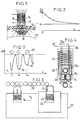
- FIG. 1 shows a fraction of a sheath 10, made of a zirconium-based alloy in general, on which a non-conductive oxide layer 12 has formed.
- An eddy current probe 13 comprises a core of magnetic material 14 carrying a coil 16 to which an electrical voltage at high frequency is applied, generally between 1 and 4 MHz.
- the probe 14 When the probe 14 is in contact with the sheath 10, it induces eddy currents, shown diagrammatically by lines 18, in the conductive part, that is to say in the metal of the sheath.
- the impedance Z of the coil 16 has the appearance shown in FIG. 2: for a zero oxide thickness, the impedance Z of the coil has a maximum value Z O. As the thickness e increases, the apparent impedance decreases and tends asymptotically towards a value Z1. The measurement of the impedance Z in the zone where it varies rapidly with the thickness makes it possible to determine the thickness of the oxide.
- the working frequency will be chosen so as to allow a significant measurement at least up to the maximum tolerable thickness, that is to say approximately 100 ⁇ m in the case of a sheath.
- a frequency of 1.5 MHz will often be satisfactory in the case of zirconium-based alloy sheaths.
- a device for the sequential measurement of the oxide thicknesses on rods 20 of a peripheral fuel assembly sheet without having to raise the probe, to move transversely, then to reapply it at each operation, a device according to the invention comprises a housing 22 in which an eddy current probe 13 is mounted so as to be able to slide parallel to the axis of its coil 16 and elastic means, shown diagrammatically by a spring 24, which tend to bring the probe 13 in the maximum projection position where it is shown in solid lines in FIG. 3.
- the housing 22 is carried by a table with crossed movements 26, making it possible to move it in a direction y parallel to the axis of the probe 13 and an orthogonal direction x .
- the core of the probe 13 (or a head in which this probe is embedded) has a projecting end portion of frustoconical shape, the conicity of which is such that, when the housing 22 is moved in the x direction from the initial position where it is shown in FIG. 3, the probe constitutes a feeler which remains, under the pressure of the spring 24, in permanent contact with the sheaths of the rods 20, and follows their contours.
- the probe 13 comprises a core 14 fixed in the axis of a head 28 made of insulating material, having a frustoconical end portion.
- the core is flush with the end of the head 28.
- It carries the measuring coil 16 which creates a field whose lines of force pass through the sheath of the pencil 20 to be checked.
- It also carries, behind the coil 16, a reference coil 16a which creates a field whose lines of force cross a section of sheath 20a embedded in the head 28, in contact with the core 14 and in alignment with this core.
- This section of sheath represents a reference standard, which is chosen not oxidized.
- the coils 16 and 16a are connected to external circuits, which will be described later, by conductors 30 and 30a.
- a measurement sequence carried out on the rods 20 of a sheet involves bringing the box 22, by displacements in x and y of the table 26 controlled manually, in the position shown in FIG. 3, then actuating the table 26 to move the box in the direction x .
- the head 28 then follows the profile of the pencils 20.
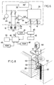
- the external circuits for processing the signal supplied by the probe can have the basic principle shown in FIG. 6. These circuits include an analog part and a digital part.
- the analog part has a generator 32 providing a sinusoidal voltage common reference, for example at 1.5 MHz.
- a differential voltage ⁇ V appears between the coils.
- a differential amplifier 34 amplifies this voltage and applies it to a synchronous detector 36 which also receives, as reference signals, the output voltage of the generator 32 and the same voltage phase shifted by 90 ° by a phase shifter 38.
- the synchronous detector extracts the components X and Y of the vector ⁇ V which are subjected to bandpass filtering in noise reduction filters 38.
- the output signal ⁇ V and the component X exhibit variations as a function of the distance x of the kind shown in FIG. 7.
- the signal X has successive maxima corresponding when the probe passes in the middle of the interval between two successive pencils. These maxima have practically all the same value, given the absence of metallic material in line with the probe at these locations.
- the signal also passes through successive minima V1, V2, V3 when the probe 13 is in line with the generatrices of each of the successive pencils, for positrons x1, x2, x3 of the probe.
- the amplitude of the minima is a direct function of the thickness of oxide present on the sheath.
- this digital part comprises a sampler 40 whose sampling rate is advantageously fixed by a sensor 42 for measuring the displacement in x of the table 26, constituted for example by a digital encoder.
- the increment step of the sensor is chosen according to the resolution desired for the measurement.
- the measurement results can be stored in mass memory 50 (hard disks, floppy disks, etc.) and viewed in real time or in deferred time.
- the measurements can be very precise. Because the measurements are made on the fly, by a simple linear displacement of the table 46, they can be much faster than in the methods according to the prior art.
- the calibration curve of FIG. 2 can be established prior to the measurement of the oxide thicknesses on the rods of a sheet and stored, for the entire duration of the control of an assembly, in cartographic form in RAM 48.
- a more advantageous solution consists in periodically carrying out a verification and possibly an updating of the calibration curve of FIG. 2 between successive measurement sequences. For this, it is possible to use a mounting of the head on the table 26 of the kind shown in FIGS. 5A and 5B.
- a plate 54 On the plate 52, movable along x and y , of the cross-motion table 26 is mounted a plate 54.
- the plate can rotate on the plate 52 around an axis 56 parallel to the axis of the pencils 20 to be checked (axis z ).
- Displacement means shown diagrammatically by a jack 58 interposed between the plate 54 and the plate 52, make it possible to rotate the plate 54 between a measurement position where it is represented in FIG. 5B and calibration positions.
- the plate carries the housing 22 containing a head 28 which can be of the type shown in FIG. 4.
- the axis of the housing 22 and of the probe 13 is directed orthogonally to the sheet of rods 20: when the table 26 is actuated to move the housing 22 in the x direction, the operation is that which has just been described.
- the cross-motion table 26 is controlled so as to release the housing 22 from the pencil ply 20. Then the jack 58 is actuated to move the housing 22 in the direction indicated by the arrow f on the Figure 5A, from the measurement position.
- the plate 52 carries pluselles calibration tubes 60 whose axes are parallel to those of the rods 20 and which are covered with staggered oxide thicknesses, generally from a thin thickness to the maximum thickness to be measured. These tubes 60 can be constituted by sheath sections identical to those of the rods 20, oxidized to known and determined depths.
- sheath sections are arranged according to an arc of a circle, at a distance from the axis 56 such that, in its displacement, the probe of the housing 22 follows them under the conditions where it traverses the sheaths of the pencils 20 during the measurement.
- the oxide thicknesses are for example chosen to correspond to the points indicated in FIG. 2.
- the signal minima obtained are memorized by the computer 44, at the same time as the known thicknesses.
- the calculation of the oxide thicknesses on the sheaths of the rods 20 is then carried out by interpolation, by implementing existing and well-known programs.
- FIG. 8 shows a possible arrangement of a nuclear fuel assembly 62 to be checked and of a measuring device according to the invention.
- the assembly 62 is immersed in a storage pool 64, at a depth sufficient to provide biological protection.
- the device comprises a column 65 on which is mounted a carriage 66 which a motor 67 allows to move vertically, in the direction z .
- This carriage carries the table 26 with crossed movements.
- This device makes it possible to measure the distance between rods and the thickness of oxide on the rods of a peripheral ply occupying one face of the assembly, at more than one level z . We can then rotate the assembly 62 to perform the measurements on the side ply occupying another face.
- the signal processing and movement control circuits can be grouped in a cabinet 69.
- the device described so far only allows the rods belonging to the side plies of an assembly to be verified and this control to be carried out only on the generators directed towards the outside of the assembly.
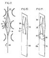
- FIGS. 9 to 12 make it possible, on the contrary, to carry out measurements within the assembly itself.
- FIG. 9 and 10 schematically show a first embodiment.
- a measuring head 28 is carried by a blade 68 which will be designated later by the term "saber".
- This head can have a constitution similar to that shown in FIG. 4.
- the distance available between two layers will often be insufficient to allow the reference coil 16a to be accommodated there in addition to the measurement coil 16.
- the reference coil is then transferred to a part of the saber 68 which remains permanently outside the fuel assembly.
- the sword 68 has a thickness sufficiently small to be able to pass between two layers of pencils 20. It is made of a material having an electrical resistance appreciably higher than that of the sheaths of the pencils.
- a saber 68 made of insulating material, such as a reinforced synthetic resin, or a stainless alloy such as an "inconel 718".
- the saber 68 has a solid part and an end part in which are formed slots delimiting a central sector 70 carrying the head 28, possibly by means of an insulating washer 72, and two lateral sectors 74.
- the central sector 70 has a curvature in the opposite direction to that of the lateral sectors.
- the camber at rest of the sectors is such that the probe, located in the middle of the sector 70, bears against the rods and follows their profile when the saber 68 is moved in the direction of the arrow f1 or in the opposite direction.
- the material of the saber is chosen so that the sectors are compressed elastically when necessary so that the probe can slide between rods 20 whose spacing is less than the nominal spacing, as indicated for example in phantom in FIG. 9.
- the shape at rest of the sectors is such that the head 28 remains firmly applied against the rods 20 even for the maximum possible distance between the facing surfaces of the rods.
- the saber 68a is in two parts: it comprises a blade 76, for example made of flexible insulating material, and a terminal section 78 identical to that shown in FIG. 9 and 10, which can be in "inconel" fixed to the blade by rivets 80.
- FIG. 12 shows a possible mounting of the saber according to FIG. 9 or 10 in a device allowing calibration by comparison with calibration tubes.
- the device of FIG. 12 also comprises a table with crossed movements having a plate 52 which can be moved in x and y .
- the saber 68 is mounted on the plate, where on a plate fixed to the plate, by means allowing adjustment of the saber position and having a safety function.
- the means shown can be viewed as comprising a safety block 82, limiting the forces on the saber, mounted on the plate 26, and a clamp 84 for connecting the saber 68 with the safety block.
- the gripper 84 is a part having a rod 86 for connection with the safety block and a fork for receiving a saber holder 88 in two parts.
- Four adjusting and locking screws 90 make it possible to adjust the orientation and the position of the saber 68 precisely.
- the safety block 82 limits the forces exerted on the saber in the direction x of scanning of the pencils 20. It comprises a casing 91 delimiting a housing in which a flange 92 of the rod 86 can slide.
- the casing 91 is fixed to the plate 26 by any means, such as screws 94.
- It contains a spring 96 which tends to keep the flange 92 in the maximum projecting position where it is shown in FIG. 12.
- the spring 96 is calibrated so as to compress when the force of penetration which is exerted on the rod 86 exceeds a determined threshold, fixed as a function of the maximum tolerable force on the probe and the saber.
- the end of the rod 86 is in abutment against a contactor 98 so that any depression of the rod from the position shown in FIG. 12 opens the contactor 98, placed in a safety circuit which then causes the displacement 26 to stop in the x direction.
- the safety block will generally be supplemented by additional contacts controlled by the saber or the plate 52, preventing any movement in the y and z directions when the saber 68 is engaged between the rods 20.
- the probe can, as in the case of FIGS. 5a and 5b, be calibrated by comparison with several sections of sheath 60 carrying different and known oxide thicknesses, ranging for example from 10 to 100 ⁇ m, and a section of non-oxidized sheath 100 defining an initial reference point.
- the sheath sections 60 and 100, as well as false sheath sections 102 aligned parallel to the first ones and intended to cause a calibration under conditions representative of those encountered by the probe inside the assembly, are carried by a support. 104 fixed in the x direction, but movable in the z and y directions to allow a new calibration before each series of measurements on a sheet.
- the support 104 is placed between the assembly 62 to be checked and the plate 26, the rods 60 being in the extension of the sheet of rods 20 to be checked.
- the saber 68 then has a length sufficient for the measurement probe 13 to be able to sweep successively the sections of calibration sheaths and the pencil sheaths 20 to be checked.
- the reference coil 16a can be placed in the immediate vicinity of the clamp 84.
- the probe 13 is firstly brought to altitude z where the measurement must be made, in line with a space between two layers, by manual control of the vertical displacement in z , then the transverse movement in y .
- the saber 68 is advanced until the probe is opposite the first sheath section 100, by manual control in the direction x . If necessary, a balancing of the measurement circuit is then carried out.
- the following sequence of operations can be fully automatic, following the initiation of a saber driving movement in the x direction. There is successively calibration by scanning the sections of sheath 60 and memorizing the results, then remeasuring over the entire row of pencils.
- the latter is withdrawn, automatically or following a manual command, with possibly a new measurement and / or a new calibration.
Landscapes
- Physics & Mathematics (AREA)
- General Physics & Mathematics (AREA)
- Measurement Of Length, Angles, Or The Like Using Electric Or Magnetic Means (AREA)
- Monitoring And Testing Of Nuclear Reactors (AREA)
Claims (10)
- Verfahren zum Messen des Abstands zwischen etwa parallel zueinander verlaufenden Metallrohren (20), die eine Schicht bilden mittels Foucault-Strömen,
dadurch gekennzeichnet,
daß zur gleichzeitigen Messung der Oxidschichtdicke, die die Rohre bedeckt, eine Foucault-Stromsonde (13) parallel zur Schicht bewegt wird, indem während die Sonde auf die Rohre aufgedrückt wird, ein elektrisches Signal registriert wird, das von der Sonde geliefert wird und die Änderung der Impedanz der Sonde wiedergibt, der Abstand zwischen den Rohren aus der Messung der Bewegung der Sonde zwischen Werten, die aufeinanderfolgenden Impedanzextrema entsprechen, abgeleitet wird und die Oxidschichtdicke auf jedem Rohr aus einem Vergleich zwischen dem jeweiligen Extremwert und mindestens einem Wert gewonnen wird, der durch Messung auf einem Eichrohr erhalten wird, das eine vorbestimmte und bekannte Oxidschichtdicke aufweist. - Verfahren nach Anspruch 1,
gekennzeichnet durch
einen Schritt, der darin besteht die Sonde auf einer Eichrohrschicht zu bewegen, wobei die Eichrohre unterschiedliche Oxidschichtdicken haben, die sich im Bereich der zu messenden Oxidschichtdicken bewegen. - Vorrichtung zur Messung des Abstandes zwischen Metallrohren (20), die in etwa parallel zueinander sind und eine Schicht bilden mittels einer Foucault-Stromsonde (13),
dadurch gekennzeichnet,
daß zur gleichzeitigen Messung der Oxidschichtdicke auf den Rohren die Vorrichtung ferner aufweist: Mittel (26) zum Bewegen der Sonde in eine bestimmte Richtung und zum Messen der Bewegung der Sonde, wobei die Sonde Mittel (24) aufweist, mit der sie elastisch und transversal zur Bewegungsrichtung zurückgeschoben wird und auf die Rohre (20), denen die Sonde begegnet, angedrückt wird, Meßorgane (34-38), die ein Signal in Abhängigkeit von der Impedanz der Sonde liefern, Signalverarbeitungsmittel (40-50), die es erlauben die Extrema des Signals zu bestimmen und die Lage der Sonde entsprechend den Extrema und Mittel zur Berechnung der Schichtdicke der isolierenden Oberflächenschicht durch Vergleich zwischen den Extrema und mindestens einem Wert, der einer vorbestimmten und bekannten Schichtdicke entspricht. - Vorrichtung nach Anspruch 3,
gekennzeichnet durch
einen xy-Tisch (26) mit einer Platte (54), auf der die Sonde mit Hilfe von Organen befestigt ist, die es ermöglichen die Sonde elastisch in einer der Bewegungsrichtungen des Tischs (26) zurückzudrücken, wobei die Platte ferner auf dem xy-Tisch über Organe (58) beweglich ist, die es ermöglichen die Sonde (13) auf mehreren parallel zueinander verlaufenden Eichrohren (60) zu bewegen, die vorbestimmte und bekannte Oxidschichtdicken aufweisen und die es erlauben die Sonde in eine Meßstellung zu bringen, in der sie parallel zur Bewegungsrichtung ausgerichtet ist. - Vorrichtung nach Anspruch 3 oder 4,
dadurch gekennzeichnet,
daß die Sonde (13) in einen Kopf eingebaut ist, der einen kegelstumpfförmigen Endbereich aufweist derart, daß die Sonde dem Profil der Rohre während ihrer Bewegung parallel zur Schicht verfolgt. - Vorrichtung nach Anspruch 5,
dadurch gekennzeichnet,
daß der Kopf eine Referenzwicklung (16a) aufweist, die ein Feld erzeugt, deren Kraftlinien einen Rohrabschnitt (20a) durchqueren, der nicht oxidiert ist und in den Kopf (28) eingelassen ist und eine Eichreferenz darstellt und dadurch, daß die Vorrichtung Mittel zum Messen der Ausgangssignale der Wicklung der Meßsonde und der Referenzwicklung durch Vergleich mißt. - Vorrichtung nach Anspruch 4,
dadurch gekennzeichnet,
daß eine Platte derart auf dem Tisch befestigt ist, daß sie um eine Achse parallel zu den Eichrohren drehbar ist, die auf einer Zylindermantelschicht, die auf der Drehachse der Plattform zentriert ist, angeordnet ist. - Vorrichtung nach Anspruch 3,
gekennzeichnet durch
eine Klinge (68) geringer Dicke, mit einem Endbereich, in dem ein mittlerer Abschnitt (70) abgegrenzt ist, der die Sonde (13) trägt und zwei seitliche Abschnitte (74), wobei der mittlere Abschnitt (70) eine Krümmung aufweist, die der der äußeren Abschnitte entgegengesetzt ist. - Vorrichtung nach Anspruch 8,
dadurch gekennzeichnet,
daß die Klinge auf dem xy-Tisch über Mittel befestigt ist, die eine Justierung der Lage der Klinge ermöglicht und die Funktion eines Kraftbegrenzers erfüllen. - Vorrichtung nach Anspruch 8 oder 9,
gekennzeichnet durch
eine Reihe von Eichrohrabschnitten, mit unterschiedlichen und bekannten Oxidschichtdicken und einer Reihe unechter Brennstababschnitte, die parallel zu den ersten Abschnitten angeordnet sind, wobei der Abstand zwischen den Reihen mit der Klinge ausgerichtet ist und die Eichrohrabschnitte gegenüber der Sonde angeordnet sind.
Applications Claiming Priority (2)
| Application Number | Priority Date | Filing Date | Title |
|---|---|---|---|
| FR8917261 | 1989-12-27 | ||
| FR8917261A FR2656415B1 (fr) | 1989-12-27 | 1989-12-27 | Procede et dispositif de mesure simultanee de distance entre tubes metalliques et d'epaisseur d'oxyde sur les tubes. |
Publications (2)
| Publication Number | Publication Date |
|---|---|
| EP0435757A1 EP0435757A1 (de) | 1991-07-03 |
| EP0435757B1 true EP0435757B1 (de) | 1994-03-30 |
Family
ID=9389017
Family Applications (1)
| Application Number | Title | Priority Date | Filing Date |
|---|---|---|---|
| EP90403710A Expired - Lifetime EP0435757B1 (de) | 1989-12-27 | 1990-12-20 | Verfahren und Vorrichtung zur gleichzeitigen Messung des Abstandes zwischen metallischen Tuben und der Oxyde-Dicke auf den Tuben |
Country Status (5)
| Country | Link |
|---|---|
| US (1) | US5124641A (de) |
| EP (1) | EP0435757B1 (de) |
| JP (1) | JPH05180607A (de) |
| DE (1) | DE69007762T2 (de) |
| FR (1) | FR2656415B1 (de) |
Families Citing this family (21)
| Publication number | Priority date | Publication date | Assignee | Title |
|---|---|---|---|---|
| IT1252413B (it) * | 1991-07-04 | 1995-06-14 | Marposs Spa | Apparecchiatura e metodo per il controllo di pezzi meccanici a simmetria di rotazione |
| FR2700008B1 (fr) * | 1992-12-28 | 1995-03-17 | Framatome Sa | Dispositif de contrôle non destructif d'une surface accessible par un passage de dimension réduite et en particulier de la surface intérieure d'un adaptateur d'un réacteur nucléaire. |
| US5371462A (en) * | 1993-03-19 | 1994-12-06 | General Electric Company | Eddy current inspection method employing a probe array with test and reference data acquisition and signal processing |
| US5341678A (en) * | 1993-05-12 | 1994-08-30 | General Electric Company | Method for determining thickness of ferromagnetic material deposition on nuclear fuel rods |
| US5297174A (en) * | 1993-05-26 | 1994-03-22 | Westinghouse Electric Corp. | Safety system grade apparatus and method for detecting a dropped control rod and malfunctioning exit thermocouples in a pressurized water reactor |
| US5623427A (en) * | 1994-09-02 | 1997-04-22 | Defelsko Corporation | Nondestructive anodic capacity gauge |
| US5821747A (en) * | 1997-01-08 | 1998-10-13 | Queen's University At Kingston | Method and apparatus for scanning a plurality of parallel pipes for flaws using tube-to-tube through transmissions |
| US5744952A (en) * | 1997-02-25 | 1998-04-28 | Mcdermott Technology, Inc. | Eddy current measurement of tube element spacing |
| US6456069B1 (en) * | 1999-03-05 | 2002-09-24 | The United States Of America As Represented By The Secretary Of The Navy | Fluxgate magnetic field sensor incorporating ferromagnetic test material into its magnetic circuitry |
| EP1244907A1 (de) * | 1999-12-23 | 2002-10-02 | KLA-Tencor Corporation | Vor-ort-überwachung für metallisationsprozesse unter verwendung von wirbelstrommessungen und optischen messungen |
| FR2818736B1 (fr) * | 2000-12-22 | 2003-03-28 | Framatome Anp | Procede et dispositif de mesure de l'epaisseur d'une couche d'oxyde sur la gaine de crayons dans un assemblage de combustible |
| DE10102303C1 (de) * | 2001-01-19 | 2002-08-22 | Framatome Anp Gmbh | Meßsystem zur Ermittlung der Schichtdicke einer Oxidschicht |
| DE10123975A1 (de) * | 2001-05-17 | 2002-12-05 | Framatome Anp Gmbh | Meßkopf, insbesondere zum Einsatz bei der Vermessung eines Brennstabs, eines Brennelementkastens und/oder eines Abstandshalters oder sonstige Strukturteile in einem Brennelement einer kerntechnischen Anlage |
| US6895066B1 (en) | 2001-05-17 | 2005-05-17 | Framatome Anp Gmbh | Measuring head and measuring assembly for a nuclear fuel rod |
| DE102005054593B4 (de) * | 2005-11-14 | 2018-04-26 | Immobiliengesellschaft Helmut Fischer Gmbh & Co. Kg | Messonde zur Messung der Dicke dünner Schichten |
| CA2664018C (en) * | 2006-09-21 | 2018-02-20 | Shell Internationale Research Maatschappij B.V. | Device and method for detecting an anomaly in an assembly of a first and a second object |
| CN101465168B (zh) * | 2007-12-21 | 2011-06-22 | 中核北方核燃料元件有限公司 | 涡流水隙测量仪 |
| TW201003672A (en) * | 2008-06-09 | 2010-01-16 | Westinghouse Electric Sweden | Method comprising measurement on fuel channels of fuel assemblies for nuclear boiling water reactors |
| CN101587096B (zh) * | 2009-03-16 | 2011-11-23 | 林俊明 | 一种对不锈钢管内氧化皮厚度分布进行无损检测的方法 |
| US8903680B2 (en) * | 2010-12-10 | 2014-12-02 | The Boeing Company | Apparatus and method for evaluating layers in a multi-layer structure |
| CN114252004B (zh) * | 2021-12-09 | 2023-11-17 | 中国船舶重工集团公司第七0三研究所 | 一种基于电阻测量的套齿齿侧间隙测量装置及方法 |
Family Cites Families (12)
| Publication number | Priority date | Publication date | Assignee | Title |
|---|---|---|---|---|
| US3225294A (en) * | 1961-09-29 | 1965-12-21 | Robert W Mcclung | Method and apparatus for measuring the space between surfaces or objects |
| FR2494837A1 (fr) * | 1980-11-26 | 1982-05-28 | Commissariat Energie Atomique | Dispositif de controle des dimensions et de l'ecartement de pieces rigides disposees en faisceau |
| US4625165A (en) * | 1981-09-28 | 1986-11-25 | Samuel Rothstein | Tube inspection probe with rotating eddy current coil |
| JPS5967405A (ja) * | 1982-09-30 | 1984-04-17 | Sumitomo Metal Ind Ltd | ライナ厚測定方法 |
| US4864239A (en) * | 1983-12-05 | 1989-09-05 | General Electric Company | Cylindrical bearing inspection |
| JPS6138503A (ja) * | 1984-07-31 | 1986-02-24 | Ketsuto Kagaku Kenkyusho:Kk | 膜厚計 |
| KR940002989B1 (ko) * | 1984-10-15 | 1994-04-09 | 지멘스 악티엔게젤샤프트 | 손상된 연료봉 탐지 방법 및 장치 |
| DE3532654A1 (de) * | 1985-09-13 | 1987-03-26 | Thyssen Industrie | Oberflaechenpruefeinrichtung mit konturnachform-fuehrungssystem |
| US4810964A (en) * | 1986-01-22 | 1989-03-07 | Kamyr Ab | Method and apparatus for measuring the distance between a measuring transducer and an opposing surface, particularly with paper pulp equipment |
| US4814703A (en) * | 1987-08-04 | 1989-03-21 | The Boeing Company | Method and apparatus for gap measurement between a graphite/epoxy structure and a metallic model |
| US4862079A (en) * | 1987-11-16 | 1989-08-29 | Westinghouse Electric Corp. | Magnetic method and apparatus for measuring and locating wear of control rods in nuclear reactors |
| GB8808261D0 (en) * | 1988-04-08 | 1988-05-11 | Kineron Gauging Systems Ltd | Thickness measurement device |
-
1989
- 1989-12-27 FR FR8917261A patent/FR2656415B1/fr not_active Expired - Fee Related
-
1990
- 1990-12-20 EP EP90403710A patent/EP0435757B1/de not_active Expired - Lifetime
- 1990-12-20 DE DE69007762T patent/DE69007762T2/de not_active Expired - Fee Related
- 1990-12-27 JP JP2414941A patent/JPH05180607A/ja not_active Withdrawn
- 1990-12-27 US US07/634,532 patent/US5124641A/en not_active Expired - Fee Related
Also Published As
| Publication number | Publication date |
|---|---|
| DE69007762D1 (de) | 1994-05-05 |
| JPH05180607A (ja) | 1993-07-23 |
| FR2656415B1 (fr) | 1993-04-09 |
| DE69007762T2 (de) | 1994-07-28 |
| US5124641A (en) | 1992-06-23 |
| FR2656415A1 (fr) | 1991-06-28 |
| EP0435757A1 (de) | 1991-07-03 |
Similar Documents
| Publication | Publication Date | Title |
|---|---|---|
| EP0435757B1 (de) | Verfahren und Vorrichtung zur gleichzeitigen Messung des Abstandes zwischen metallischen Tuben und der Oxyde-Dicke auf den Tuben | |
| EP0080418B1 (de) | Verfahren und Einrichtung zur Prüfung eines Brennelementbündels eines Kernreaktors | |
| EP0074877B1 (de) | System für die nicht-destruktive Prüfung der Innerstruktur von Objekten | |
| EP0187094B2 (de) | Berührungsloses Wirbelstromprüfverfahren und Vorrichtung zur Durchführung dieses Verfahrens | |
| FR2534015A1 (fr) | Procede et appareil de mesure de l'epaisseur d'un revetement de zirconium sur un tube en alliage de zirconium | |
| EP2742317B1 (de) | Instrument zur längenmessung sowie verfahren und vorrichtung zur kontrolle der grösse eines brennstabes | |
| FR2569598A1 (fr) | Systeme de palpeur equipe d'un doigt | |
| CA1080369A (en) | Scanning electron microscope micrometer scale and method of fabricating same | |
| FR2717893A1 (fr) | Procédé et dispositif pour la mesure de filets coniques. | |
| EP0146091A2 (de) | Verfahren und System zur zerstörungsfreien Prüfung durch Wirbelströme unter Verwendung von überstreichenden Frequenzen | |
| CH422359A (fr) | Dispositif de mesure précise des profils de droites | |
| EP0812419B1 (de) | Verfahren und vorrichtung zum kontrolle von röhren mittels wirbelströmen | |
| EP0766265A2 (de) | Verfahren und Vorrichtung zum Messen mindestens einer charakterisierenden Länge eines Brennstabs an der Peripherie eines Kernbrennstabbündels | |
| EP1817601B1 (de) | Verfahren und vorrichtung zur messung der wasserstoffkonzentration in zirkoniumlegierungskomponenten im brennstoffbecken eines kernkraftwerkes | |
| CN110017788B (zh) | 基于激光测距的电缆压痕自动测试方法 | |
| US2994032A (en) | Inspection system and method | |
| EP0929791A1 (de) | Verfahren und vorrichtung zur messung der verformung von führungsrohren | |
| EP1733205B1 (de) | Verfahren und system zur bestimmung von massedichte und abmessungsmerkmalen eines gegenstands sowie dessen verwendung zur überwachung von kernbrennstoffpellets während deren herstellung | |
| EP0227767A1 (de) | Verfahren und gerät zur volumen-bestimmung des magnetkomponentengehaltes eines materials | |
| FR3116619A1 (fr) | Outillage de support d’eprouvettes pour un controle par tomographie | |
| EP0329531A1 (de) | Verfahren und Vorrichtung zur Abschätzung der Parameter eines geometrischen Modells für einen Manipulator | |
| EP0075517B1 (de) | Vorrichtung zur nicht-destruktiven Messung der Wanddicke eines hohlen Werkstücks | |
| FR2468441A1 (fr) | Procede de reproduction ou de controle d'une piece a partir d'un modele, et dispositif pour sa mise en oeuvre | |
| FR2772121A1 (fr) | Dispositif permettant de determiner la position d'un ensemble mobile de sondes de mesure | |
| FR3095770A1 (fr) | Système et procédé de retaillage de la surface de roulage d’une roue |
Legal Events
| Date | Code | Title | Description |
|---|---|---|---|
| PUAI | Public reference made under article 153(3) epc to a published international application that has entered the european phase |
Free format text: ORIGINAL CODE: 0009012 |
|
| AK | Designated contracting states |
Kind code of ref document: A1 Designated state(s): BE DE SE |
|
| 17P | Request for examination filed |
Effective date: 19911008 |
|
| 17Q | First examination report despatched |
Effective date: 19930323 |
|
| GRAA | (expected) grant |
Free format text: ORIGINAL CODE: 0009210 |
|
| AK | Designated contracting states |
Kind code of ref document: B1 Designated state(s): BE DE SE |
|
| REF | Corresponds to: |
Ref document number: 69007762 Country of ref document: DE Date of ref document: 19940505 |
|
| EAL | Se: european patent in force in sweden |
Ref document number: 90403710.8 |
|
| PLBE | No opposition filed within time limit |
Free format text: ORIGINAL CODE: 0009261 |
|
| STAA | Information on the status of an ep patent application or granted ep patent |
Free format text: STATUS: NO OPPOSITION FILED WITHIN TIME LIMIT |
|
| 26N | No opposition filed | ||
| PGFP | Annual fee paid to national office [announced via postgrant information from national office to epo] |
Ref country code: BE Payment date: 19981216 Year of fee payment: 9 |
|
| PGFP | Annual fee paid to national office [announced via postgrant information from national office to epo] |
Ref country code: SE Payment date: 19981218 Year of fee payment: 9 Ref country code: DE Payment date: 19981218 Year of fee payment: 9 |
|
| PG25 | Lapsed in a contracting state [announced via postgrant information from national office to epo] |
Ref country code: SE Free format text: LAPSE BECAUSE OF NON-PAYMENT OF DUE FEES Effective date: 19991221 |
|
| PG25 | Lapsed in a contracting state [announced via postgrant information from national office to epo] |
Ref country code: BE Free format text: LAPSE BECAUSE OF NON-PAYMENT OF DUE FEES Effective date: 19991231 |
|
| BERE | Be: lapsed |
Owner name: CIE GENERALE DES MATIERES NUCLEAIRES COGEMA Effective date: 19991231 Owner name: FRAMATOME Effective date: 19991231 |
|
| EUG | Se: european patent has lapsed |
Ref document number: 90403710.8 |
|
| PG25 | Lapsed in a contracting state [announced via postgrant information from national office to epo] |
Ref country code: DE Free format text: LAPSE BECAUSE OF NON-PAYMENT OF DUE FEES Effective date: 20001003 |