EP0435757B1 - Method and device for measuring simultaneously the gap between metallical tubes and the thickness of oxyde on the tubes - Google Patents
Method and device for measuring simultaneously the gap between metallical tubes and the thickness of oxyde on the tubes Download PDFInfo
- Publication number
- EP0435757B1 EP0435757B1 EP90403710A EP90403710A EP0435757B1 EP 0435757 B1 EP0435757 B1 EP 0435757B1 EP 90403710 A EP90403710 A EP 90403710A EP 90403710 A EP90403710 A EP 90403710A EP 0435757 B1 EP0435757 B1 EP 0435757B1
- Authority
- EP
- European Patent Office
- Prior art keywords
- probe
- tubes
- measurement
- oxide
- thickness
- Prior art date
- Legal status (The legal status is an assumption and is not a legal conclusion. Google has not performed a legal analysis and makes no representation as to the accuracy of the status listed.)
- Expired - Lifetime
Links
Images

Classifications
-
- G—PHYSICS
- G01—MEASURING; TESTING
- G01B—MEASURING LENGTH, THICKNESS OR SIMILAR LINEAR DIMENSIONS; MEASURING ANGLES; MEASURING AREAS; MEASURING IRREGULARITIES OF SURFACES OR CONTOURS
- G01B7/00—Measuring arrangements characterised by the use of electric or magnetic techniques
- G01B7/02—Measuring arrangements characterised by the use of electric or magnetic techniques for measuring length, width or thickness
- G01B7/06—Measuring arrangements characterised by the use of electric or magnetic techniques for measuring length, width or thickness for measuring thickness
- G01B7/10—Measuring arrangements characterised by the use of electric or magnetic techniques for measuring length, width or thickness for measuring thickness using magnetic means, e.g. by measuring change of reluctance
- G01B7/105—Measuring arrangements characterised by the use of electric or magnetic techniques for measuring length, width or thickness for measuring thickness using magnetic means, e.g. by measuring change of reluctance for measuring thickness of coating
-
- G—PHYSICS
- G01—MEASURING; TESTING
- G01B—MEASURING LENGTH, THICKNESS OR SIMILAR LINEAR DIMENSIONS; MEASURING ANGLES; MEASURING AREAS; MEASURING IRREGULARITIES OF SURFACES OR CONTOURS
- G01B7/00—Measuring arrangements characterised by the use of electric or magnetic techniques
- G01B7/02—Measuring arrangements characterised by the use of electric or magnetic techniques for measuring length, width or thickness
- G01B7/06—Measuring arrangements characterised by the use of electric or magnetic techniques for measuring length, width or thickness for measuring thickness
- G01B7/10—Measuring arrangements characterised by the use of electric or magnetic techniques for measuring length, width or thickness for measuring thickness using magnetic means, e.g. by measuring change of reluctance
-
- G—PHYSICS
- G01—MEASURING; TESTING
- G01B—MEASURING LENGTH, THICKNESS OR SIMILAR LINEAR DIMENSIONS; MEASURING ANGLES; MEASURING AREAS; MEASURING IRREGULARITIES OF SURFACES OR CONTOURS
- G01B7/00—Measuring arrangements characterised by the use of electric or magnetic techniques
- G01B7/14—Measuring arrangements characterised by the use of electric or magnetic techniques for measuring distance or clearance between spaced objects or spaced apertures
Definitions
- the present invention relates to the measurement of the distance between substantially parallel metal tubes constituting a sheet and of the thickness of oxide possibly covering the tubes. It finds a particularly important, although not exclusive, application in the measurement of the distance between the metal tubes constituting the sheaths of rods belonging to nuclear fuel assemblies and the thickness of oxide covering these tubes.
- the reduction in spacing can in particular be caused by an arcuate or banana deformation of certain pencils, locally reducing the spacing between surfaces facing the sheaths.
- the reduction can generate hot spots and lead to the piercing of the sheaths, especially when they come into contact. Even if the consequences are not as serious, the variations in spacing create refrigerant circulation faults and disturb the thermodynamic cycle in a manner detrimental to the proper functioning of the reactor.
- the probe consists of a corner carrying a coil, which is inserted more or less deeply between the tubes, according to their spacing (US-A-3,225,294).
- the thickness of the oxide layer formed on the surface of the sheath in contact with the refrigerant is also desirable to measure the thickness of the oxide layer formed on the surface of the sheath in contact with the refrigerant.
- This oxide layer decreases the heat exchange coefficient between the sheath and the refrigerant and consequently causes the sheath to overheat.
- the claddings made of zirconium-based alloy are progressively covered with a layer of zirconia.
- the thickness of this layer exceeds a limit, of approximately 100 ⁇ m in current pressurized water reactors, the phenomenon of oxide formation tends to get carried away and can lead to cracking of the cladding and therefore to the passage fission products in the refrigerant.
- the spacing between rods of an assembly is generally appreciated by scrolling a camera opposite the gap between rods, along the assembly.
- the camera is equipped with a reference reticle and an operator follows the variations in spacing between the pens on the display screen. This measurement method is painful and its reliability is uncertain.
- the present invention aims to provide a method and a device for simultaneously measuring the distance between substantially parallel metal tubes constituting a sheet, in particular between tubes constituting the sheaths of the rods of a fuel assembly, and the thickness of oxide covering the tubes.
- An accessory object of the invention is to provide a method and a measuring device making it possible to reduce the examination time of an assembly in considerable proportions, in comparison with the prior art.
- it aims to provide a device which can be produced in a form making it possible to measure the spacing and the thicknesses inside an assembly.
- the invention proposes in particular a method of simultaneous measurement of the distance between substantially parallel metal tubes constituting a sheet and of the thickness of oxide covering the tubes, according to claim 1.
- the invention also provides a device making it possible to implement the above-defined method according to claim 3.
- the measuring apparatus comprises a table with crossed displacements carrying a plate on which the probe is mounted by means making it possible to push it elastically in one of the directions of movement of the table, said plate being moreover movable on the table by means making it possible to circulate the probe on several parallel tubes having predetermined oxide thicknesses and known and allowing it to be brought into a measurement position where it is parallel to said direction of movement.
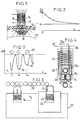
- FIG. 1 shows a fraction of a sheath 10, made of a zirconium-based alloy in general, on which a non-conductive oxide layer 12 has formed.
- An eddy current probe 13 comprises a core of magnetic material 14 carrying a coil 16 to which an electrical voltage at high frequency is applied, generally between 1 and 4 MHz.
- the probe 14 When the probe 14 is in contact with the sheath 10, it induces eddy currents, shown diagrammatically by lines 18, in the conductive part, that is to say in the metal of the sheath.
- the impedance Z of the coil 16 has the appearance shown in FIG. 2: for a zero oxide thickness, the impedance Z of the coil has a maximum value Z O. As the thickness e increases, the apparent impedance decreases and tends asymptotically towards a value Z1. The measurement of the impedance Z in the zone where it varies rapidly with the thickness makes it possible to determine the thickness of the oxide.
- the working frequency will be chosen so as to allow a significant measurement at least up to the maximum tolerable thickness, that is to say approximately 100 ⁇ m in the case of a sheath.
- a frequency of 1.5 MHz will often be satisfactory in the case of zirconium-based alloy sheaths.
- a device for the sequential measurement of the oxide thicknesses on rods 20 of a peripheral fuel assembly sheet without having to raise the probe, to move transversely, then to reapply it at each operation, a device according to the invention comprises a housing 22 in which an eddy current probe 13 is mounted so as to be able to slide parallel to the axis of its coil 16 and elastic means, shown diagrammatically by a spring 24, which tend to bring the probe 13 in the maximum projection position where it is shown in solid lines in FIG. 3.
- the housing 22 is carried by a table with crossed movements 26, making it possible to move it in a direction y parallel to the axis of the probe 13 and an orthogonal direction x .
- the core of the probe 13 (or a head in which this probe is embedded) has a projecting end portion of frustoconical shape, the conicity of which is such that, when the housing 22 is moved in the x direction from the initial position where it is shown in FIG. 3, the probe constitutes a feeler which remains, under the pressure of the spring 24, in permanent contact with the sheaths of the rods 20, and follows their contours.
- the probe 13 comprises a core 14 fixed in the axis of a head 28 made of insulating material, having a frustoconical end portion.
- the core is flush with the end of the head 28.
- It carries the measuring coil 16 which creates a field whose lines of force pass through the sheath of the pencil 20 to be checked.
- It also carries, behind the coil 16, a reference coil 16a which creates a field whose lines of force cross a section of sheath 20a embedded in the head 28, in contact with the core 14 and in alignment with this core.
- This section of sheath represents a reference standard, which is chosen not oxidized.
- the coils 16 and 16a are connected to external circuits, which will be described later, by conductors 30 and 30a.
- a measurement sequence carried out on the rods 20 of a sheet involves bringing the box 22, by displacements in x and y of the table 26 controlled manually, in the position shown in FIG. 3, then actuating the table 26 to move the box in the direction x .
- the head 28 then follows the profile of the pencils 20.
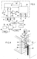
- the external circuits for processing the signal supplied by the probe can have the basic principle shown in FIG. 6. These circuits include an analog part and a digital part.
- the analog part has a generator 32 providing a sinusoidal voltage common reference, for example at 1.5 MHz.
- a differential voltage ⁇ V appears between the coils.
- a differential amplifier 34 amplifies this voltage and applies it to a synchronous detector 36 which also receives, as reference signals, the output voltage of the generator 32 and the same voltage phase shifted by 90 ° by a phase shifter 38.
- the synchronous detector extracts the components X and Y of the vector ⁇ V which are subjected to bandpass filtering in noise reduction filters 38.
- the output signal ⁇ V and the component X exhibit variations as a function of the distance x of the kind shown in FIG. 7.
- the signal X has successive maxima corresponding when the probe passes in the middle of the interval between two successive pencils. These maxima have practically all the same value, given the absence of metallic material in line with the probe at these locations.
- the signal also passes through successive minima V1, V2, V3 when the probe 13 is in line with the generatrices of each of the successive pencils, for positrons x1, x2, x3 of the probe.
- the amplitude of the minima is a direct function of the thickness of oxide present on the sheath.
- this digital part comprises a sampler 40 whose sampling rate is advantageously fixed by a sensor 42 for measuring the displacement in x of the table 26, constituted for example by a digital encoder.
- the increment step of the sensor is chosen according to the resolution desired for the measurement.
- the measurement results can be stored in mass memory 50 (hard disks, floppy disks, etc.) and viewed in real time or in deferred time.
- the measurements can be very precise. Because the measurements are made on the fly, by a simple linear displacement of the table 46, they can be much faster than in the methods according to the prior art.
- the calibration curve of FIG. 2 can be established prior to the measurement of the oxide thicknesses on the rods of a sheet and stored, for the entire duration of the control of an assembly, in cartographic form in RAM 48.
- a more advantageous solution consists in periodically carrying out a verification and possibly an updating of the calibration curve of FIG. 2 between successive measurement sequences. For this, it is possible to use a mounting of the head on the table 26 of the kind shown in FIGS. 5A and 5B.
- a plate 54 On the plate 52, movable along x and y , of the cross-motion table 26 is mounted a plate 54.
- the plate can rotate on the plate 52 around an axis 56 parallel to the axis of the pencils 20 to be checked (axis z ).
- Displacement means shown diagrammatically by a jack 58 interposed between the plate 54 and the plate 52, make it possible to rotate the plate 54 between a measurement position where it is represented in FIG. 5B and calibration positions.
- the plate carries the housing 22 containing a head 28 which can be of the type shown in FIG. 4.
- the axis of the housing 22 and of the probe 13 is directed orthogonally to the sheet of rods 20: when the table 26 is actuated to move the housing 22 in the x direction, the operation is that which has just been described.
- the cross-motion table 26 is controlled so as to release the housing 22 from the pencil ply 20. Then the jack 58 is actuated to move the housing 22 in the direction indicated by the arrow f on the Figure 5A, from the measurement position.
- the plate 52 carries pluselles calibration tubes 60 whose axes are parallel to those of the rods 20 and which are covered with staggered oxide thicknesses, generally from a thin thickness to the maximum thickness to be measured. These tubes 60 can be constituted by sheath sections identical to those of the rods 20, oxidized to known and determined depths.
- sheath sections are arranged according to an arc of a circle, at a distance from the axis 56 such that, in its displacement, the probe of the housing 22 follows them under the conditions where it traverses the sheaths of the pencils 20 during the measurement.
- the oxide thicknesses are for example chosen to correspond to the points indicated in FIG. 2.
- the signal minima obtained are memorized by the computer 44, at the same time as the known thicknesses.
- the calculation of the oxide thicknesses on the sheaths of the rods 20 is then carried out by interpolation, by implementing existing and well-known programs.
- FIG. 8 shows a possible arrangement of a nuclear fuel assembly 62 to be checked and of a measuring device according to the invention.
- the assembly 62 is immersed in a storage pool 64, at a depth sufficient to provide biological protection.
- the device comprises a column 65 on which is mounted a carriage 66 which a motor 67 allows to move vertically, in the direction z .
- This carriage carries the table 26 with crossed movements.
- This device makes it possible to measure the distance between rods and the thickness of oxide on the rods of a peripheral ply occupying one face of the assembly, at more than one level z . We can then rotate the assembly 62 to perform the measurements on the side ply occupying another face.
- the signal processing and movement control circuits can be grouped in a cabinet 69.
- the device described so far only allows the rods belonging to the side plies of an assembly to be verified and this control to be carried out only on the generators directed towards the outside of the assembly.
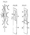
- FIGS. 9 to 12 make it possible, on the contrary, to carry out measurements within the assembly itself.
- FIG. 9 and 10 schematically show a first embodiment.
- a measuring head 28 is carried by a blade 68 which will be designated later by the term "saber".
- This head can have a constitution similar to that shown in FIG. 4.
- the distance available between two layers will often be insufficient to allow the reference coil 16a to be accommodated there in addition to the measurement coil 16.
- the reference coil is then transferred to a part of the saber 68 which remains permanently outside the fuel assembly.
- the sword 68 has a thickness sufficiently small to be able to pass between two layers of pencils 20. It is made of a material having an electrical resistance appreciably higher than that of the sheaths of the pencils.
- a saber 68 made of insulating material, such as a reinforced synthetic resin, or a stainless alloy such as an "inconel 718".
- the saber 68 has a solid part and an end part in which are formed slots delimiting a central sector 70 carrying the head 28, possibly by means of an insulating washer 72, and two lateral sectors 74.
- the central sector 70 has a curvature in the opposite direction to that of the lateral sectors.
- the camber at rest of the sectors is such that the probe, located in the middle of the sector 70, bears against the rods and follows their profile when the saber 68 is moved in the direction of the arrow f1 or in the opposite direction.
- the material of the saber is chosen so that the sectors are compressed elastically when necessary so that the probe can slide between rods 20 whose spacing is less than the nominal spacing, as indicated for example in phantom in FIG. 9.
- the shape at rest of the sectors is such that the head 28 remains firmly applied against the rods 20 even for the maximum possible distance between the facing surfaces of the rods.
- the saber 68a is in two parts: it comprises a blade 76, for example made of flexible insulating material, and a terminal section 78 identical to that shown in FIG. 9 and 10, which can be in "inconel" fixed to the blade by rivets 80.
- FIG. 12 shows a possible mounting of the saber according to FIG. 9 or 10 in a device allowing calibration by comparison with calibration tubes.
- the device of FIG. 12 also comprises a table with crossed movements having a plate 52 which can be moved in x and y .
- the saber 68 is mounted on the plate, where on a plate fixed to the plate, by means allowing adjustment of the saber position and having a safety function.
- the means shown can be viewed as comprising a safety block 82, limiting the forces on the saber, mounted on the plate 26, and a clamp 84 for connecting the saber 68 with the safety block.
- the gripper 84 is a part having a rod 86 for connection with the safety block and a fork for receiving a saber holder 88 in two parts.
- Four adjusting and locking screws 90 make it possible to adjust the orientation and the position of the saber 68 precisely.
- the safety block 82 limits the forces exerted on the saber in the direction x of scanning of the pencils 20. It comprises a casing 91 delimiting a housing in which a flange 92 of the rod 86 can slide.
- the casing 91 is fixed to the plate 26 by any means, such as screws 94.
- It contains a spring 96 which tends to keep the flange 92 in the maximum projecting position where it is shown in FIG. 12.
- the spring 96 is calibrated so as to compress when the force of penetration which is exerted on the rod 86 exceeds a determined threshold, fixed as a function of the maximum tolerable force on the probe and the saber.
- the end of the rod 86 is in abutment against a contactor 98 so that any depression of the rod from the position shown in FIG. 12 opens the contactor 98, placed in a safety circuit which then causes the displacement 26 to stop in the x direction.
- the safety block will generally be supplemented by additional contacts controlled by the saber or the plate 52, preventing any movement in the y and z directions when the saber 68 is engaged between the rods 20.
- the probe can, as in the case of FIGS. 5a and 5b, be calibrated by comparison with several sections of sheath 60 carrying different and known oxide thicknesses, ranging for example from 10 to 100 ⁇ m, and a section of non-oxidized sheath 100 defining an initial reference point.
- the sheath sections 60 and 100, as well as false sheath sections 102 aligned parallel to the first ones and intended to cause a calibration under conditions representative of those encountered by the probe inside the assembly, are carried by a support. 104 fixed in the x direction, but movable in the z and y directions to allow a new calibration before each series of measurements on a sheet.
- the support 104 is placed between the assembly 62 to be checked and the plate 26, the rods 60 being in the extension of the sheet of rods 20 to be checked.
- the saber 68 then has a length sufficient for the measurement probe 13 to be able to sweep successively the sections of calibration sheaths and the pencil sheaths 20 to be checked.
- the reference coil 16a can be placed in the immediate vicinity of the clamp 84.
- the probe 13 is firstly brought to altitude z where the measurement must be made, in line with a space between two layers, by manual control of the vertical displacement in z , then the transverse movement in y .
- the saber 68 is advanced until the probe is opposite the first sheath section 100, by manual control in the direction x . If necessary, a balancing of the measurement circuit is then carried out.
- the following sequence of operations can be fully automatic, following the initiation of a saber driving movement in the x direction. There is successively calibration by scanning the sections of sheath 60 and memorizing the results, then remeasuring over the entire row of pencils.
- the latter is withdrawn, automatically or following a manual command, with possibly a new measurement and / or a new calibration.
Landscapes
- Physics & Mathematics (AREA)
- General Physics & Mathematics (AREA)
- Measurement Of Length, Angles, Or The Like Using Electric Or Magnetic Means (AREA)
- Monitoring And Testing Of Nuclear Reactors (AREA)
Description
La présente invention concerne la mesure de la distance entre tubes métalliques sensiblement parallèles constituant une nappe et de l'épaisseur d'oxyde recouvrant éventuellement les tubes. Elle trouve une application particulièrement importante, bien que non exclusive, dans la mesure de la distance entre les tubes métalliques constituant les gaines de crayons appartenant à des assemblages combustibles nucléaires et de l'épaisseur d'oxyde recouvrant ces tubes.The present invention relates to the measurement of the distance between substantially parallel metal tubes constituting a sheet and of the thickness of oxide possibly covering the tubes. It finds a particularly important, although not exclusive, application in the measurement of the distance between the metal tubes constituting the sheaths of rods belonging to nuclear fuel assemblies and the thickness of oxide covering these tubes.
Lorsque les assemblages combustibles sortis du coeur d'un réacteur après un cycle de fonctionnement ne sont pas complètement épuisés, ils sont rechargés dans le coeur à un autre emplacement. Avant ce rechargement, les assemblages doivent être contrôlés, afin de vérifier que leur état autorise un nouveau passage en réacteur sans risque excessif de rupture de gaines.When the fuel assemblies taken out of the reactor core after an operating cycle are not completely exhausted, they are recharged in the core at another location. Before this reloading, the assemblies must be checked, in order to check that their state allows a new passage in reactor without excessive risk of rupture of sheaths.
Il est notamment nécessaire de vérifier que l'écartement entre crayons adjacents ne s'est pas réduit localement de façon excessive. La réduction d'écartement peut notamment être provoquée par une arcure ou déformation en banane de certains crayons, réduisant localement l'écartement entre surfaces en regard des gaines. La réduction peut générer des points chauds et aboutir au percement des gaines, surtout lorsqu'elles celles-ci arrivent en contact. Même si les conséquences ne sont pas aussi graves, les variations d'écartement créent des défauts de circulation du réfrigérant et perturbent le cycle thermo-dynamique de façon préjudiciable au bon fonctionnement du réacteur.In particular, it is necessary to check that the spacing between adjacent rods has not been excessively reduced locally. The reduction in spacing can in particular be caused by an arcuate or banana deformation of certain pencils, locally reducing the spacing between surfaces facing the sheaths. The reduction can generate hot spots and lead to the piercing of the sheaths, especially when they come into contact. Even if the consequences are not as serious, the variations in spacing create refrigerant circulation faults and disturb the thermodynamic cycle in a manner detrimental to the proper functioning of the reactor.
On connaît déjà un procédé et un dispositif utilisant une sonde à courants de Foucault pour mesurer la distance entre des tubes métalliques. La sonde est constituée par un coin portant une bobine, qui s'insère plus ou moins profondément entre les tubes, suivant leur écartement (US-A-3 225 294).We already know a method and a device using an eddy current probe to measure the distance between metal tubes. The probe consists of a corner carrying a coil, which is inserted more or less deeply between the tubes, according to their spacing (US-A-3,225,294).
Il est également souhaitable de mesurer l'épaisseur de la couche d'oxyde formée a la surface de la gaine en contact avec le réfrigérant. Cette couche d'oxyde diminue le coefficient d'échange thermique entre la gaine et le réfrigérant et provoque en conséquence une surchauffe de la gaine. Dans le cas par exemple des assemblages de combustible pour réacteur nucléaire à eau sous pression, les gaines en alliage à base de zirconium se recouvrent progressivement d'une couche de zircone. Lorsque l'épaisseur de cette couche dépasse une limite, d'environ 100 µm dans les réacteurs à eau sous pression actuels, le phénomène de formation d'oxyde tend à s'emballer et peut conduire à des fissurations de la gaine et donc au passage de produits de fission dans le réfrigérant.It is also desirable to measure the thickness of the oxide layer formed on the surface of the sheath in contact with the refrigerant. This oxide layer decreases the heat exchange coefficient between the sheath and the refrigerant and consequently causes the sheath to overheat. In the case, for example, of fuel assemblies for a pressurized water nuclear reactor, the claddings made of zirconium-based alloy are progressively covered with a layer of zirconia. When the thickness of this layer exceeds a limit, of approximately 100 μm in current pressurized water reactors, the phenomenon of oxide formation tends to get carried away and can lead to cracking of the cladding and therefore to the passage fission products in the refrigerant.
A l'heure actuelle, l'écartement entre crayons d'un assemblage est généralement apprécié en faisant défiler une caméra en face de l'intervalle entre crayons, le long de l'assemblage. La caméra est équipée d'un réticule de référence et un opérateur suit les variations d'écartement entre les crayons sur l'écran de visualisation. Ce mode de mesure est pénible et sa fiabilité est incertaine.At present, the spacing between rods of an assembly is generally appreciated by scrolling a camera opposite the gap between rods, along the assembly. The camera is equipped with a reference reticle and an operator follows the variations in spacing between the pens on the display screen. This measurement method is painful and its reliability is uncertain.
On sait déjà mesurer l'épaisseur d'oxyde en des points déterminés d'une gaine de crayons située à la périphérie d'un assemblage combustible à l'aide d'une sonde à courants de Foucault qui est amenée en contact avec la gaine à examiner, par déplacement orthogonal à la gaine, puis relevée et amenée face au point de mesure suivant (Revue générale nucléaire, Nº3, Mai-Juin 1988, pages 229, article de Van Graeynest et al). Le dispositif destiné à cette mesure n'a pas d'autre fonction. Les mesures dimensionnelles s'effectuent par métrologie classique. Le mode d'amenée de la sonde en chaque point de mesure exige un repérage précis de l'emplacement de la gaine afin que la sonde soit placée radialement : les mesures sont très lentes lorsque l'on souhaite effectuer la mesure en des points suffisamment nombreux et rapprochés.We already know how to measure the oxide thickness at determined points on a rod sheath located at the periphery of a fuel assembly using an eddy current probe which is brought into contact with the sheath. to examine, by displacement orthogonal to the sheath, then raised and brought in front of the next measurement point (General nuclear review, N º 3, May-June 1988, pages 229, article by Van Graeynest et al). The device intended for this measurement has no other function. The dimensional measurements are made by conventional metrology. The mode of bringing the probe to each measurement point requires precise location of the sheath location so that the probe is placed radially: the measurements are very slow when it is desired to perform the measurement at sufficiently numerous points and close together.
La présente invention vise à fournir un procédé et un dispositif permettant de mesurer simultanément la distance entre des tubes métalliques sensiblement parallèles constituant une nappe, notamment entre des tubes constituant les gaines des crayons d'un assemblage combustible, et de l'épaisseur d'oxyde recouvrant les tubes. Un but accessoire de l'invention est de réaliser un procédé et un dispositif de mesure permettant de réduire le temps d'examen d'un assemblage dans des proportions considérables, par comparaison avec l'art antérieur. Elle vise enfin à fournir un dispositif réalisable sous une forme permettant de mesurer l'écartement et les épaisseurs à l'intérieur d'un assemblage.The present invention aims to provide a method and a device for simultaneously measuring the distance between substantially parallel metal tubes constituting a sheet, in particular between tubes constituting the sheaths of the rods of a fuel assembly, and the thickness of oxide covering the tubes. An accessory object of the invention is to provide a method and a measuring device making it possible to reduce the examination time of an assembly in considerable proportions, in comparison with the prior art. Finally, it aims to provide a device which can be produced in a form making it possible to measure the spacing and the thicknesses inside an assembly.
Dans ce but l'invention propose notamment un procédé de mesure simultanée de la distance entre tubes métalliques sensiblement parallèles constituant une nappe et de l'épaisseur d'oxyde recouvrant les tubes, conforme à la revendication 1.To this end, the invention proposes in particular a method of simultaneous measurement of the distance between substantially parallel metal tubes constituting a sheet and of the thickness of oxide covering the tubes, according to claim 1.
L'invention propose également un dispositif permettant de mettre en oeuvre le procédé ci-dessus défini, suivant la revendication 3.The invention also provides a device making it possible to implement the above-defined method according to claim 3.
Dans un premier mode de réalisation de l'appareil, permettant la mesure de la distance entre les gaines de crayons appartenant aux nappes externes d'un assemblage combustible nucléaire, l'appareil de mesure comporte une table à déplacements croisés portant une platine sur laquelle la sonde est montée par des moyens permettant de la repousser élastiquement dans un des sens de déplacement de la table, ladite platine étant de plus déplaçable sur la table par des moyens permettant de faire circuler la sonde sur plusieurs tubes parallèles ayant des épaisseurs d'oxyde prédéterminées et connues et permettant de l'amener dans une position de mesure où elle est parallèle audit sens de déplacement.In a first embodiment of the apparatus, allowing the measurement of the distance between the sheaths of rods belonging to the external layers of a nuclear fuel assembly, the measuring apparatus comprises a table with crossed displacements carrying a plate on which the probe is mounted by means making it possible to push it elastically in one of the directions of movement of the table, said plate being moreover movable on the table by means making it possible to circulate the probe on several parallel tubes having predetermined oxide thicknesses and known and allowing it to be brought into a measurement position where it is parallel to said direction of movement.
L'invention sera mieux comprise à la lecture de la description, qui suit, de modes particuliers de réalisation de l'invention. La description se réfère aux dessins qui l'accompagnent, dans lesquels :
- la figure 1 est un schéma de principe, montrant l'influence d'une couche d'oxyde sur le signal de sortie d'une sonde à courants de Foucault ;
- la figure 2 montre l'allure de la variation du signal d'une sonde appliquée sur un tube en fonction de l'épaisseur d'oxyde sur le tube ;
- la figure 3 est un schéma montrant le déplacement d'une sonde à courants de Foucault lors de la mise en oeuvre du procédé suivant l'invention pour l'examen des crayons appartenant à une nappe latérale d'un assemblage combustible nucléaire ;
- la figure 4 est une vue en coupe montrant une constitution possible de sonde utilisable pour la mise en oeuvre de l'invention, en coupe suivant un plan passant par l'axe d'application contre les crayons à examiner ;
- la figure 5A est une vue schématique en plan de la sonde et de la platine qui la porte, au cours de l'étalonnage ;
- la figure 5B, similaire à la figure 5A, montre la platine dans la position qu'elle occupe lors des opérations de mesure ;
- la figure 6 est un synoptique de principe de la chaîne d'acquisition et de traitement d'un dispositif selon un mode particulier de réalisation de l'invention ;
- la figure 7 montre une courbe représentative des variations du signal analogique de la sonde de mesure ;
- la figure 8 est un schéma montrant une disposition possible d'un assemblage à contrôler et d'un dispositif suivant l'invention, dans une piscine de stockage d'assemblages combustibles irradiés ;
- les figures 9, 10 et 11 sont des schémas montrant, en coupe et en perspective, des têtes de sondes à courants de Foucault permettant d'effectuer des mesures entre nappes de crayons d'un assemblage combustible ;
- la figure 12 est un schéma de principe, en coupe suivant un plan horizontal, montrant l'utilisation d'une tête de mesure du genre montré en figures 9, 10 ou 11 dans un dispositif de mesure.
- Figure 1 is a block diagram showing the influence of an oxide layer on the output signal of an eddy current probe;
- FIG. 2 shows the shape of the variation of the signal of a probe applied to a tube as a function of the thickness of oxide on the tube;
- FIG. 3 is a diagram showing the displacement of an eddy current probe during the implementation of the method according to the invention for examining the rods belonging to a lateral sheet of a nuclear fuel assembly;
- Figure 4 is a sectional view showing a possible constitution of probe usable for the implementation of the invention, in section along a plane passing through the axis of application against the pencils to be examined;
- FIG. 5A is a schematic plan view of the probe and of the plate which carries it, during the calibration;
- FIG. 5B, similar to FIG. 5A, shows the plate in the position it occupies during the measurement operations;
- FIG. 6 is a block diagram of the chain of acquisition and processing of a device according to a particular embodiment of the invention;
- FIG. 7 shows a curve representative of the variations of the analog signal of the measurement probe;
- FIG. 8 is a diagram showing a possible arrangement of an assembly to be checked and of a device according to the invention, in a storage pool for irradiated fuel assemblies;
- FIGS. 9, 10 and 11 are diagrams showing, in section and in perspective, heads of eddy current probes making it possible to carry out measurements between layers of rods of a fuel assembly;
- Figure 12 is a block diagram, in section along a horizontal plane, showing the use of a measuring head of the kind shown in Figures 9, 10 or 11 in a measuring device.
Avant de décrire l'invention, on rappellera les principes d'utilisation d'une sonde à courants de Foucault pour mesurer l'épaisseur d'oxyde sur un tube métallique, tel qu'une gaine de crayon contenant un combustible à l'état d'oxyde, donc non conducteur. La figure 1 montre une fraction d'une gaine 10, en alliage à base de zirconium en général, sur laquelle s'est formée une couche d'oxyde 12 non conductrice. Une sonde à courants de Foucault 13 comporte un noyau en matériau magnétique 14 portant une bobine 16 à laquelle est appliquée une tension électrique à fréquence élevée, généralement comprise entre 1 et 4 MHz. Lorsque la sonde 14 est en contact avec la gaine 10, elle induit des courants de Foucault, schématisés par les lignes 18, dans la partie conductrice, c'est-à-dire dans le métal de la gaine. Ces courants de Foucault créent un champ magnétique inverse qui induit dans la sonde 13, une force contre-électromotrice qui augmente l'impédance apparente de la bobine 16. L'impédance augmente d'autant plus que l'épaisseur de la couche isolante 12 est plus faible donc que la sonde 13 est proche du métal. La relation entre l'impédance Z de la bobine 16 et l'épaisseur e de la couche d'oxyde présente l'allure montrée en figure 2 : pour une épaisseur d'oxyde nulle, l'impédance Z de la bobine a une valeur maximale ZO. Au fur et à mesure que l'épaisseur e augmente, l'impédance apparente diminue et tend de façon asymptotique vers une valeur Z₁. La mesure de l'impédance Z dans la zone où elle varie rapidement avec l'épaisseur, permet de déterminer l'épaisseur d'oxyde. Pour la mise en oeuvre de l'invention, la fréquence de travail sera choisie de façon à autoriser une mesure significative au moins jusqu'à l'épaisseur maximale tolérable, c'est-à-dire 100 µm environ dans le cas d'une gaine. Une fréquence de 1,5 MHz sera souvent satisfaisante en cas de gaines en alliage à base de zirconium.Before describing the invention, the principles of using an eddy current probe to measure the thickness of oxide on a metal tube, such as a pencil sheath containing a fuel in the d state, will be recalled. oxide, therefore non-conductive. FIG. 1 shows a fraction of a sheath 10, made of a zirconium-based alloy in general, on which a
Comme le montre la figure 3, pour la mesure séquentielle des épaisseurs d'oxyde sur des crayons 20 d'une nappe périphérique d'assemblage combustible sans avoir à relever la sonde, à déplacer transversalement, puis à la réappliquer à chaque opération, un dispositif suivant l'invention comprend un boîtier 22 dans lequel une sonde à courants de Foucault 13 est montée de façon à pouvoir coulisser parallèlement à l'axe de sa bobine 16 et des moyens élastiques, schématisés par un ressort 24, qui tendent à amener la sonde 13 dans la position de saillie maximum où elle est représentée en traits pleins sur la figure 3.As shown in FIG. 3, for the sequential measurement of the oxide thicknesses on
Le boîtier 22 est porté par une table à mouvements croisés 26, permettant de le déplacer dans une direction y parallèle à l'axe de la sonde 13 et une direction orthogonale x. Le noyau de la sonde 13 (ou une tête dans laquelle est noyée cette sonde) présente une partie terminale en saillie de forme tronconique, dont la conicité est telle que, lorsque le boîtier 22 est déplacé dans la direction x à partir de la position initiale où il est montré en figure 3, la sonde constitue un palpeur qui reste, sous la pression du ressort 24, en contact permanent avec les gaines des crayons 20, et suit leurs contours.The
Dans un mode avantageux de réalisation, montré en figure 4, la sonde 13 comporte un noyau 14 fixé dans l'axe d'une tête 28 en matériau isolant, ayant une partie terminale tronconique. Le noyau affleure à l'extrémité de la tête 28. Il porte la bobine de mesure 16 qui créée un champ dont les lignes de force traversent la gaine du crayon 20 à contrôler. Il porte également, en arrière de la bobine 16, une bobine de référence 16a qui créée un champ dont les lignes de force traversent un tronçon de gaine 20a noyé dans la tête 28, en contact avec le noyau 14 et en alignement avec ce noyau. Ce tronçon de gaine représente un étalon de référence, qu'on choisit non oxydé. Les bobines 16 et 16a sont reliées à des circuits extérieurs, qui seront décrits plus loin, par des conducteurs 30 et 30a.In an advantageous embodiment, shown in FIG. 4, the
Comme le montre la figure 3, une séquence de mesure effectuée sur les crayons 20 d'une nappe, lors de la mise en oeuvre de l'invention à l'aide du dispositif de la figure 4, implique d'amener le boîtier 22, par des déplacements en x et y de la table 26 commandés manuellement, dans la position montrée en figure 3, puis d'actionner la table 26 pour déplacer le boîtier dans le direction x. La tête 28 suit alors le profil des crayons 20.As shown in FIG. 3, a measurement sequence carried out on the
Les circuits extérieurs d'exploitation du signal fourni par la sonde peuvent avoir la constitution de principe montrée en figure 6. Ces circuits comprennent une partie analogique et une partie numérique. La partie analogique a un générateur 32 fournissant une tension sinusoïdale de référence commune, par exemple à 1,5 MHz. Lorsque la bobine de mesure 16 présente une impédance différente de celle de la bobine de calibrage 16a, une tension différentielle ΔV apparaît entre les bobines. Un amplificateur différentiel 34 amplifie cette tension et l'applique à un détecteur synchrone 36 qui reçoit également, comme signaux de référence, la tension de sortie du générateur 32 et la même tension déphasée de 90° par un déphaseur 38. Le détecteur synchrone extrait les composantes X et Y du vecteur ΔV qui sont soumises à un filtrage passe-bande dans des filtres 38 de réduction du bruit.The external circuits for processing the signal supplied by the probe can have the basic principle shown in FIG. 6. These circuits include an analog part and a digital part. The analog part has a
Dans la pratique, il suffit d'exploiter une des composantes, par exemple la composante X.In practice, it suffices to exploit one of the components, for example the component X.
Lors des déplacements de la tête le long de la nappe de crayons (figure 3) le signal de sortie ΔV et la composante X présentent des variations en fonction de la distance x du genre montré en figure 7. Le signal X a des maxima successifs correspondant au passage de la sonde au milieu de l'intervalle entre deux crayons successifs. Ces maxima ont pratiquement tous la même valeur, étant donné l'absence de matériau métallique au droit de la sonde à ces emplacements. Le signal passe également par des minima successifs V₁, V₂, V₃ lorsque la sonde 13 est au droit des génératrices de chacun des crayons successsifs, pour des positons x₁, x₂, x₃ de la sonde. L'amplitude des minima est directement fonction de l'épaisseur d'oxyde présente sur la gaine.During the movements of the head along the sheet of rods (FIG. 3) the output signal ΔV and the component X exhibit variations as a function of the distance x of the kind shown in FIG. 7. The signal X has successive maxima corresponding when the probe passes in the middle of the interval between two successive pencils. These maxima have practically all the same value, given the absence of metallic material in line with the probe at these locations. The signal also passes through successive minima V₁, V₂, V₃ when the
Le calcul des positions x₁, x₂, x₃ et le calcul des épaisseurs d'oxyde sont effectués par la partie numérique des circuits de mesure. Dans la constitution illustrée en figure 6, cette partie numérique comprend un échantillonneur 40 dont la cadence d'échantillonnage est avantageusement fixée par un capteur 42 de mesure du déplacement en x de la table 26, constituée par exemple par un codeur numérique. Le pas d'incrémentation du capteur est choisi en fonction de la résolution souhaitée pour la mesure.The calculation of the positions x₁, x₂, x₃ and the calculation of the oxide thicknesses are carried out by the digital part of the measurement circuits. In the constitution illustrated in FIG. 6, this digital part comprises a
Les échantillons successifs sont numérisés dans un convertisseur analogique-numérique ou CAN 41, le nombre de niveaux de quantification étant choisi en fonction de la précision souhaitée sur la mesure de l'épaisseur d'oxyde. Dans la pratique, lorsqu'on souhaite une dynamique de 10³ (par exemple pour traiter un signal allant de 0 à 10 volts avec une résolution de 10 mV) une quantification sur 10 bits est nécessaire. On pourra utiliser un CAN du commerce quantifiant chaque échantillon sur 12 bits. Les échantillons numérisés successifs sont appliqués à un calculateur 44 ayant une mémoire de programme 46 et une mémoire vive de travail 48. Le calculateur est programmé pour :
- déterminer, par exemple par dérivation et détermination des passages par zéro, les minima successifs du signal X,
- calculer les positions x₁, x₂, x₃, à partir des indications reçues du capteur de déplacement 42 et en déduire, par soustraction, les distances entre crayons le long du trajet parcouru par la sonde,
- calculer, à partir d'une courbe d'étalonnage (du genre montré en figure 2) également mémorisée, les épaisseurs d'oxyde, à partir des minima V₁, V₂, V₃ etc.
- determining, for example by derivation and determination of zero crossings, the successive minima of the signal X ,
- calculate the positions x₁, x₂, x₃, from the indications received from the
displacement sensor 42 and deduce therefrom, by subtraction, the distances between rods along the path traveled by the probe, - calculate, from a calibration curve (of the kind shown in FIG. 2) also stored, the oxide thicknesses, from the minima V₁, V₂, V₃ etc.
Les résultats de la mesure peuvent être stockés en mémoire de masse 50 (disques durs, disquettes, etc.) et visualisés en temps réel ou en temps différé.The measurement results can be stored in mass memory 50 (hard disks, floppy disks, etc.) and viewed in real time or in deferred time.
Du fait que le signal X prend une valeur minimum lorsque la sonde est exactement alignée avec l'axe du crayon, les mesures peuvent être très précises. Du fait que les mesures s'effectuent à la volée, par un simple déplacement linéaire de la table 46, elles peuvent être beaucoup plus rapides que dans les procédés suivant l'art antérieur.Since the signal X takes a minimum value when the probe is exactly aligned with the axis of the pencil, the measurements can be very precise. Because the measurements are made on the fly, by a simple linear displacement of the table 46, they can be much faster than in the methods according to the prior art.
La courbe de calibrage de la figure 2 peut être établie préalablement à la mesure des épaisseurs d'oxyde sur les crayons d'une nappe et stockée, pour toute la durée du contrôle d'un assemblage, sous forme cartographique en mémoire vive 48. Une solution plus avantageuse consiste à effectuer périodiquement une vérification et éventuellement une mise à jour de la courbe de calibrage de la figure 2 entre des séquences de mesures successives. Pour cela, il est possible d'utiliser un montage de la tête sur la table 26 du genre montré en figure 5A et 5B.The calibration curve of FIG. 2 can be established prior to the measurement of the oxide thicknesses on the rods of a sheet and stored, for the entire duration of the control of an assembly, in cartographic form in
Sur le plateau 52, mobile suivant x et y, de la table à mouvements croisés 26 est montée une platine 54. La platine peut tourner sur le plateau 52 autour d'un axe 56 parallèle à l'axe des crayons 20 à contrôler (axe z). Des moyens de déplacement, schématisés par un vérin 58 interposé entre la platine 54 et le plateau 52, permettent de faire tourner la platine 54 entre une position de mesure où elle est représentée en figure 5B et des positions d'étalonnage. La platine porte le boîtier 22 contenant une tête 28 qui peut être du genre montré en figure 4.On the
Dans la position de mesure montrée, en figure 5B, l'axe du boîtier 22 et de la sonde 13 est dirigé orthogonalement à la nappe de crayons 20 : lorsque la table 26 est mise en action pour déplacer le boîtier 22 dans la direction x, le fonctionnement est celui qui vient d'être décrit.In the measurement position shown in FIG. 5B, the axis of the
Pour étalonner le dispositif, la table à mouvements croisés 26 est commandée de façon à dégager le boîtier 22 de la nappe de crayons 20. Puis le vérin 58 est mis en action pour déplacer le boîtier 22 dans la direction indiquée par la flèche f sur la figure 5A, à partir de la position de mesure. Le plateau 52 porte plusleurs tubes d'étalonnage 60 dont les axes sont parallèles à ceux des crayons 20 et qui sont recouverts d'épaisseurs d'oxyde échelonnées, en règle générale depuis une épaisseur faible jusqu'à l'épaisseur maximale à mesurer. Ces tubes 60 peuvent être constitués par des tronçons de gaine identiques à celles des crayons 20, oxydées sur des profondeurs connues et déterminées. Ces tronçons de gaine sont disposés suivant un arc de cercle, à une distance de l'axe 56 telle que, dans son déplacement, la sonde du boîtier 22 les suit dans les conditions où elle parcourt les gaines des crayons 20 lors de la mesure. Les épaisseurs d'oxyde sont par exemple choisies pour correspondre aux points indiqués sur la figure 2. Les minima de signal obtenus sont mémorisés par le calculateur 44, en même temps que les épaisseurs connues. Le calcul des épaisseurs d'oxyde sur les gaines des crayons 20 s'effectue alors par interpolation, en mettant en oeuvre des programmes existants et bien connus.To calibrate the device, the cross-motion table 26 is controlled so as to release the
La figure 8 montre une disposition possible d'un assemblage combustible nucléaire 62 à contrôler et d'un dispositif de mesure selon l'invention. L'assemblage 62 est immergé dans une piscine de stockage 64, à une profondeur suffisante pour assurer la protection biologique. Le dispositif comprend une colonne 65 sur laquelle est monté un chariot 66 qu'un moteur 67 permet de déplacer verticalement, suivant la direction z. Ce chariot porte la table 26 à mouvements croisés. Ce dispositif permet de mesurer la distance entre crayons et l'épaisseur d'oxyde sur les crayons d'une nappe périphérique occupant une face de l'assemblage, à plusleurs niveaux z. On peut ensuite faire tourner l'assemblage 62 pour réaliser les mesures sur la nappe latérale occupant une autre face. Les circuits d'exploitation de signal et de commande des déplacements peuvent être regroupés dans une armoire 69.FIG. 8 shows a possible arrangement of a
Le dispositif décrit jusqu'ici ne permet de vérifier que les crayons appartenant aux nappes latérales d'un assemblage et de n'effectuer ce contrôle que sur les génératrices dirigées vers l'extérieur de l'assemblage.The device described so far only allows the rods belonging to the side plies of an assembly to be verified and this control to be carried out only on the generators directed towards the outside of the assembly.
Les variantes de réalisation montrées en figures 9 à 12 permettent au contraire d'effectuer des mesures au sein même de l'assemblage.The variant embodiments shown in FIGS. 9 to 12 make it possible, on the contrary, to carry out measurements within the assembly itself.
Les figures 9 et 10 montrent schématiquement une première réalisation. Une tête 28 de mesure est portée par une lame 68 qu'on désignera ultérieurement par le terme de "sabre". Cette tête peut avoir une constitution similaire à celle montrée en figure 4. Cependant la distance disponible entre deux nappes sera souvent insuffisante pour permettre d'y loger la bobine de référence 16a en plus de la bobine de mesure 16. La bobine de référence est alors reportée sur une partie du sabre 68 qui reste en permanence à l'extérieur de l'assemblage combustible. Le sabre 68 a une épaisseur suffisamment faible pour pouvoir passer entre deux nappes de crayons 20. Il est en un matériau ayant une résistance électrique notablement plus élevée que celle des gaines des crayons. Pratiquement, on peut utiliser un sabre 68 en matériau isolant, tel qu'une résine synthétique armée, ou un alliage inoxydable tel qu'un "inconel 718".Figures 9 and 10 schematically show a first embodiment. A measuring
Le sabre 68 a une partie pleine et une partie terminale dans laquelle sont ménagées des fentes délimitant un secteur central 70 portant la tête 28, éventuellement par l'intermédiaire d'une rondelle isolante 72, et deux secteurs latéraux 74. Le secteur central 70 présente une courbure de sens opposée à celle des secteurs latéraux. La cambrure au repos des secteurs est telle que la sonde, située au milieu du secteur 70, s'appuie contre les crayons et suit leur profil lorsqu'on déplace le sabre 68 dans le sens de la flèche f₁ ou en sens contraire.The
Le matériau constitutif du sabre est choisi de façon que les secteurs s'écrasent élastiquement lorsque cela est nécessaire pour que la sonde puisse se glisser entre des crayons 20 dont l'écartement est inférieur à l'écartement nominal, comme indiqué par exemple en traits mixtes sur la figure 9. La forme au repos des secteurs est telle que la tête 28 reste appliquée fermement contre les crayons 20 même pour l'écart maximum possible entre les surfaces en regard des crayons.The material of the saber is chosen so that the sectors are compressed elastically when necessary so that the probe can slide between
Dans le mode de réalisation montré schématiquement en figure 11, le sabre 68a est en deux pièces : il comporte une lame 76, par exemple en matière isolante souple, et un tronçon terminal 78 identique à celui montré en figure 9 et 10, pouvant être en "inconel" fixé à la lame par des rivets 80.In the embodiment shown diagrammatically in FIG. 11, the
D'autres constitutions encore de la partie mécanique du sabre sont possibles, par exemple du genre montré dans le document EP-A-0 178 860, qui toutefois porte une sonde ultra-sonore.Still other constitutions of the mechanical part of the saber are possible, for example of the kind shown in document EP-A-0 178 860, which however carries an ultrasonic probe.
La figure 12 montre un montage possible du sabre suivant la figure 9 ou 10 dans un dispositif permettant un calibrage par comparaison avec des tubes d'étalonnage. Le dispositif de la figure 12 comporte encore une table à mouvements croisés ayant un plateau 52 déplaçable en x et y. Le sabre 68 est monté sur le plateau, où sur une platine fixée au plateau, par l'intermédiaire de moyens permettant un réglage de position du sabre et ayant une fonction de sécurité.FIG. 12 shows a possible mounting of the saber according to FIG. 9 or 10 in a device allowing calibration by comparison with calibration tubes. The device of FIG. 12 also comprises a table with crossed movements having a
Les moyens représentés peuvent être regardés comme comprenant un bloc de sécurité 82, limitant les efforts sur le sabre, monté sur le plateau 26, et une pince 84 de connexion du sabre 68 avec le bloc de sécurité.The means shown can be viewed as comprising a
La pince de préhension 84 est une pièce ayant une tige 86 de liaison avec le bloc de sécurité et une fourche de réception d'un porte sabre 88 en deux pièces. Quatre vis de réglage et de blocage 90 permettent de régler l'orientation et la position du sabre 68 de façon précise.The
Le bloc de sécurité 82 limite les efforts exercés sur le sabre dans la direction x de balayage des crayons 20. Il comprend un carter 91 délimitant un logement dans lequel peut coulisser une collerette 92 de la tige 86. Le carter 91 est fixé au plateau 26 par des moyens quelconques, tels que des vis 94. Il contient un ressort 96 qui tend à maintenir la collerette 92 dans la position de saillie maximum où elle est représentée en figure 12. Le ressort 96 est taré de façon à se comprimer lorsque la force d'enfoncement qui s'exerce sur la tige 86 dépasse un seuil déterminé, fixé en fonction de l'effort maximum tolérable sur la sonde et le sabre. L'extrémité de la tige 86 est en appui contre un contacteur 98 de façon que tout enfoncement de la tige à partir de la position montrée en figure 12 ouvre le contacteur 98, placé dans un circuit de sécurité qui provoque alors l'arrêt du déplacement 26 dans le sens x.The
Le bloc de sécurité sera en général complété par des contacts supplémentaires commandés par le sabre ou le plateau 52, interdisant tout déplacement dans les directions y et z lorsque le sabre 68 est engagé entre les crayons 20.The safety block will generally be supplemented by additional contacts controlled by the saber or the
La sonde peut, comme dans le cas des figures 5a et 5b, être étalonnée par comparaison avec plusieurs tronçons de gaine 60 portant des épaisseurs d'oxyde différentes et connues, allant par exemple de 10 à 100 µm, et un tronçon de gaine non oxydé 100 définissant un point initial de référence. Les tronçons de gaine 60 et 100, ainsi que des tronçons de gaine postiches 102 alignés parallèlement aux premiers et destinés à provoquer un étalonnage dans des conditions représentatives de celles rencontrées par la sonde à l'intérieur de l'assemblage, sont portées par un support 104 fixé dans la direction x, mais déplaçable dans les directions z et y pour permettre un nouvel étalonnage avant chaque série de mesures sur une nappe.The probe can, as in the case of FIGS. 5a and 5b, be calibrated by comparison with several sections of
Dans le mode de réalisation montré en figure 12, le support 104 est placé entre l'assemblage 62 à contrôler et le plateau 26, les crayons 60 étant dans le prolongement de la nappe de crayons 20 à contrôler. Le sabre 68 a alors une longueur suffisante pour que la sonde de mesure 13 puisse balayer successivement les tronçons de gaines de calibrage et les gaines de crayons 20 à contrôler. La bobine de référence 16a peut être placée à proximité immédiate de la pince 84.In the embodiment shown in FIG. 12, the
La séquence des opérations au cours d'un cycle de mesure d'intervalle entre les crayons d'une nappe et de mesure d'épaisseur d'oxyde sont alors les suivantes.The sequence of operations during a cycle for measuring the interval between the rods of a sheet and for measuring the oxide thickness are then as follows.
La sonde 13 est tout d'abord amenée à l'altitude z où doit être effectuée la mesure, au droit d'un espace entre deux nappes, par commande manuelle du déplacement vertical en z, puis du mouvement transversal en y. Le sabre 68 est avancé jusqu'à ce que la sonde soit en face du premier tronçon de gaine 100, par commande manuelle suivant la direction x. Si nécessaire, un équilibrage du circuit de mesure est alors réalisé.The
La séquence suivante d'opérations peut être entièrement automatique, à la suite du déclenchement d'un mouvement d'enfoncement du sabre suivant la direction x. Il y a successivement étalonnage par balayage des tronçons de gaine 60 et mémorisation des résultats, puis remesure sur toute la rangée de crayons.The following sequence of operations can be fully automatic, following the initiation of a saber driving movement in the x direction. There is successively calibration by scanning the sections of
A la fin du mouvement d'avancée du sabre, ce dernier est retiré, de façon automatique ou à la suite d'une commande manuelle, avec éventuellement une nouvelle mesure et/ou un nouvel étalonnage.At the end of the advance movement of the saber, the latter is withdrawn, automatically or following a manual command, with possibly a new measurement and / or a new calibration.
Grâce au dispositif montré sur les figures 9 à 12, il est possible de contrôler les crayons d'un assemblage le long de quatre génératrices et en des points relativement rapprochés dans le sens longitudinal, du fait de la rapidité des mesures. L'utilisation des secteurs flexibles pour porter la sonde permet à cette dernière de se glisser non seulement entre deux gaines, mais aussi entre une gaine et un tube guide du genre rencontré dans les assemblages combustibles existants.Thanks to the device shown in Figures 9 to 12, it is possible to control the rods of an assembly along four generators and at relatively close points in the longitudinal direction, due to the speed of the measurements. The use of flexible sectors to carry the probe allows the latter to slide not only between two sheaths, but also between a sheath and a guide tube of the type encountered in existing fuel assemblies.
Claims (10)
- A method for eddy current measurement of the distance between substantially parallel metal tubes (20) forming a sheet,
characterized in that, for simultaneously measuring the thickness of oxide covering the tubes: an eddy current probe (13) is moved parallel to the sheet while maintaining the probe applied on the tubes; an electric signal delivered by the probe and representing impedance variations of the probe is recorded; the distances between the tubes are derived from measurement of the amounts of displacement of the probe between values of the signal which correspond to successive extremum values of the impedance; and the thickness of oxide on each tube is derived from a comparison between the respective extremum value and at least one value obtained by measurement on a standard tube carrying a predetermined known thickness of oxide. - Method according to claim 1, characterized in that the method includes a step of moving the probe over a sheet of standard tubes having mutually different oxide thicknesses and distributed over a range of oxide thicknesses to be measured.
- Device for measuring, with an eddy current probe (13) the distance between substantially parallel metal tubes (20) forming a sheet,
characterized in that, for simultaneously measuring a thickness of oxide on the tubes, the device further comprises: means (26) for moving the probe along a predetermined direction and for measuring the amounts of movement of the probe, said probe comprising means (24) for resiliently biasing it transversely to the direction of movement and applying it on the encountered tubes (20); measurement means (34-38) for delivering a signal which is responsive to the impedance of the probe; means (40 to 50) for processing the signal and determining the extremum values of said signal and the locations of the probe corresponding to the extremum values; and means for computing the thicknesses of insulating superficial layer by comparing said extremum values with at least one value corresponding to a predetermined known thickness. - Device according to claim 3,
characterized in that it comprises a cross-movement table (26) carrying a platform (54) on which the probe is carried by means for resiliently forcing it in one of the directions of movement of the table (26), said platform being further movable on the table by means (58) for circulating the probe (13) on a plurality of calibration parallel tubes (60) having predetermined known oxide thicknesses and enabling to move it into a measurement position where it is parallel to said direction of movement. - Device according to claim 3 or 4,
characterized in that the probe (13) belongs to a head having a frusto-conical end portion degree of taper that the head follows the profile of the tubes during movements thereof parallel to the sheet. - Device according to claim 5,
characterized in that the head has a reference coil (16a) which generates a field whose field lines traverse a non-oxidized tube section (20a) embedded in the head (28) and constituting a reference standard and in that the device comprises measurement means comparing the output signals of the coil of the measurement probe and of the reference coil. - Device according to claim 4,
characterized in that the platform is carried by the table for rotation about an axis which is parallel to the calibration tubes, which are arranged in a cylindrical row centered on an axis of rotation of the platform on the table. - Device according to claim 3,
characterized in that it comprises a strip (68) of low thickness, having a terminal portion formed with a central sector (70) carrying the probe (13) and with two lateral sectors (74), the central sector being bent in a direction opposite to that of the lateral sectors. - Device according to claim 8,
characterized in that the strip is carried by the cross-movement table through means for adjusting the position of the strip and for force limitation. - Device according to claim 8 or 9,
characterized in that it comprises a row of calibration tube sections carrying layers of oxide having different known thicknesses and a row of dummy tube sections aligned parallel to the first tube sections, the gap between the rows being in alignment with the strip and the calibration tube sections confronting the probe.
Applications Claiming Priority (2)
| Application Number | Priority Date | Filing Date | Title |
|---|---|---|---|
| FR8917261 | 1989-12-27 | ||
| FR8917261A FR2656415B1 (en) | 1989-12-27 | 1989-12-27 | METHOD AND DEVICE FOR SIMULTANEOUSLY MEASURING DISTANCE BETWEEN METAL TUBES AND OXIDE THICKNESS ON TUBES. |
Publications (2)
| Publication Number | Publication Date |
|---|---|
| EP0435757A1 EP0435757A1 (en) | 1991-07-03 |
| EP0435757B1 true EP0435757B1 (en) | 1994-03-30 |
Family
ID=9389017
Family Applications (1)
| Application Number | Title | Priority Date | Filing Date |
|---|---|---|---|
| EP90403710A Expired - Lifetime EP0435757B1 (en) | 1989-12-27 | 1990-12-20 | Method and device for measuring simultaneously the gap between metallical tubes and the thickness of oxyde on the tubes |
Country Status (5)
| Country | Link |
|---|---|
| US (1) | US5124641A (en) |
| EP (1) | EP0435757B1 (en) |
| JP (1) | JPH05180607A (en) |
| DE (1) | DE69007762T2 (en) |
| FR (1) | FR2656415B1 (en) |
Families Citing this family (21)
| Publication number | Priority date | Publication date | Assignee | Title |
|---|---|---|---|---|
| IT1252413B (en) * | 1991-07-04 | 1995-06-14 | Marposs Spa | EQUIPMENT AND METHOD FOR THE CONTROL OF MECHANICAL PIECES WITH ROTATION SYMMETRY |
| FR2700008B1 (en) * | 1992-12-28 | 1995-03-17 | Framatome Sa | Device for non-destructive testing of a surface accessible by a passage of reduced size and in particular of the interior surface of an adapter of a nuclear reactor. |
| US5371462A (en) * | 1993-03-19 | 1994-12-06 | General Electric Company | Eddy current inspection method employing a probe array with test and reference data acquisition and signal processing |
| US5341678A (en) * | 1993-05-12 | 1994-08-30 | General Electric Company | Method for determining thickness of ferromagnetic material deposition on nuclear fuel rods |
| US5297174A (en) * | 1993-05-26 | 1994-03-22 | Westinghouse Electric Corp. | Safety system grade apparatus and method for detecting a dropped control rod and malfunctioning exit thermocouples in a pressurized water reactor |
| US5623427A (en) * | 1994-09-02 | 1997-04-22 | Defelsko Corporation | Nondestructive anodic capacity gauge |
| US5821747A (en) * | 1997-01-08 | 1998-10-13 | Queen's University At Kingston | Method and apparatus for scanning a plurality of parallel pipes for flaws using tube-to-tube through transmissions |
| US5744952A (en) * | 1997-02-25 | 1998-04-28 | Mcdermott Technology, Inc. | Eddy current measurement of tube element spacing |
| US6456069B1 (en) * | 1999-03-05 | 2002-09-24 | The United States Of America As Represented By The Secretary Of The Navy | Fluxgate magnetic field sensor incorporating ferromagnetic test material into its magnetic circuitry |
| WO2001046684A1 (en) * | 1999-12-23 | 2001-06-28 | Kla-Tencor Corporation | In-situ metalization monitoring using eddy current measurements and optical measurements |
| FR2818736B1 (en) * | 2000-12-22 | 2003-03-28 | Framatome Anp | METHOD AND DEVICE FOR MEASURING THE THICKNESS OF AN OXIDE LAYER ON THE PENCIL SHEATH IN A FUEL ASSEMBLY |
| DE10102303C1 (en) * | 2001-01-19 | 2002-08-22 | Framatome Anp Gmbh | Measuring system for determining the layer thickness of an oxide layer |
| DE10123975A1 (en) * | 2001-05-17 | 2002-12-05 | Framatome Anp Gmbh | Measuring head, in particular for use in the measurement of a fuel rod, a fuel assembly box and / or a spacer or other structural parts in a fuel assembly of a nuclear facility |
| US6895066B1 (en) | 2001-05-17 | 2005-05-17 | Framatome Anp Gmbh | Measuring head and measuring assembly for a nuclear fuel rod |
| DE102005054593B4 (en) * | 2005-11-14 | 2018-04-26 | Immobiliengesellschaft Helmut Fischer Gmbh & Co. Kg | Measuring probe for measuring the thickness of thin layers |
| CA2664018C (en) * | 2006-09-21 | 2018-02-20 | Shell Internationale Research Maatschappij B.V. | Device and method for detecting an anomaly in an assembly of a first and a second object |
| CN101465168B (en) * | 2007-12-21 | 2011-06-22 | 中核北方核燃料元件有限公司 | Instrument for measuring eddy flow water gap |
| TW201003672A (en) * | 2008-06-09 | 2010-01-16 | Westinghouse Electric Sweden | Method comprising measurement on fuel channels of fuel assemblies for nuclear boiling water reactors |
| CN101587096B (en) * | 2009-03-16 | 2011-11-23 | 林俊明 | Method for nondestructive examination of oxide thickness distribution in stainless steel tubes |
| US8903680B2 (en) * | 2010-12-10 | 2014-12-02 | The Boeing Company | Apparatus and method for evaluating layers in a multi-layer structure |
| CN114252004B (en) * | 2021-12-09 | 2023-11-17 | 中国船舶重工集团公司第七0三研究所 | Device and method for measuring tooth side gap of sleeve tooth based on resistance measurement |
Family Cites Families (12)
| Publication number | Priority date | Publication date | Assignee | Title |
|---|---|---|---|---|
| US3225294A (en) * | 1961-09-29 | 1965-12-21 | Robert W Mcclung | Method and apparatus for measuring the space between surfaces or objects |
| FR2494837A1 (en) * | 1980-11-26 | 1982-05-28 | Commissariat Energie Atomique | DEVICE FOR CONTROLLING THE DIMENSIONS AND THE SPACING OF RIGID PARTS DISPOSED IN BEAM |
| US4625165A (en) * | 1981-09-28 | 1986-11-25 | Samuel Rothstein | Tube inspection probe with rotating eddy current coil |
| JPS5967405A (en) * | 1982-09-30 | 1984-04-17 | Sumitomo Metal Ind Ltd | Method for measuring thickness of liner |
| US4864239A (en) * | 1983-12-05 | 1989-09-05 | General Electric Company | Cylindrical bearing inspection |
| JPS6138503A (en) * | 1984-07-31 | 1986-02-24 | Ketsuto Kagaku Kenkyusho:Kk | Film thickness gauge |
| KR940002989B1 (en) * | 1984-10-15 | 1994-04-09 | 지멘스 악티엔게젤샤프트 | Method and apparatus for detecting failed fuel rods |
| DE3532654A1 (en) * | 1985-09-13 | 1987-03-26 | Thyssen Industrie | SURFACE TESTING DEVICE WITH CONTOUR MOLDING GUIDE SYSTEM |
| US4810964A (en) * | 1986-01-22 | 1989-03-07 | Kamyr Ab | Method and apparatus for measuring the distance between a measuring transducer and an opposing surface, particularly with paper pulp equipment |
| US4814703A (en) * | 1987-08-04 | 1989-03-21 | The Boeing Company | Method and apparatus for gap measurement between a graphite/epoxy structure and a metallic model |
| US4862079A (en) * | 1987-11-16 | 1989-08-29 | Westinghouse Electric Corp. | Magnetic method and apparatus for measuring and locating wear of control rods in nuclear reactors |
| GB8808261D0 (en) * | 1988-04-08 | 1988-05-11 | Kineron Gauging Systems Ltd | Thickness measurement device |
-
1989
- 1989-12-27 FR FR8917261A patent/FR2656415B1/en not_active Expired - Fee Related
-
1990
- 1990-12-20 EP EP90403710A patent/EP0435757B1/en not_active Expired - Lifetime
- 1990-12-20 DE DE69007762T patent/DE69007762T2/en not_active Expired - Fee Related
- 1990-12-27 JP JP2414941A patent/JPH05180607A/en not_active Withdrawn
- 1990-12-27 US US07/634,532 patent/US5124641A/en not_active Expired - Fee Related
Also Published As
| Publication number | Publication date |
|---|---|
| DE69007762T2 (en) | 1994-07-28 |
| US5124641A (en) | 1992-06-23 |
| FR2656415A1 (en) | 1991-06-28 |
| FR2656415B1 (en) | 1993-04-09 |
| DE69007762D1 (en) | 1994-05-05 |
| JPH05180607A (en) | 1993-07-23 |
| EP0435757A1 (en) | 1991-07-03 |
Similar Documents
| Publication | Publication Date | Title |
|---|---|---|
| EP0435757B1 (en) | Method and device for measuring simultaneously the gap between metallical tubes and the thickness of oxyde on the tubes | |
| EP0080418B1 (en) | Method and device for checking a fuel assembly of a nuclear reactor | |
| EP0074877B1 (en) | System for the non-destructive testing of the internal structure of objects | |
| EP0187094B2 (en) | Contactless eddy current testing method, and apparatus for carrying out this method | |
| FR2534015A1 (en) | METHOD AND APPARATUS FOR MEASURING THE THICKNESS OF A ZIRCONIUM COATING ON A ZIRCONIUM ALLOY TUBE | |
| CA1080369A (en) | Scanning electron microscope micrometer scale and method of fabricating same | |
| EP1817601B1 (en) | Method and apparatus for measuring hydrogen concentration in zirconium alloy components in the fuel pool of a nuclear power plant | |
| EP0146091A2 (en) | Method and system for non-destructive eddy current testing using a frequency sweep | |
| EP0812419B1 (en) | Device and method for eddy current testing of tubes | |
| EP0766265A2 (en) | Method and apparatus for measuring at least one characteristic length of a fuel rod disposed at the periphery of a nuclear fuel assembly | |
| EP1733205B1 (en) | Method and system for determining the mass density and dimensional characteristics of an object, and use thereof for controlling nuclear fuel pellets during the production of the same | |
| EP2742317B1 (en) | Instrument for measuring length, and method and device for controlling the size of a fuel rod | |
| US2994032A (en) | Inspection system and method | |
| EP0929791A1 (en) | Method and device for measuring the deformation of a guide tube | |
| WO2016071624A1 (en) | Device and method for detecting deposits of at least one ferromagnetic material on the outside wall of a tube | |
| CN110017788B (en) | Cable indentation automatic test method based on laser ranging | |
| FR2468441A1 (en) | Pipework model tracer for machine tool programming - uses triple axis tracer with head rotation and computing device to allow programmable detection from minium data | |
| FR2772121A1 (en) | Automatic determination of the position of a movable sensor array | |
| EP0075517A1 (en) | Device for non-destructive measuring of the thickness of the wall of a hollow workpiece | |
| FR2950434A1 (en) | IMPROVEMENTS IN DETECTION OF DEPOSITS COMPRISING AT LEAST ONE FERROMAGNETIC MATERIAL ON OR NEAR THE OUTER WALL OF A TUBE | |
| FR2777817A1 (en) | Spectacle frame groove profile and dimension sensing equipment employed on a grinding machine | |
| EP0216705B1 (en) | Monitoring system for moving cylindrical objects by making use of penetrating radiation | |
| Prestwood et al. | NDT for irradiated reactor fuel pins by eddy currents and gamma scanning | |
| EP3736066A1 (en) | System and method for resizing the rolling surface of a wheel | |
| Severin | Angle-Bevelling Silicon Epitaxial Layers, Technique and Evaluation |
Legal Events
| Date | Code | Title | Description |
|---|---|---|---|
| PUAI | Public reference made under article 153(3) epc to a published international application that has entered the european phase |
Free format text: ORIGINAL CODE: 0009012 |
|
| AK | Designated contracting states |
Kind code of ref document: A1 Designated state(s): BE DE SE |
|
| 17P | Request for examination filed |
Effective date: 19911008 |
|
| 17Q | First examination report despatched |
Effective date: 19930323 |
|
| GRAA | (expected) grant |
Free format text: ORIGINAL CODE: 0009210 |
|
| AK | Designated contracting states |
Kind code of ref document: B1 Designated state(s): BE DE SE |
|
| REF | Corresponds to: |
Ref document number: 69007762 Country of ref document: DE Date of ref document: 19940505 |
|
| EAL | Se: european patent in force in sweden |
Ref document number: 90403710.8 |
|
| PLBE | No opposition filed within time limit |
Free format text: ORIGINAL CODE: 0009261 |
|
| STAA | Information on the status of an ep patent application or granted ep patent |
Free format text: STATUS: NO OPPOSITION FILED WITHIN TIME LIMIT |
|
| 26N | No opposition filed | ||
| PGFP | Annual fee paid to national office [announced via postgrant information from national office to epo] |
Ref country code: BE Payment date: 19981216 Year of fee payment: 9 |
|
| PGFP | Annual fee paid to national office [announced via postgrant information from national office to epo] |
Ref country code: SE Payment date: 19981218 Year of fee payment: 9 Ref country code: DE Payment date: 19981218 Year of fee payment: 9 |
|
| PG25 | Lapsed in a contracting state [announced via postgrant information from national office to epo] |
Ref country code: SE Free format text: LAPSE BECAUSE OF NON-PAYMENT OF DUE FEES Effective date: 19991221 |
|
| PG25 | Lapsed in a contracting state [announced via postgrant information from national office to epo] |
Ref country code: BE Free format text: LAPSE BECAUSE OF NON-PAYMENT OF DUE FEES Effective date: 19991231 |
|
| BERE | Be: lapsed |
Owner name: CIE GENERALE DES MATIERES NUCLEAIRES COGEMA Effective date: 19991231 Owner name: FRAMATOME Effective date: 19991231 |
|
| EUG | Se: european patent has lapsed |
Ref document number: 90403710.8 |
|
| PG25 | Lapsed in a contracting state [announced via postgrant information from national office to epo] |
Ref country code: DE Free format text: LAPSE BECAUSE OF NON-PAYMENT OF DUE FEES Effective date: 20001003 |