EP0187094B2 - Contactless eddy current testing method, and apparatus for carrying out this method - Google Patents
Contactless eddy current testing method, and apparatus for carrying out this method Download PDFInfo
- Publication number
- EP0187094B2 EP0187094B2 EP85402524A EP85402524A EP0187094B2 EP 0187094 B2 EP0187094 B2 EP 0187094B2 EP 85402524 A EP85402524 A EP 85402524A EP 85402524 A EP85402524 A EP 85402524A EP 0187094 B2 EP0187094 B2 EP 0187094B2
- Authority
- EP
- European Patent Office
- Prior art keywords
- probe
- workpiece
- impedance
- measurement
- eddy currents
- Prior art date
- Legal status (The legal status is an assumption and is not a legal conclusion. Google has not performed a legal analysis and makes no representation as to the accuracy of the status listed.)
- Expired - Lifetime
Links
- 238000000034 method Methods 0.000 title claims description 12
- 238000012360 testing method Methods 0.000 title description 2
- 239000000523 sample Substances 0.000 claims description 46
- 238000005259 measurement Methods 0.000 claims description 24
- 238000000926 separation method Methods 0.000 claims description 4
- 238000013519 translation Methods 0.000 claims description 4
- 238000012544 monitoring process Methods 0.000 claims 4
- 230000001105 regulatory effect Effects 0.000 claims 1
- 239000000463 material Substances 0.000 description 5
- 230000007547 defect Effects 0.000 description 4
- 230000003071 parasitic effect Effects 0.000 description 4
- 238000013459 approach Methods 0.000 description 2
- 238000000576 coating method Methods 0.000 description 2
- 238000012937 correction Methods 0.000 description 2
- 230000032798 delamination Effects 0.000 description 2
- 230000000694 effects Effects 0.000 description 2
- 238000007711 solidification Methods 0.000 description 2
- 230000008023 solidification Effects 0.000 description 2
- 241001080024 Telles Species 0.000 description 1
- 239000000919 ceramic Substances 0.000 description 1
- 239000011248 coating agent Substances 0.000 description 1
- 239000002826 coolant Substances 0.000 description 1
- 238000001514 detection method Methods 0.000 description 1
- 230000006866 deterioration Effects 0.000 description 1
- 238000010586 diagram Methods 0.000 description 1
- 239000006185 dispersion Substances 0.000 description 1
- 230000005611 electricity Effects 0.000 description 1
- 238000011156 evaluation Methods 0.000 description 1
- 238000010438 heat treatment Methods 0.000 description 1
- 238000004519 manufacturing process Methods 0.000 description 1
- 238000009659 non-destructive testing Methods 0.000 description 1
- 230000035515 penetration Effects 0.000 description 1
- 230000000737 periodic effect Effects 0.000 description 1
- 230000035699 permeability Effects 0.000 description 1
- 230000010363 phase shift Effects 0.000 description 1
- 230000035939 shock Effects 0.000 description 1
Images

Classifications
-
- G—PHYSICS
- G01—MEASURING; TESTING
- G01N—INVESTIGATING OR ANALYSING MATERIALS BY DETERMINING THEIR CHEMICAL OR PHYSICAL PROPERTIES
- G01N27/00—Investigating or analysing materials by the use of electric, electrochemical, or magnetic means
- G01N27/72—Investigating or analysing materials by the use of electric, electrochemical, or magnetic means by investigating magnetic variables
- G01N27/82—Investigating or analysing materials by the use of electric, electrochemical, or magnetic means by investigating magnetic variables for investigating the presence of flaws
- G01N27/90—Investigating or analysing materials by the use of electric, electrochemical, or magnetic means by investigating magnetic variables for investigating the presence of flaws using eddy currents
- G01N27/9046—Investigating or analysing materials by the use of electric, electrochemical, or magnetic means by investigating magnetic variables for investigating the presence of flaws using eddy currents by analysing electrical signals
- G01N27/9053—Compensating for probe to workpiece spacing
Definitions
- the invention relates to a method and a device for non-destructive testing by eddy currents.
- the eddy current control consists, for example, in supplying a coil mounted on a probe, by a periodic current of given frequency, in presenting the probe on the part to be checked and in analyzing the variations in impedance of the coil caused by eddy currents induced in the room.
- Impedance is a vector with two components, one resistive, the other reactive.
- the eddy current control devices using any two orthonormal axes do not generally make it possible to know the two resistive and reactive axes.
- current devices include a means of adjusting the phase shift of the components, it is thus possible to move the reference frame by rotation, they also include a means of adjustment by translation. The components obtained are therefore deduced from the resistive and reactive components by simple change of reference. Thereafter, only the horizontal component and the vertical component of the impedance will be discussed.
- this value When viewing the value of the impedance of a coil of an absolute type control probe on an oscilloscope, this value is represented by a point. If we approach the probe of a metallic part this point describes a curve which we will call thereafter detachment curve. This curve extends between two extreme points: a point representative of the value of the impedance of the coil called "air”, that is to say when it is sufficiently far from the part to not not undergo its influence and a point representative of the value of the impedance of the coil when the probe is in contact with the workpiece.
- an air gap between the probe and the part due for example to the presence of a coating which does not conduct electricity on the surface of the part or else to a layer of air acts on the length of the curve as a function of its thickness.
- the invention proposes to use the properties of this curve and relates to a method for characterizing the electrically conductive parts according to parameters which have an influence on the separation curve. It can be applied each time the control is carried out by spot measurement on the part and can be extended to control methods where a scan of the surface of the part is carried out.
- Patent DE 3 324 444 provides for making an eddy current measurement without contact between the part and the probe using a different probe. tial with two coils which fulfills a double function of measuring the delamination on the one hand and checking the defect of the part on the other.
- This device makes it possible to know at any time the error of measurement of the defect due to the variation of delamination and uses a complex calculation unit to permanently correct this error, during the scanning of the part.
- the present invention also aims to carry out a control without contact between the probe and the part, but by using a measurement probe with a single coil which requires neither means of calculation of error correction nor differential probe with double coil.
- the abovementioned drawbacks are remedied by positioning the probe, in line with the measurement point on the part at a sufficient distance so that said part has no influence on the impedance of said probe, then the probe is moved. in translation towards the workpiece up to a distance from the surface corresponding to a predetermined value of the component of the probe impedance, the evolution of which is most influenced by the probe-workpiece distance, in particular the component of the axis horizontal, and the measurement is made on the other component.
- FIG. 1 shows the separation curves obtained for parts of three different thicknesses e 1 , e 2 , e 3 , these curves converge at point A which corresponds to the value of the impedance of the coil in position distant from the rooms.
- the phase of the recording equipment has been adjusted so that they have an orientation roughly parallel to the horizontal axis.
- Figure 2 shows the principle of the method according to the invention; it is illustrated in an application for measuring the thicknesses of a batch of parts.
- the phase of the eddy current control device is adjusted (this device does not in itself present anything particular), so as to obtain on the oscilloscope a bundle of separation curves for the range of thicknesses concerned. , approximately parallel to one of the two axes.
- This beam is shown in dashed lines and is oriented horizontally in the example chosen.
- the probe is approached substantially normally on the surface of the part in the vicinity of the measurement point at a sufficient distance so that on the screen the point representative of the impedance is at A. This can be achieved by using movement support means automatic preprogrammed.
- the probe is then driven in a translational movement towards the workpiece until the horizontal component H reaches a predetermined value H o .
- H o a predetermined value
- the choice of this first component corresponds to the substantially horizontal orientation of the beam.
- This value H o will have been chosen by a prior test, in order to obtain a significant value of the vertical component for the parts concerned by the measurement.
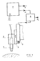
- FIG. 3 gives a schematic representation of a device allowing the implementation of the method.
- the probe 1 is mounted on a support 2 compor as a carriage 3 mobile in translation following a trajectory normal to a part 4 to be checked maintained on a base.
- the devices for prepositioning the part with respect to the probe are not shown in the diagram because they are not part of the invention, they can be manual or automatic with programmed drive means.
- the carriage 3 is driven by a motor 5, for example an electric motor, which receives a control signal from a control system 6 known per se.
- the box of the system 6 comprises a means making it possible to display a reference value H o and an input for a signal H. This system has the function of comparing H to H o and controlling the supply of the motor until the two values become equal.
- the signal H corresponds to one of the components, for example horizontal, of the impedance of the coil, delivered by the control device 7 by eddy currents.
- This device 7 is also a commercial device, its function in particular to power the probe, to analyze the variations in impedance and to deliver two signals H and V representative of its components.
- the invention is not limited to the embodiment shown; it includes all the equivalents within the reach of those skilled in the art.
- the application is not limited to the measurement of thicknesses.
Description
L'invention se rapporte à une méthode et un dispositif pour le contrôle non destructif par Courants de Foucault.The invention relates to a method and a device for non-destructive testing by eddy currents.
On rapelle que le contrôle par Courants de Foucault consiste, par exemple, à alimenter une bobine montée sur une sonde, par un courant périodique de fréquence donnée, à présenter la sonde sur la pièce à contrôler et à analyser les variations d'impédance de la bobine causées par les courants de Foucault induits dans la pièce.It is recalled that the eddy current control consists, for example, in supplying a coil mounted on a probe, by a periodic current of given frequency, in presenting the probe on the part to be checked and in analyzing the variations in impedance of the coil caused by eddy currents induced in the room.
L'impédance est un vecteur à deux composantes l'une résistive, l'autre réactive. Les appareils de contrôle par courants de Foucault utilisant deux axes orthonormés quelconques ne permettent pas en général de connaître les deux axes résistif et réactif. Cependant les appareils courants comprennent un moyen de réglage du déphasage des composantes, il est ainsi possible de déplacer le repère par rotation, ils comprennent également un moyen de réglage par translation. Les composantes obtenues se déduisent donc des composantes résistive et réactive par simple changement de repère. Par la suite il ne sera question que de composante horizontale et de composante verticale de l'impédance.Impedance is a vector with two components, one resistive, the other reactive. The eddy current control devices using any two orthonormal axes do not generally make it possible to know the two resistive and reactive axes. However, current devices include a means of adjusting the phase shift of the components, it is thus possible to move the reference frame by rotation, they also include a means of adjustment by translation. The components obtained are therefore deduced from the resistive and reactive components by simple change of reference. Thereafter, only the horizontal component and the vertical component of the impedance will be discussed.
Quand on visualise sur un oscilloscope la valeur de l'impédance d'une bobine d'une sonde de contrôle du type absolu, cette valeur est représentée par un point. Si on approche la sonde d'une pièce métallique ce point décrit une courbe que nous nommerons par la suite courbe de décollement. Cette courbe s'étend entre deux points extrêmes: un point représentatif de la valeur de l'impédance de la bobine dite « à l'air », c'est-à-dire quand celle-ci est suffisamment éloignée de la pièce pour ne pas subir son influence et un point représentatif de la valeur de l'impédance de la bobine quand la sonde est au contact de la pièce.When viewing the value of the impedance of a coil of an absolute type control probe on an oscilloscope, this value is represented by a point. If we approach the probe of a metallic part this point describes a curve which we will call thereafter detachment curve. This curve extends between two extreme points: a point representative of the value of the impedance of the coil called "air", that is to say when it is sufficiently far from the part to not not undergo its influence and a point representative of the value of the impedance of the coil when the probe is in contact with the workpiece.
Pour des conditions opératoires données la longueur de ce segment de courbe ainsi que sa position autour du point « à l'air vont être fonction de paramètres caractérisant la pièce et la position de la sonde.For given operating conditions, the length of this curve segment as well as its position around the "air" point will depend on parameters characterizing the part and the position of the probe.
Ainsi un entrefer entre la sonde et la pièce dû par exemple à la présence d'un revêtement non conducteur de l'électricité à la surface de la pièce ou bien à une couche d'air agit sur la longueur de la courbe en fonction de son épaisseur.Thus an air gap between the probe and the part due for example to the presence of a coating which does not conduct electricity on the surface of the part or else to a layer of air acts on the length of the curve as a function of its thickness.
D'autres paramètres vont influer sur la position de la courbe; il s'agit par exemple de la perméabilité magnétique, de la conductivité, de la présence de criques ou de défauts dans la matière, de l'épaisseur de la pièce; pour ce dernier paramètre notamment son influence n'est mesurable que s'il est de l'ordre de grandeur de la profondeur de pénétration des courants de Foucault dans la pièce.Other parameters will influence the position of the curve; these are, for example, magnetic permeability, conductivity, the presence of cracks or defects in the material, the thickness of the part; for this latter parameter, in particular, its influence can only be measured if it is of the order of magnitude of the penetration depth of the eddy currents in the room.
L'invention se propose d'utiliser les propriétés de cette courbe et a pour objet une méthode permettant de caractériser les pièces conductrices de l'électricité suivant des paramètres qui ont une influence sur la courbe de décollement. Elle pourra s'appliquer chaque fois que le contrôle est effectué par mesure ponctuelle sur la pièce et pourra être étendue aux méthodes de contrôle où l'on effectue un balayage de la surface de la pièce.The invention proposes to use the properties of this curve and relates to a method for characterizing the electrically conductive parts according to parameters which have an influence on the separation curve. It can be applied each time the control is carried out by spot measurement on the part and can be extended to control methods where a scan of the surface of the part is carried out.
L'invention s'applique donc à:
- - la mesure des épaisseurs de paroi de pièces en particulier pour des pièces creuses telles que les aubes de turbine de turbomachine pourvues de cavités internes pour la circulation de fluide réfrigérant et obtenues par fonderie de précision avec noyau céramique dissous après solidification de la pièce.
- - la mesure des épaisseurs des revêtements conducteurs de l'électricité déposés à la surface des pièces.
- - la mesure de l'espacement entre feuilles conductrices de l'électricité.
- - le tri matière.
- - le contrôle de traitement thermique.
- - la recherche d'hétérogénéités de structure des matériaux.
- - l'évaluation des évolutions structurales occasionnées par le fonctionnement des pièces.
- - la détection de défauts (criques, manques de matière etc.... ).
- - the measurement of the wall thicknesses of parts in particular for hollow parts such as the turbomachine turbine blades provided with internal cavities for the circulation of coolant and obtained by precision foundry with dissolved ceramic core after solidification of the part.
- - the measurement of the thicknesses of the electrically conductive coatings deposited on the surface of the parts.
- - the measurement of the spacing between electrically conductive sheets.
- - material sorting.
- - heat treatment control.
- - the search for heterogeneities in the structure of materials.
- - the evaluation of structural changes caused by the functioning of the parts.
- - detection of faults (cracks, lack of material, etc.).
Cette liste n'étant pas exhaustive.This list is not exhaustive.
Habituellement on réalise ce type de contrôle en amenant simplement la sonde au contact de la pièce et en exploitant la valeur de l'impédance en ce point par comparaison d'une des composantes avec une valeur de référence. Cette technique présente cependant de nombreux inconvénients. Les matériaux constituant la sonde sont fragiles, on constate une usure rapide et une détérioration de la bobine par les chocs répétés sur la pièce. La pression exercée à l'extrémité de la sonde peut entraîner des effets parasites qui faussent les mesures. La sonde chauffée par effet Joule est refroidie par échange thermique avec la pièce qui est à température ambiante, cette variation de température entraîne des effets parasites. Enfin le moindre défaut d'orthogonalité de l'axe de la sonde conduit à un effet d'entrefer agissant également sur l'impédance.Usually this type of control is carried out by simply bringing the probe into contact with the part and by exploiting the value of the impedance at this point by comparing one of the components with a reference value. However, this technique has many drawbacks. The materials constituting the probe are fragile, there is rapid wear and deterioration of the coil by repeated shocks to the part. The pressure exerted at the end of the probe can cause parasitic effects which falsify the measurements. The probe heated by the Joule effect is cooled by heat exchange with the part which is at room temperature, this temperature variation leads to parasitic effects. Finally, the slightest defect in the orthogonality of the probe axis leads to a gap effect also acting on the impedance.
On peut atténuer certains de ces inconvénients en collant un ruban de matière synthétique à l'extrémité de la sonde pour la protéger ou bien en déplaçant la bobine légèrement en retrait dans une gaine ; mais on ne peut éviter alors une dispersion entre les sondes qui se traduit par de légères variations de la distance de la bobine à la pièce faussant les mesures et nécessitant au moins des étalonnages et des corrections délicates.We can mitigate some of these drawbacks by sticking a plastic tape to the end of the probe to protect it or by moving the coil slightly recessed in a sheath; but it is therefore not possible to avoid a dispersion between the probes which results in slight variations in the distance from the coil to the workpiece, distorting the measurements and requiring at least calibrations and delicate corrections.
Le brevet DE 3 324 444 prévoit d'effectuer une mesure par courants de Foucault sans contact entre la pièce et la sonde en utilisant une sonde différentielle à deux bobines qui remplit une double fonction de mesure du décollement d'une part et de contrôle du défaut de la pièce d'autre part.
Ce dispositif permet de connaître à tout moment l'erreur de mesure du défaut due à la variation de décollement et utilise une unité de calcul complexe pour corriger en permanence cette erreur, lors du balayage de la pièce.This device makes it possible to know at any time the error of measurement of the defect due to the variation of delamination and uses a complex calculation unit to permanently correct this error, during the scanning of the part.
La présente invention vise également à effectuer un contrôle sans contact entre la sonde et la pièce, mais en utilisant une sonde de mesure à une seule bobine qui ne nécessite ni moyens de calcul de correction d'erreur ni sonde différentielle à double bobine.The present invention also aims to carry out a control without contact between the probe and the part, but by using a measurement probe with a single coil which requires neither means of calculation of error correction nor differential probe with double coil.
Conformément à l'invention on remédie aux inconvénients précités en positionnant la sonde, au droit du point de mesure sur la pièce à une distance suffisante pour que ladite pièce n'ait aucune influence sur l'impédance de ladite sonde, puis on déplace la sonde en translation vers la pièce jusqu'à une distance de la surface correspondant à une valeur prédéterminée de la composante de l'impédance de la sonde dont l'évolution est la plus influencée par la distance sonde-pièce, notamment la composante de l'axe horizontal, et on effectue la mesure sur l'autre composante.In accordance with the invention, the abovementioned drawbacks are remedied by positioning the probe, in line with the measurement point on the part at a sufficient distance so that said part has no influence on the impedance of said probe, then the probe is moved. in translation towards the workpiece up to a distance from the surface corresponding to a predetermined value of the component of the probe impedance, the evolution of which is most influenced by the probe-workpiece distance, in particular the component of the axis horizontal, and the measurement is made on the other component.
En effet, grâce à cette méthode on élimine tous les facteurs parasites liés au contact de la sonde avec la pièce et on obtient des résultats de grande fiabilité. De plus elle se prête aisément à une automatisation des mesures ce qui est d'un grand intérêt quand on veut réaliser des contrôles de pièces en cours de fabrication.In fact, thanks to this method, all the parasitic factors linked to the contact of the probe with the part are eliminated and results of great reliability are obtained. In addition, it easily lends itself to automation of measurements, which is of great interest when you want to carry out part checks during production.
D'autres caractéristiques et avantages de l'invention sont développés dans la description qui suit où l'on se réfère à la mesure d'épaisseur de pièces en certains points et où :
- La figure 1 représente un faisceau de courbes de décollement pour des pièces de différentes épaisseurs.
- La figure 2 illustre le principe de la méthode selon l'invention.
- La figure 3 donne une représentation schématique de l'appareillage selon l'invention.
- FIG. 1 represents a bundle of detachment curves for parts of different thicknesses.
- FIG. 2 illustrates the principle of the method according to the invention.
- Figure 3 gives a schematic representation of the apparatus according to the invention.
On a représenté à la figure 1 les courbes de décollement obtenues pour des pièces de trois épaisseurs différentes e1, e2, e3, ces courbes convergent au point A qui correspond à la valeur de l'impédance de la bobine en position éloignée des pièces. On a réglé la phase de l'appareil de contrôle pour qu'elles présentent une orientation à peu près parallèle à l'axe horizontal. Quand on approche la sonde de la pièce d'épaisseur e1 on se déplace de A vers C1 qui est la valeur de l'impédance au point de contact ; pour des épaisseurs différentes e1 e2 e3 on obtient les courbes AC1, Ac2 et Ac3.FIG. 1 shows the separation curves obtained for parts of three different thicknesses e 1 , e 2 , e 3 , these curves converge at point A which corresponds to the value of the impedance of the coil in position distant from the rooms. The phase of the recording equipment has been adjusted so that they have an orientation roughly parallel to the horizontal axis. When we approach the probe of the piece of thickness e 1 we move from A to C1 which is the value of the impedance at the point of contact; for different thicknesses e 1 e 2 e 3 we obtain the curves A C1 , Ac 2 and Ac 3 .
En effectuant la mesure lorsque la sonde est au contact de la pièce, pour deux épaisseurs différentes on obtient bien deux valeurs différentes de la composante verticale de l'impédance à partir desquelles on peut déterminer les épaisseurs. Malheureusement si, par exemple pour la pièce e1, la sonde vient à être légèrement inclinée par rapport à la surface on va effectuer le relevé au point C'1 et le résultat de la mesure donnera pour la pièce une épaisseur e2 au lieu de e1.By carrying out the measurement when the probe is in contact with the workpiece, for two different thicknesses, two different values of the vertical component of the impedance are indeed obtained from which the thicknesses can be determined. Unfortunately if, for example for the piece e 1 , the probe comes to be slightly inclined with respect to the surface we will take the reading at point C'1 and the result of the measurement will give for the piece a thickness e 2 instead of e 1 .
Une erreur du même type est possible quand on place la bobine en retrait dans une gaine concentrique à la sonde afin d'éliminer certains effets parasites dûs par exemple à la pression d'appui de la sonde sur la pièce. Quand au cours du contrôle d'un lot de pièces on remplace une première sonde où la bobine est en retrait d'une distance d1 dans sa gaine par une deuxième où la distance est d2, l'entrefer n'est plus le même. Si on ne tient pas compte de cet écart, pour une pièce d'épaisseur e1, la mesure donnera par exemple la valeur correspondant à C'1, soit e2 au lieu de e1.An error of the same type is possible when the coil is placed back in a sheath concentric with the probe in order to eliminate certain parasitic effects due for example to the pressure of support of the probe on the part. When, during the control of a batch of parts, a first probe is replaced where the coil is set back from a distance d1 in its sheath by a second where the distance is d2, the air gap is no longer the same. If this difference is not taken into account, for a piece of thickness e1, the measurement will give for example the value corresponding to C'1, that is e 2 instead of e 1 .
La figure 2 montre le principe de la méthode selon l'invention; elle est illustrée dans une application à la mesure des épaisseurs d'un lot de pièces. En premier lieu on règle la phase de l'appareil de contrôle par courants de Foucault, (cet appareil ne présente en soi rien de particulier), de manière à obtenir sur l'oscilloscope un faisceau de courbes de décollement pour la gamme des épaisseurs concernées, approximativement parallèle à l'un des deux axes. Ce faisceau est représenté en traits interrompus il est orienté selon l'horizontale dans l'exemple choisi. On approche la sonde sensiblement normalement à la surface de la pièce au voisinage du point de mesure à une distance suffisante pour que sur l'écran le point représentatif de l'impédance soit en A. Ceci peut être réalisé en utilisant des moyens supports à mouvements automatiques préprogrammés. La sonde est ensuite entraînée dans un mouvement de translation en direction de la pièce jusqu'à ce que la composante horizontale H atteigne une valeur prédéterminée Ho. Le choix de cette première composante correspond à l'orientation sensiblement horizontale du faisceau. Cette valeur Ho aura été choisie par un essai préalable, afin d'obtenir une valeur significative de la composante verticale pour les pièces concernées par la mesure.Figure 2 shows the principle of the method according to the invention; it is illustrated in an application for measuring the thicknesses of a batch of parts. Firstly, the phase of the eddy current control device is adjusted (this device does not in itself present anything particular), so as to obtain on the oscilloscope a bundle of separation curves for the range of thicknesses concerned. , approximately parallel to one of the two axes. This beam is shown in dashed lines and is oriented horizontally in the example chosen. The probe is approached substantially normally on the surface of the part in the vicinity of the measurement point at a sufficient distance so that on the screen the point representative of the impedance is at A. This can be achieved by using movement support means automatic preprogrammed. The probe is then driven in a translational movement towards the workpiece until the horizontal component H reaches a predetermined value H o . The choice of this first component corresponds to the substantially horizontal orientation of the beam. This value H o will have been chosen by a prior test, in order to obtain a significant value of the vertical component for the parts concerned by the measurement.
Cette valeur sera proche, mais hors, de l'intervalle dans lequel se situe l'ensemble des valeurs correspondant au contact de la sonde avec les pièces à contrôler. Le mouvement est arrêté pour H = Ho; la sonde est prête pour la mesure; il suffit de relever la valeur V de la deuxième composante, verticale, en ce point. A cette valeur correspond une épaisseur que l'on peut déterminer simplement par l'intermédiaire par exemple d'une courbe composante V - épaisseur préalablement établie. La figure 3 donne une représentation schématique d'un dispositif permettant la mise en oeuvre de la méthode.This value will be close to, but out of, the interval in which all the values corresponding to the contact of the probe with the parts to be checked are situated. The movement is stopped for H = H o ; the probe is ready for measurement; it is enough to note the value V of the second component, vertical, at this point. To this value corresponds a thickness which can be determined simply by means of, for example, a component V curve - thickness previously established. FIG. 3 gives a schematic representation of a device allowing the implementation of the method.
La sonde 1 est montée sur un support 2 comportant un chariot 3 mobile en translation suivant une trajectoire normale à une pièce 4 à contrôler maintenue sur un socle. Les dispositifs de prépositionnement de la pièce par rapport à la sonde ne sont pas représentés sur le schéma car ils ne font pas partie de l'invention, ils peuvent être manuels ou automatiques avec des moyens d'entraînement programmés. Le chariot 3 est entraîné par un moteur 5 par exemple électrique, qui reçoit un signal de commande d'un système d'asservissement 6 connu en soi. Le boitier du système 6 comporte un moyen permettant d'afficher une valeur de référence Ho et une entrée pour un signal H. Ce système a pour fonction de comparer H à Ho et de commander l'alimentation du moteur jusqu'à ce que les deux valeurs deviennent égales. Le signal H correspond à l'une des composantes, par exemple horizontale, de l'impédance de la bobine, délivrée par l'appareil 7 de contrôle par courants de Foucault. Cet appareil 7 est lui aussi un appareil du commerce, il a pour fonction notamment d'alimenter la sonde, d'en analyser les variations d'impédance et de délivrer deux signaux H et V représentatifs de ses composantes.The
L'invention ne se limite pas au mode de réalisation représenté; elle englobe tous les équivalents à la portée de l'homme de métier. Par exemple, on peut utiliser un autre système d'asservissement que celui décrit, on peut opérer manuellement; au lieu d'un mouvement continu, on peut déplacer la sonde par incréments, en particulier lorsqu'on utilise un système d'asservissement par ordinateur, jusqu'à obtenir la valeur prédéterminée de Ho. L'application ne se limite pas à la mesure des épaisseurs. Enfin, il est clair que les mesures peuvent être effectuées sur un nombre de points aussi élevé que l'on veut sur la même pièce.The invention is not limited to the embodiment shown; it includes all the equivalents within the reach of those skilled in the art. For example, we can use a different servo system than that described, we can operate manually; instead of a continuous movement, the probe can be moved in increments, in particular when using a computer servo system, until the predetermined value of H o is obtained. The application is not limited to the measurement of thicknesses. Finally, it is clear that the measurements can be made on as many points as you want on the same part.
Claims (3)
Applications Claiming Priority (2)
| Application Number | Priority Date | Filing Date | Title |
|---|---|---|---|
| FR8419409A FR2574938B1 (en) | 1984-12-19 | 1984-12-19 | METHOD OF CONTROLLING BY CONTACTLESS EDGE CURRENT AND DEVICE FOR IMPLEMENTING IT |
| FR8419409 | 1984-12-19 |
Publications (3)
| Publication Number | Publication Date |
|---|---|
| EP0187094A1 EP0187094A1 (en) | 1986-07-09 |
| EP0187094B1 EP0187094B1 (en) | 1988-10-26 |
| EP0187094B2 true EP0187094B2 (en) | 1992-05-13 |
Family
ID=9310756
Family Applications (1)
| Application Number | Title | Priority Date | Filing Date |
|---|---|---|---|
| EP85402524A Expired - Lifetime EP0187094B2 (en) | 1984-12-19 | 1985-12-18 | Contactless eddy current testing method, and apparatus for carrying out this method |
Country Status (4)
| Country | Link |
|---|---|
| US (1) | US4727322A (en) |
| EP (1) | EP0187094B2 (en) |
| DE (1) | DE3565895D1 (en) |
| FR (1) | FR2574938B1 (en) |
Families Citing this family (36)
| Publication number | Priority date | Publication date | Assignee | Title |
|---|---|---|---|---|
| DE3686330T2 (en) * | 1985-12-28 | 1993-02-18 | Yamaha Corp | CONTACTLESS MARKING SENSOR. |
| GB8622702D0 (en) * | 1986-09-20 | 1986-10-29 | Ford Motor Co | Measuring coating thickness |
| US4849693A (en) * | 1988-02-29 | 1989-07-18 | Battelle Memorial Institute | Automated measurement system employing eddy currents to adjust probe position and determine metal hardness |
| US5200704A (en) * | 1991-02-28 | 1993-04-06 | Westinghouse Electric Corp. | System and method including a buried flexible sheet target impregnated with ferromagnetic particles and eddy current probe for determining proximity of a non-conductive underground structure |
| DE69222207T2 (en) * | 1991-03-13 | 1998-03-05 | Westinghouse Electric Corp | Method of determining the amount of deformation in a material in response to a compressive force |
| US5223793A (en) * | 1991-04-29 | 1993-06-29 | Intex Inc. | Apparatus for controlled rotation of a sphere or ball for inspecting or marking the surface with a predetermined pattern |
| US5394084A (en) * | 1991-12-23 | 1995-02-28 | The Boeing Company | Method and apparatus for reducing errors in eddy-current conductivity measurements due to lift-off by interpolating between a plurality of reference conductivity measurements |
| US5420507A (en) * | 1992-09-28 | 1995-05-30 | Edward L. Laskowski | Method and apparatus for sensing a target characteristic by measuring both impedance and resonant frequency of a tank circuit |
| US5552704A (en) * | 1993-06-25 | 1996-09-03 | Tencor Instruments | Eddy current test method and apparatus for measuring conductance by determining intersection of lift-off and selected curves |
| US5541510A (en) * | 1995-04-06 | 1996-07-30 | Kaman Instrumentation Corporation | Multi-Parameter eddy current measuring system with parameter compensation technical field |
| US6285183B1 (en) | 1996-09-30 | 2001-09-04 | Mcdonnell Douglas Corporation | Method and system for measuring the volume loss of a metal substrate |
| DE19860487A1 (en) * | 1998-12-28 | 2000-07-06 | Siemens Ag | Method and device for spatially measuring an inhomogeneity on a surface of a nuclear reactor component and application of the method for measuring an electrically practically non-conductive layer |
| US6346807B1 (en) * | 1999-10-22 | 2002-02-12 | Bently Nevada Corporation | Digital eddy current proximity system: apparatus and method |
| JP3758439B2 (en) * | 1999-12-20 | 2006-03-22 | 日本精工株式会社 | Method for detecting a defect of a test object having a curved surface in a non-contact manner along the curved surface |
| SE520322C2 (en) | 2000-03-23 | 2003-06-24 | Daprox Ab | Method and apparatus for spacing between a stator and a rotating rotor opposed thereto |
| TWI241398B (en) * | 2000-03-28 | 2005-10-11 | Toshiba Corp | Eddy current loss measuring sensor, film thickness measuring device, film thickness measuring method and recording medium |
| US6741076B2 (en) | 2000-04-07 | 2004-05-25 | Cuong Duy Le | Eddy current measuring system for monitoring and controlling a CMP process |
| US6762604B2 (en) | 2000-04-07 | 2004-07-13 | Cuong Duy Le | Standalone eddy current measuring system for thickness estimation of conductive films |
| US6407546B1 (en) * | 2000-04-07 | 2002-06-18 | Cuong Duy Le | Non-contact technique for using an eddy current probe for measuring the thickness of metal layers disposed on semi-conductor wafer products |
| US6549006B2 (en) | 2000-04-07 | 2003-04-15 | Cuong Duy Le | Eddy current measurements of thin-film metal coatings using a selectable calibration standard |
| US20030210041A1 (en) * | 2000-04-07 | 2003-11-13 | Le Cuong Duy | Eddy current measuring system for monitoring and controlling a chemical vapor deposition (CVD) process |
| US6593737B2 (en) | 2000-08-24 | 2003-07-15 | Shell Oil Company | Method for measuring the wall thickness of an electrically conductive object |
| JP2002148012A (en) * | 2000-11-08 | 2002-05-22 | Ulvac Japan Ltd | Apparatus and method for measurement of film thickness |
| US6933718B2 (en) * | 2001-06-12 | 2005-08-23 | The Boeing Company | Quantification method and system for corrosion and damage assessment |
| GB0124910D0 (en) | 2001-10-17 | 2001-12-05 | Accentus Plc | Measurement of material properties |
| AU2002329471A1 (en) * | 2001-10-17 | 2003-04-28 | Aea Technology Plc | Method and apparatus for measuring material properties and lift-off components of an object using a magnetic probe |
| US20040207395A1 (en) * | 2002-04-08 | 2004-10-21 | Moshe Sarfaty | Eddy current-capacitance sensor for conducting film characterization |
| JP4451111B2 (en) * | 2003-10-20 | 2010-04-14 | 株式会社荏原製作所 | Eddy current sensor |
| US7295003B2 (en) * | 2004-09-22 | 2007-11-13 | The Boeing Company | Non-destructive testing system and method utilizing a magnetic field to identify defects in a layer of a laminated material |
| US7830140B2 (en) * | 2007-08-07 | 2010-11-09 | General Electric Company | Eddy current system and method for estimating material properties of parts |
| FI20085456L (en) * | 2008-05-15 | 2009-11-16 | Valtion Teknillinen | Method and apparatus for identifying an electronic code |
| GB0820930D0 (en) * | 2008-11-17 | 2008-12-24 | Dvs Techology Ltd | Coating thickness measurement |
| US20130249540A1 (en) * | 2012-03-22 | 2013-09-26 | Olympus Ndt Inc. | Eddy current array probe and method for lift-off compensation during operation without known lift references |
| US9335151B2 (en) | 2012-10-26 | 2016-05-10 | Applied Materials, Inc. | Film measurement |
| CN106404899A (en) * | 2016-08-29 | 2017-02-15 | 爱德森(厦门)电子有限公司 | Eddy current detection uplift shake compensation method |
| CN116086300B (en) * | 2023-04-07 | 2023-06-09 | 苏州中科科仪技术发展有限公司 | Calibration method of magnetic suspension molecular pump displacement sensor and application thereof |
Family Cites Families (12)
| Publication number | Priority date | Publication date | Assignee | Title |
|---|---|---|---|---|
| US3358225A (en) * | 1964-03-27 | 1967-12-12 | Richard S Peugeot | Lift-off compensation for eddy current testers |
| GB1130870A (en) * | 1966-10-20 | 1968-10-16 | Nat Res Dev | Method and apparatus for detecting and measuring cracks in metal structures |
| US3718855A (en) * | 1970-11-30 | 1973-02-27 | R Cordova | Eddy current flaw detection system |
| JPS5376926A (en) * | 1976-12-21 | 1978-07-07 | Nippon Kokan Kk | Molten metal level monitor controller of continuous casting machine that use eddy flow system range finder for measurement of molten metal level |
| DE2815228C3 (en) * | 1978-04-08 | 1980-11-27 | Institut Dr. Friedrich Foerster Pruefgeraetebau, 7410 Reutlingen | Test arrangement for the non-destructive testing of metallic test material |
| US4215310A (en) * | 1978-07-10 | 1980-07-29 | United States Steel Corporation | Magnetic testing method and apparatus having provision for eliminating inaccuracies caused by gaps between probe and test piece |
| US4438754A (en) * | 1979-08-14 | 1984-03-27 | Shell Oil Company | Method for sensing and remotely controlling a tool to workpiece spatial relationship |
| CA1158314A (en) * | 1980-08-18 | 1983-12-06 | Majesty (Her) In Right Of Canada As Represented By Atomic Energy Of Cana Da Limited | Eddy current surface probe |
| JPS57178155A (en) * | 1981-04-27 | 1982-11-02 | Hitachi Ltd | Eddy current test equipment |
| US4596953A (en) * | 1982-04-14 | 1986-06-24 | Daidotokushuko Kabushikikaisha | Apparatus for scanning a material for detection of flaws and having material axis deviation detection |
| US4641092A (en) * | 1982-07-08 | 1987-02-03 | Sumitomo Metal Industries, Ltd. | Rotary probe apparatus for detecting flaws in a test object |
| US4644274A (en) * | 1983-04-01 | 1987-02-17 | General Electric Company | Apparatus for supporting an eddy current probe used to scan an irregular surface |
-
1984
- 1984-12-19 FR FR8419409A patent/FR2574938B1/en not_active Expired
-
1985
- 1985-12-17 US US06/809,785 patent/US4727322A/en not_active Expired - Lifetime
- 1985-12-18 EP EP85402524A patent/EP0187094B2/en not_active Expired - Lifetime
- 1985-12-18 DE DE8585402524T patent/DE3565895D1/en not_active Expired
Also Published As
| Publication number | Publication date |
|---|---|
| FR2574938B1 (en) | 1986-12-26 |
| EP0187094A1 (en) | 1986-07-09 |
| EP0187094B1 (en) | 1988-10-26 |
| US4727322A (en) | 1988-02-23 |
| DE3565895D1 (en) | 1988-12-01 |
| FR2574938A1 (en) | 1986-06-20 |
Similar Documents
| Publication | Publication Date | Title |
|---|---|---|
| EP0187094B2 (en) | Contactless eddy current testing method, and apparatus for carrying out this method | |
| EP2368125B1 (en) | Apparatus for regulating a wire anemometer | |
| EP1850088B1 (en) | Wall thickness measurement, in particular of a vane, by eddy currents | |
| FR2602053A1 (en) | DEVICE AND METHOD FOR NON-DESTRUCTIVE TESTING OF A WORKPIECE BY MEASURING THE IMPEDANCE OF CURRENT FOUCAULT | |
| US20110249115A1 (en) | Apparatus for crack detection during heat and load testing | |
| FR2854954A1 (en) | HIGH CAPACITY ABSOLUTE DEFECT IMAGING | |
| EP0146091B1 (en) | Method and system for non-destructive eddy current testing using a frequency sweep | |
| FR2548351A1 (en) | METHOD AND APPARATUS FOR NON-CONTACT MEASUREMENT OF A SOLIDIFIED SHELL OF A CAST-METALLIC PIECE | |
| EP0290513B1 (en) | Method for detecting thickness variations in the wall of a current conducting tubular body | |
| Zenzinger et al. | Crack detection using eddytherm | |
| FR2594532A1 (en) | SIGNAL PROCESSING METHOD AND FAULTY CURRENT FAULT DETECTOR FOR ELECTROMAGNETIC INDUCTION TEST | |
| JP2008537781A5 (en) | ||
| EP0021893A1 (en) | Method and apparatus for eddy current testing of metallic products and application of the method and apparatus | |
| FR2487969A1 (en) | FOUCAULT CURRENT SENSOR FOR NON-DESTRUCTIVE TESTING DEVICES FOR BONES AND TUBES AND METHOD OF MANUFACTURING THE SAME | |
| JPH05149927A (en) | Method and apparatus for inspecting conductor film | |
| EP0061956B1 (en) | Method for eddy current non destructive testing with lift off correction and apparatus for using this method | |
| EP0736173B1 (en) | Method and device for magnetic testing of metal products | |
| EP1167917A1 (en) | Method for wall thickness measurement of a hollow blade | |
| FR2531537A1 (en) | METHOD AND APPARATUS FOR DETECTING FAULTY CURRENT FAULTS | |
| FR2689637A1 (en) | Non-destructive testing by scanning surface with eddy current probe | |
| EP2368126B1 (en) | Anemometer probe and method of production | |
| WO2019122672A1 (en) | Method for characterizing and monitoring the homogeneity of metal parts manufactured by laser sintering | |
| FR2675263A1 (en) | METHOD AND DEVICE FOR NON-DESTRUCTIVE ULTRASONIC INSPECTION OF PARTS OF REFRACTORY MATERIAL. | |
| EP1998172B1 (en) | Marking of points of interest on the surface of a workpiece and application to optimising the trajectory and angulation of eddy current probes | |
| JPH0480604A (en) | Scanning tunneling microscope and through-hole plating inspection device including same |
Legal Events
| Date | Code | Title | Description |
|---|---|---|---|
| PUAI | Public reference made under article 153(3) epc to a published international application that has entered the european phase |
Free format text: ORIGINAL CODE: 0009012 |
|
| 17P | Request for examination filed |
Effective date: 19860116 |
|
| AK | Designated contracting states |
Kind code of ref document: A1 Designated state(s): BE CH DE FR GB IT LI NL SE |
|
| 17Q | First examination report despatched |
Effective date: 19880330 |
|
| ITF | It: translation for a ep patent filed |
Owner name: BARZANO' E ZANARDO MILANO S.P.A. |
|
| GRAA | (expected) grant |
Free format text: ORIGINAL CODE: 0009210 |
|
| AK | Designated contracting states |
Kind code of ref document: B1 Designated state(s): BE CH DE FR GB IT LI NL SE |
|
| GBT | Gb: translation of ep patent filed (gb section 77(6)(a)/1977) | ||
| REF | Corresponds to: |
Ref document number: 3565895 Country of ref document: DE Date of ref document: 19881201 |
|
| PLBI | Opposition filed |
Free format text: ORIGINAL CODE: 0009260 |
|
| 26 | Opposition filed |
Opponent name: ASEA BROWN BOVERI AB Effective date: 19890718 |
|
| NLR1 | Nl: opposition has been filed with the epo |
Opponent name: ASEA BROWN BOVERI AB |
|
| ITTA | It: last paid annual fee | ||
| PUAH | Patent maintained in amended form |
Free format text: ORIGINAL CODE: 0009272 |
|
| STAA | Information on the status of an ep patent application or granted ep patent |
Free format text: STATUS: PATENT MAINTAINED AS AMENDED |
|
| 27A | Patent maintained in amended form |
Effective date: 19920513 |
|
| AK | Designated contracting states |
Kind code of ref document: B2 Designated state(s): BE CH DE FR GB IT LI NL SE |
|
| REG | Reference to a national code |
Ref country code: CH Ref legal event code: AEN |
|
| ITF | It: translation for a ep patent filed |
Owner name: BARZANO' E ZANARDO MILANO S.P.A. |
|
| NLR3 | Nl: receipt of modified translations in the netherlands language after an opposition procedure | ||
| NLR2 | Nl: decision of opposition | ||
| REG | Reference to a national code |
Ref country code: GB Ref legal event code: 777B |
|
| GBTA | Gb: translation of amended ep patent filed (gb section 77(6)(b)/1977) |
Effective date: 19930316 |
|
| EAL | Se: european patent in force in sweden |
Ref document number: 85402524.4 |
|
| REG | Reference to a national code |
Ref country code: GB Ref legal event code: IF02 |
|
| REG | Reference to a national code |
Ref country code: FR Ref legal event code: TP Ref country code: FR Ref legal event code: CD |
|
| PGFP | Annual fee paid to national office [announced via postgrant information from national office to epo] |
Ref country code: SE Payment date: 20031125 Year of fee payment: 19 Ref country code: CH Payment date: 20031125 Year of fee payment: 19 |
|
| PGFP | Annual fee paid to national office [announced via postgrant information from national office to epo] |
Ref country code: NL Payment date: 20031126 Year of fee payment: 19 |
|
| PGFP | Annual fee paid to national office [announced via postgrant information from national office to epo] |
Ref country code: GB Payment date: 20031127 Year of fee payment: 19 Ref country code: FR Payment date: 20031127 Year of fee payment: 19 |
|
| PGFP | Annual fee paid to national office [announced via postgrant information from national office to epo] |
Ref country code: BE Payment date: 20031128 Year of fee payment: 19 |
|
| PGFP | Annual fee paid to national office [announced via postgrant information from national office to epo] |
Ref country code: DE Payment date: 20031210 Year of fee payment: 19 |
|
| PG25 | Lapsed in a contracting state [announced via postgrant information from national office to epo] |
Ref country code: GB Free format text: LAPSE BECAUSE OF NON-PAYMENT OF DUE FEES Effective date: 20041218 |
|
| PG25 | Lapsed in a contracting state [announced via postgrant information from national office to epo] |
Ref country code: SE Free format text: LAPSE BECAUSE OF NON-PAYMENT OF DUE FEES Effective date: 20041219 |
|
| PG25 | Lapsed in a contracting state [announced via postgrant information from national office to epo] |
Ref country code: LI Free format text: LAPSE BECAUSE OF NON-PAYMENT OF DUE FEES Effective date: 20041231 Ref country code: CH Free format text: LAPSE BECAUSE OF NON-PAYMENT OF DUE FEES Effective date: 20041231 Ref country code: BE Free format text: LAPSE BECAUSE OF NON-PAYMENT OF DUE FEES Effective date: 20041231 |
|
| BERE | Be: lapsed |
Owner name: SOC. NATIONALE D'ETUDE ET DE CONSTRUCTION DE MOTEU Effective date: 20041231 |
|
| PG25 | Lapsed in a contracting state [announced via postgrant information from national office to epo] |
Ref country code: NL Free format text: LAPSE BECAUSE OF NON-PAYMENT OF DUE FEES Effective date: 20050701 Ref country code: DE Free format text: LAPSE BECAUSE OF NON-PAYMENT OF DUE FEES Effective date: 20050701 |
|
| EUG | Se: european patent has lapsed | ||
| GBPC | Gb: european patent ceased through non-payment of renewal fee |
Effective date: 20041218 |
|
| REG | Reference to a national code |
Ref country code: CH Ref legal event code: PL |
|
| PG25 | Lapsed in a contracting state [announced via postgrant information from national office to epo] |
Ref country code: FR Free format text: LAPSE BECAUSE OF NON-PAYMENT OF DUE FEES Effective date: 20050831 |
|
| NLV4 | Nl: lapsed or anulled due to non-payment of the annual fee |
Effective date: 20050701 |
|
| REG | Reference to a national code |
Ref country code: FR Ref legal event code: ST |
|
| BERE | Be: lapsed |
Owner name: SOC. NATIONALE D'ETUDE ET DE CONSTRUCTION DE MOTEU Effective date: 20041231 |