EP2368126B1 - Anemometer probe and method of production - Google Patents
Anemometer probe and method of production Download PDFInfo
- Publication number
- EP2368126B1 EP2368126B1 EP09795772.4A EP09795772A EP2368126B1 EP 2368126 B1 EP2368126 B1 EP 2368126B1 EP 09795772 A EP09795772 A EP 09795772A EP 2368126 B1 EP2368126 B1 EP 2368126B1
- Authority
- EP
- European Patent Office
- Prior art keywords
- wire
- probe
- pins
- wires
- pin
- Prior art date
- Legal status (The legal status is an assumption and is not a legal conclusion. Google has not performed a legal analysis and makes no representation as to the accuracy of the status listed.)
- Not-in-force
Links
Images


Classifications
-
- G—PHYSICS
- G01—MEASURING; TESTING
- G01P—MEASURING LINEAR OR ANGULAR SPEED, ACCELERATION, DECELERATION, OR SHOCK; INDICATING PRESENCE, ABSENCE, OR DIRECTION, OF MOVEMENT
- G01P5/00—Measuring speed of fluids, e.g. of air stream; Measuring speed of bodies relative to fluids, e.g. of ship, of aircraft
- G01P5/10—Measuring speed of fluids, e.g. of air stream; Measuring speed of bodies relative to fluids, e.g. of ship, of aircraft by measuring thermal variables
- G01P5/12—Measuring speed of fluids, e.g. of air stream; Measuring speed of bodies relative to fluids, e.g. of ship, of aircraft by measuring thermal variables using variation of resistance of a heated conductor
Definitions
- the invention relates to the field of probes for performing near-wall anemometric measurements.
- It relates more particularly to probes or devices of the type anemometer hot wire or cold wire.
- It also relates to a method of manufacturing such a probe.
- It also relates to a device for regulating the supply and the measurement of such a probe.
- the measurements made in the vicinity of a wall are very particular because the wall influences the speed measurement by its presence. This results in an overestimation of the speed value.
- a known probe described in the paper by Ligrani and Bradshaw, 1987, and illustrated on the figure 1 comprises a wire 200 (0.625 ⁇ m diameter hot wire) made of a platinum alloy with 10% rhodium. This wire is traversed by an electric current in its active portion 600 (heated length) and has a shape "U".
- This wire is fixed at the end of two points 400, 600 held together by an araldite adhesive 450.
- the attachment is obtained by two solders (tin) 220 of the wire on the tips.
- the spacing e between the ends of the two pins is of the order of 0.5 mm.
- the wire defines a plane which is inclined at an angle ⁇ of about 15 ° with respect to the plane defined by the points 400, 600.
- the blocking effect is a disturbance on the flow, caused by the excessive proximity of the ends of the pins. This disturbance affects any measurement made at the active part 600.
- a problem is therefore to be able to make a probe that improves the performance of such a probe.
- a probe of the type of that of the figure 1 presents problems of vibration resistance and sensitivity.
- Another aspect of the type of measures envisaged is the filtering effect. This effect occurs when the active area is too large, providing an averaged or integrated measurement, and not a one-off measure.
- the known probes including commercial anemometer assemblies (typically 2.5 ⁇ m diameter probe associated with a constant temperature anemometer), are therefore largely insufficient for the measurement of small scales of turbulence, and totally unsuitable for measurements in close proximity. wall like the ones we want to make.
- multi-wire probes are needed whose volume defined by the set of wires is very small.
- One of the problems posed by the invention is, in particular, to find a production method which makes it possible, in a reproducible manner, to obtain a probe exhibiting excellent performance.
- the invention makes it possible to produce a probe comprising wires of very small diameter, associated with a large spacing between pins, in particular in order to limit the locking effect.
- the invention makes it possible, in particular, to reproducibly produce probes using wires of 0.35 ⁇ m to 0.625 ⁇ m in diameter, for example 0.5 ⁇ m in diameter.
- the ends of the pins can be spaced apart by a distance of at least 4 mm.
- the wire comprises a central core of a platinum-rhodium alloy, with a diameter d of between 0.35 and 0.6 ⁇ m, and a silver sheath, eliminated on a portion of wire, called a sensitive zone, of length between 0.4 mm and 0.5 mm.
- the wire can be soldered to the pins using a tin-lead type solder.
- a probe according to the invention may comprise n parallel wires, n ⁇ 2.
- n may comprise 2 or 3 or 4 wires parallel to each other.
- Step b) preferably comprises the formation of a curvature of the wire.
- a wire resistance measurement can be made to determine the etched length.
- the etching can be carried out using a loop formed by a wire on which a drop of pickling liquid can be maintained.
- an annealing step at a temperature substantially greater than the temperature at which the yarn is intended to be used may be provided.
- brazing it can be performed by hot air gun, or by laser impact.
- step a Before step a), a preliminary step of straightening the wire can be provided.
- a step of mechanically tensioning the yarn less than a few grams, for example 6g or 5g or 4g, may be provided.
- the invention also relates to a method for measuring anemometric quantities, in particular in the vicinity of a wall, comprising the implementation of a probe according to the invention.
- This regulating device can be applied to a probe according to the invention, described above, or to another type of airspeed sensor. But particularly interesting results are obtained with a probe according to the invention.
- the wire and the reference resistor are for example mounted in current mirror.
- the means for regulating a supply current preferably comprise a diode-mounted control transistor and a potentiometer.
- the invention also relates to a method for measuring a temperature in a fluid in flow, comprising the implementation of a thermo-anemometer as above, without additional thermocouple.
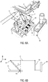
- the probe comprises a wire 2 stretched between the tapered ends of two metal pins 4, 6, which extend in an insulating body 10 of cylindrical shape, preferably a ceramic.
- the probe body 10 consists of a diameter ceramic cylinder which may for example be between 2 and 4 mm, in which are implanted as pins 4, 6 stainless steel needles of diameter for example between 0.2 mm and 0.4 mm.
- the wire 2 is positioned on portions of the pins which are flattened, as seen on the Figure 2C which represents the shape of a pin in side view, before (broken lines) then after (solid lines) thinning.
- the reference 43 designates the flattened portion of the pin 4 shown, on which one end of the wire 2 will be brazed.
- the other pin 6 has the same end structure.
- the end structures are obtained by simultaneous thinning of both ends on a grinding marble.
- the two planar zones thus defined form a single plane. This positioning contributes to excellent wire alignment.
- Each pin therefore has a body 4 1 of substantially cylindrical section, the cylinder being truncated at the end by a plane 43 which intersects a direction AA 'along which the pin extends substantially.
- the axis AA ' is an axis of symmetry of revolution in the case of a cylindrical pin ( Figure 2C ).
- the wire 2 also has an extremely precise alignment, of the order of a hundredth of a millimeter. Unlike the known probe structure (as explained above in connection with the figure 1 ), a straight portion of the wire 2 is positioned on the pins 4, 6. There is no need, as in the case of the figure 1 , bending the wire in the form of a "U", such a curvature affecting the accuracy and reproducibility of the device.
- the solder of the wire 2 on the pins 4, 6 is a tin-lead alloy solder.
- the emergent length L of the pins is approximately of the order of 15 mm, and the distance D which separates them is substantially equal to or greater than 5 mm, and preferably between 5 mm and 8 mm, for flows of boundary layer to vein velocities less than or slightly greater than 12 m / s.
- good behavior is obtained only when the spacing between the pins does not exceed 4 mm. Beyond 4 mm, due to insufficient stiffness of the silver sheath of the wire 2 (whose structure is described below), the shear excitation induces large amplitude oscillations at the wire scale, oscillations that lead to the rupture of the latter.
- the probe body is sheathed with a tube 12 of elastomer, which will absorb the waves or the vibrations being able to propagate towards the wire 2, very fragile.
- the wire 2 is in fact a wire comprising a central part 20 made of platinum or a platinum-rhodium alloy, surrounded by a sheath 22 made of silver, which may have a diameter of between 30 ⁇ m and 80 ⁇ m, as illustrated in FIG. 2D figure .
- the diameter of the central portion 20 is very small, less than 0.635 ⁇ m or 0.6 ⁇ m, for example 0.35 ⁇ m or 0.5 ⁇ m.
- the wire used is preferably a "Wollaston wire” type wire made of a platinum-rhodium alloy (Pt-10% Rh). It is impossible to directly handle a wire of this diameter without risk.
- the silver sheath, with a diameter of 30 ⁇ m to 80 ⁇ m, which surrounds the wire ( 2D Figure ) allows this manipulation.
- Such a yarn offers measurement punctuality greater than that obtained in known devices, since it is possible to define a measurement zone 14 by locally eliminating the sheath of the yarn, as illustrated in FIG. figure 2E .
- a weaker active length would be detrimental to the measurement because the edge effects due to the ends 22 ', 22 "of the sheath at the limits of the measurement zone 14 would then be too great.
- figure 2E where the active part 14 and the silver sheath 22 are clearly visible.
- the active part 14 is not visible on the Figure 2A because the width of this active part (between 0.4 mm and 0.5 mm) is small compared to the distance E between the ends of the pins 4, 6 (at least 5 mm).
- the ratio l / d, of the active length of the wire to its diameter, is substantially between 600 and 1500 (600 ⁇ l / d ⁇ 1500). Beyond this, the punctuality of the measurement disappears: we then find the effects of filtering or averaged measurement already mentioned. With a ratio between 600 and 1500, the hypothesis of the two-dimensionality, therefore of a very flat temperature profile in the active zone, is satisfied. For a ratio less than 600, the appearance of end effects means that the temperature profile along the wire can no longer be likened to a "gate" profile (ie a constant temperature along the wire) this profile is closer to a parabolic profile. Concretely, this situation results in a loss of sensitivity of the wire and a deterioration of the signal-to-noise ratio. Physically, this means that we can not capture phenomena of low amplitude.
- the wire 2 is connected to the pins 4, 6 by brazing the silver sheath 22 on these pins.
- a probe according to the invention has properties of location of the measurement, without filtering effect (due to punctuality on the measurement reached by the very small width of the measuring zone 14), without blocking effect (due to the distance between the ends of the pins). This probe is also resistant to vibrations. A probe according to the invention therefore makes it possible to measure physical quantities as close as possible to a wall, without bias, and therefore without a correction being necessary. For a speed range of less than 10m / s one can approach up to y + ⁇ 2 without wall correction. y + is defined as the product of the velocity of friction by the distance to the wall divided by the kinematic viscosity.
- the invention does not only concern a single-wire probe but also a multi-wire probe.
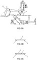
- a double probe for example which associates a hot wire 2 and a parallel cold wire 2 ', with a spacing between the two wires of the order of 0.3 mm, is also an object of the present invention and is shown in a side view. , in figure 3A (We only see the threads from the side, so each thread 2, 2 'is likened to a point in this figure as well as on the figure 3B ).
- the other references are those of Figures 2A-2E and designate the same elements.
- two pairs of pins are provided, the pair 4, 6 already described above, on which is brazed the wire 2, and another pair 4 ', 6' (of which only the pin 4 'is visible on the figure 3A ) on which is brazed the wire 2 '.
- a triple probe which associates three son 2, 2 ', 2 "parallel, is represented, in side view, in figure 3B .
- the references are those of Figures 2A-2E and designate the same elements.
- three pairs of pins are provided, the pair 4, 6 already described above, on which is brazed the wire 2, and another pair 4 ', 6' (only pin 4 'is visible on the figure 3B ) on which is brazed the wire 2 ', a third pair 4 ", 6" (only pin 4 "is visible on the figure 3B ) on which the wire 2 "is soldered in.
- Such a triple probe preferably operates with a hot wire, in the center (the wire 2 ') and two cold wires, on both sides (the wires 2 and 2"), which give information on the direction of the flow.
- At least one of the wires, or each of the wires has the characteristics indicated above, and is fixed in the manner indicated above, on a pair of pins having flattened end portions, which may have been prepared as already explained.
- the wires are separated by a distance ⁇ (maximum distance between two wires) less than or equal to 0.8 mm, or between 0.2 mm and 1 mm or between 0.3 mm and 0.8 mm. More generally, this maximum gap between the planes in which the wires are located, or this maximum spacing between the wires, contributes to the possibility of making spot measurements, making it possible to have an extremely fine representation of the phenomena observed.
- a method of manufacturing a probe according to the invention will now be described. It relates to the realization of a single-wire probe, and can be applied to the realization of a probe to any number of parallel son unless otherwise specified.
- All operations are preferably performed under a binocular loupe, given the size of the elements and the required accuracy.
- This magnifying glass, or any other viewing means chosen or equivalent, allows viewing with a precision of 1/100 th of mm.
- the pins 4, 6 are secured to the probe body 10, 12. In the latter, holes were made or grooves were dug to precisely position these pins.
- the pins are inserted into the probe body using a template so that they protrude from the probe body of equal length.
- soldered connection between the electric supply cables 19, 19 '( Figure 2A ) (it is through these connection means that the current that must pass in the wire 2) and the pins 4, 6 can be located in the groove or holes of the body 10 or outside. The welding of this connection is performed during this preparation step.
- the sealing of the pins in the support can be provided by coating a concrete whose grip is compatible with the ceramic.
- Tests show that an adhesive, for example Araldite type can also very well provide this sealing function, while retaining some elasticity that is interesting for vibration absorption and saving the probe.
- the probe body 10, once provided with its pins 4, 6, is inserted into an elastomer damping sheath 12, in order to limit the vibrations that can break the active part of the wire, which is very thin.
- the end of the pins 4, 6 is also prepared to ensure that a good contact surface is obtained.
- a slight abrasion of the end of the pins is carried out using fine sandpaper, which can be arranged on a grinding marble, to create a flat 43 at their end, as illustrated in FIG. Figure 2C for pin 4.
- fine sandpaper which can be arranged on a grinding marble
- the probe is placed on the manufacturing support.
- the pins 4, 6 are cleaned to guarantee optimal wettability.
- the ends of the pins are tinned using a solder paste 29 (reference: Castolin 157A) deposited on a stainless steel sheet. using a soldering iron 3, as illustrated in figure 4 .
- the pins are then cleaned with acetone.
- the figure 5 represents the probe body 10, 12, with its pins 4, 6 ready to receive the wire 2 of the probe.
- the body of the probe is mounted on a set of micrometer tables, not visible in the figure, which will make it possible to achieve highly accurate movements in two or three dimensions, to the hundredth of a millimeter.
- the wire used is generally in the form of coils a few centimeters in diameter. This type of wrapped packaging causes a shaping of the wire, all the more important and persistent that the wire is small diameter. It is therefore preferable to roll the wire manually on a flat support to minimize the curvature that results from the memory effect of the metal that has remained wound.
- a support which will allow to braze the wire on the pins 4, 6, comprises a fixed vertical arm 49, and a second arm 51, substantially of the same size and mounted on a pivot connection 53 which allows it to tilt in a vertical plane perpendicular to the axis of the pivot.
- This support is provided with two micrometric tables 69, 71 for controlling the positioning of each arm, and therefore the alignment of the wire 2 and its voltage. Each table will enable extremely precise movements, in one, two or three dimensions, to the nearest hundredth of a millimeter.
- the end of the arms 49, 51 is prelaminated beforehand in order to be able to braze the wire 2. Then the two arms 49, 51 of the support are separated by about twenty millimeters. The wire on both arms is bristled using conventional tin solder, making sure that leave the moving arm vertical.
- the movable arm 51 In order to control the tension on the wire 2, the movable arm 51 is positioned so that it makes an angle ⁇ of 45 ° with the normal. The weight of this arm 51 is adjusted so that, in this position, the tension on the thread is about 4 g. This value was chosen after many attempts to obtain a thread 2, just stretched in a reproducible manner. Then the arm 49 is lowered with the vertical micrometer table 69 so that the two arms are at the same level and the wire is as much as possible horizontally.
- the wire 2 and a first pin are degreased with acetone. This is deposited at the junction between the wire 2 and the first pin a very small solder point with the end of a needle.
- This solder which we will see later that it is lead-based, consists of microbeads 15 ⁇ m in diameter, in different elements (Sn: 62%, Pb: 36%, Ag 2%) combined to obtain a point low melting.
- solder is then melted, for example with the aid of a hot air iron 81 ( Figure 8 ).
- wire 2 is secured to the pin 4, and it is then soldered to its second pin 6.
- the rod 91 When the brazing is performed, the rod 91 is removed, and the pin 6 returns to its initial position relative to the other pin 4.
- the wire 2 then adopts a slight curvature, or arrow, of the order of a few hundredths. mm, for example less than 2/100 th of mm or 4/100 th of mm, in a plane substantially perpendicular to the axis of the body 10 of the probe.
- This curvature will have no influence on the anemometric measurements made thereafter and gives the yarn flexibility to absorb mechanical stresses or vibrations.
- the curvature obtained has no influence on the condition alignment already presented above because it is very weak.
- the Figure 9B represents the two ends of the two pins 4, 6 in position spaced apart from each other using the tool 91 (not shown in this figure). The wire then rests on the two pins, it is already brazed on the pin 6 but not yet brazed on the pin 4.
- the Figure 9C represents the two ends of the two pins 4, 6 and the wire 2 after completion of the second solder and removal of the tool 91.
- the two ends of the two pins 4, 6 have returned to their equilibrium positions.
- the wire is brazed, but has undergone a slight curvature, which is exaggeratedly represented on the Figure 9C .
- Two positions 2, 2 1 of the wire are shown in this figure, respectively with the curvature turned downwards and upwards of the figure.
- the yarn 2 is then cut with a razor blade flush with the pins so that the wire holder assembly can be removed and the remaining wire ends can be removed from the wire holder assembly.
- This wire-arm stripping operation is performed after cutting the wire. Indeed, the latter is very conducive to heat, and, if we point the iron on one of the arms 49, 51 of the wire support, the conduction can soften the solder pin 4, 6 - wire 2 located at a few millimeters, absorb the tension and the curvature or curvature, given to the thread as explained above, and thus seriously compromise the success of the realization of the probe.
- the wire is thus mounted between the pins, it can expose the active part that will be used for measurement.
- This sheath is attacked with nitric acid.
- the length l to be stripped is determined according to the diameter d of the wire knowing that, if one wants to ensure a temperature profile as uniform as possible on the wire during its use in hot wire, a ratio l / d greater than 250 allows to limit the impact on the measurement of the conduction at the ends of the active part (for a given material and therefore a given cold length).
- R ⁇ l S
- a probe with an l / d ratio greater than 1500 does not have the point character required for the measurement: the averaged filtering or averaging effects already mentioned are then found.
- the system used here is composed of a thread 101 ( figure 10 ) a few hundredths of a millimeter in stainless steel.
- the end of this wire forms a loop which allows the retention of the drop 102.
- the latter consisting of pure nitric acid, is deposited on the loop using a syringe. Then approach the loop and the drop using micromanipulators to bring the latter into contact with the wire 2 to strip.
- a back and forth motion is made to dissolve the silver of the sheath 22. Once the drop is saturated with silver, it is removed from the wire and replaced by another drop of silver. 'nitric acid. The procedure is the same until the platinum-rhodium wire 20 appears and the resistance of this wire begins to evolve.
- the etched length is adjusted according to the resistance of the probe. Typically, there is a resistance of 500 ⁇ for wire 0.5 ⁇ m in diameter and 1 k ⁇ for 0.35 ⁇ m wire, which corresponds to a stripped length of 5 to 6 tenths of a millimeter, corresponding to a ratio l / d of the order of 1100 and 1600 respectively.
- a simple electrical circuit consisting of a battery, a potentiometer and a switch is connected to the metal loop carrying the drop and to the two connection wires 19, 19 '(FIG. Figure 2A ) related to the two pins 4, 6 (to avoid any asymmetry of the behavior of the drop).
- a drop 102 is formed for etching, but this time consisting of nitric acid diluted to 5%. It is approached in the same way as the previous drops, so that the yarn is wetted inside the drop.
- the switch is then actuated, briefly because degassing is very fast and violent at the wire scale. After this operation the wire is rinsed with a drop of demineralized water so as to eliminate any residual trace of acid on the wire.
- the probe can then be annealed: the wire 2 is passed through a current calculated as a function of the resistance of the probe.
- the wire is thus brought to a temperature substantially greater than the temperature at which it is intended to work.
- the active part 14 of a sensor according to the invention consists mainly of the wire 2, of very small diameter, of the order of a few tenths of a ⁇ m ( figure 2E ). This wire has no, or little, mechanical strength.
- a misalignment is less than the curvature or curve given to the wire.
- the misalignment must be of the order of the hundredth of a mm, so that the curve keeps a damping function .
- This yarn is generally packaged in a form wrapped around a coil several cm in diameter. It turns out that a voltage of a few grams, for example about 4 g, on the unwound wire is sufficient to lose the memory of its winding. This value allows the production of probes using a wire 2 whose active portion 14 has a diameter of 0.625 microns. On the other hand, for the smaller diameters (0.5 and 0.35 ⁇ m), this voltage is insufficient to obtain alignment conditions which make it possible that there is no breaking of the wire after pickling. A 0.625 ⁇ m diameter wire has a mechanical strength that allows some misalignment that can not be supported by the 0.5 and 0.35 ⁇ m wires.
- the tension has, at first, been increased to bring it up to a value of 7 g.
- This solution has not given satisfactory results insofar as the excess of tension on the wire 2 masks the existence, when it is put in place, of a possible misalignment between the pins 4, 6 and wire 2 itself. This defect may result in stripping, by the breaking of the active portion 14, detectable only after the stroke. To counter the phenomenon of masking of this possible misalignment, it was necessary to return to a voltage of less than 7 g, about 4 g in this case.
- the thread is first straightened, for example by rolling it between a glass plate and a metal block, the surface state of which is polished (standard gauge). This solution brings good results.
- the misalignment tolerated is of the order of a hundredth of a millimeter for a distance between pins of 8 mm.
- the mechanical tension on the wire tested is preferably less than a few grams, around 4 g.
- solder has solved this problem.
- Such solder has a much better mechanical strength and allows manual cutting of the wire by razor blade, much easier to implement, especially in the case of the multi-wire probe.
- the solder is preferably made with a hot air gun 81 ( figure 8 ), which allows remote soldering without contact, thanks in particular to an air jet which carries the energy necessary for the melting of the solder paste. Nevertheless difficulties arise, related to the fact that the jet can not be of specific size.
- a grinding step and a mechanical tension on the wire a few grams, (about 4 g) can solve this problem.
- the second cause is related to a phenomenon of thermal expansion, which could be highlighted in a systematic way only when the wire was prepared with a mechanical tension.
- the active part 14 of the wire was always more or less aligned with the two sections of sheaths 22, but at the break appeared a gap between the two parts of the broken wire. This gap was the signature of the existence of a phenomenon of thermal expansion.
- thermomechanical tension in the wire exists only because the solidification constant of the solder is lower than the constant of cooling of the wire. Added to this is the high diffusivity value of silver, which means that the heated length can reach a few millimeters during the liquefaction time of the solder. Based on a simplified modeling of the length heated on the wire, the temperature difference experienced by the wire and the duration of exposure to the hot source, the estimate of the shortening of the wire after solidification of the solder is of the order of 10 microns. To neutralize this phenomenon of thermomechanical tension, which certainly signifies the breaking of the active part 14 of the wire, the size of the hot air iron nozzle 81 was initially reduced, thinking that this solution would contribute to a decrease in the heating of the wire.
- Another technique uses a very localized power supply by laser beam, whose punctuality has the advantage of not polluting the environment thermally.
- the laser used is pulse mode, YAG type with a maximum power of 30W.
- the frequency and duration of the pulses are adjustable.
- the optimal solution for protecting the wire consisted in inserting the ceramic probe body, once provided with its pins, into a damping sheath 12 of very low hardness (of the order of 25 A shores).
- a probe according to the invention is used with current supply means, and means for measuring variations in electrical resistance of the wire or wires. These are these variations which translate the variations of speed and / or temperature of a fluid carried by a flow in which the probe is immersed.
- the system is decoupled from the electrical network, whose potentials can fluctuate (for example, by starting or stopping neighboring installations).
- the currents and / or the voltages that occur at the sensor are very small and can be easily disturbed by these network fluctuations, however small.
- This solution also makes it possible to supply all the circuits, which thus have a fixed and not fluctuating ground potential, as can be the case when they are connected to electronic voltage regulators.
- the circuits are preferably placed in a box, for example copper, which constitutes a ground plane, connected to the ground of the battery. At this ground plane is also connected a braid surrounding the connection wires of the probe. Thus all protections of this type vis-à-vis electromagnetic fields are connected to a fixed potential.
- a box for example copper, which constitutes a ground plane, connected to the ground of the battery.
- a braid surrounding the connection wires of the probe.
- a particular operation is the so-called "cold wire” operation. This is a constant current mode of operation, in which the current with which the wire is fed is very low.
- the power supply has a large resistance R placed in series with the wire in order to maintain a constant current I w in this wire when the flow velocity varies.
- the wire is integrated with a Wheatstone bridge to accurately measure its Rw resistance ; the output signal is collected at the top of the bridge.
- the constant current anemometer has advantages. We have the choice of overheating, which is very appreciated for the study of temperature fluctuations.
- the background noise can also be measured by substituting a fixed resistance for the wire and then making the necessary corrections to the measurements. In return, the output signals are amplified significantly. The bandwidth of this Principle of measurement is imposed by the thermal inertia of the wire.
- the temperature difference is small and the current with which the wire is fed is very small. It just serves to measure a voltage across the wire to get back to the value of its resistance. It is generally of the order of 50 to 200 ⁇ A. Thus, the heating of the wire by Joule effect is negligible, which is worth to this anemometer the name of cold wire thermometer.
- thermocouple A problem with this type of operation is as follows: the measured temperature drifts, it is necessary to associate the probe with a thermocouple to have a measurement of the average temperature.
- the invention proposes a solution to this problem.
- the supply of the circuit Ve is provided by a voltage regulator (MAX 6325).
- the two resistors 2, 112 are mounted in current mirror. The adjustment of the current flowing through the two branches of the mirror, each of the branches comprising one of these two resistors, is effected by the voltage Vbe of a diode-mounted control transistor 116 via the potentiometer 114.
- the potential difference between the probe 2 and the reference resistor 112 is applied to an operational instrumentation amplifier 120.
- the amplification function provides a measured signal which reflects the variations of the resistance of the wire 2.
- the signal is amplified at the terminals of the probe 2.
- this amplification is not too important (we try take into account the voltage resolution of the acquisition card).
- an airspeed sensor 2 has a high resistance, and the variations in output of the anemometer, after amplification, may exceed the ranges of use of the cards. That's why we chooses to center on about zero the output signal of the thermometer; this also allows you to take full advantage of the measuring range and thus adjust the gain accordingly. To do this, a subtraction is performed between the signal at the terminals of the probe 2 and the signal at the terminals of a reference resistor 112.
- the current mirror arrangement makes it possible to have a stable signal crossing the reference resistance, as well as a stable current passing through the probe 2.
- Such a device has been implemented in the context of test campaigns in a wind tunnel, the probe being a single-wire probe operating in cold wire.
- the reference resistor 112 has been replaced by a metal resistor whose coefficient of variation with temperature is much lower (0.6 ppm / ° C.) and negligible.
- thermometer components the probe and its supply and measurement means
- the thermometer components are kept at a constant temperature.
- the power of a heating mat placed in the housing of the anemometer is electronically regulated.
- thermometer The electronic circuit of the thermometer is thus maintained at a temperature greater than that of the room in which it is located.
- This temperature at which the circuit is maintained is regulated to plus or minus one-tenth of a degree.
- This device allows, after a single calibration of the entire airspeed chain, to measure in the flow not only the fluctuations of the temperature, but also its average value, which is an unprecedented result. Indeed, even in the case of known devices for which particular care is given to metrology and measurement (this is particularly the case of temperature measurements at the outlet of a jet reported by Andreopoulos in "Experimental Investigation of Jets in a Cross Flow, Journal of Fluid Mechanics, 1983 ), the temperature fluctuations are measured by a cold wire while the average value is given by other means such as a thermistor or a thermocouple.
- the circuit described in this part is applicable to a multi-wire probe. We can make as many circuits as necessary.
- Calibrations are performed in a wind tunnel.
- the air passes successively in a heating box and a water exchanger whose power and flow can be independently adjusted to obtain the desired temperature levels, between room temperature and about 150 ° C.
- the cold wire probe 2 is placed in the calibration vein (surrounded by a heat guard ring) in the center of the outlet of an air injection nozzle.
- the temperature of the enclosure is given with a precision of one-tenth of a degree by a reference Pt100 probe associated with an electronic measuring unit (reference: Sfere DGN75T).
- thermometer For each calibration point, an operating point of the heating box and exchanger is selected. The thermal equilibrium is then allowed to settle between the air and the walls of the blower, an operation that takes several hours (typically 4). The voltage delivered by the thermometer is then measured for about thirty seconds, a value that is largely sufficient to obtain a convergence of the measurement.
- curve I a spectral energy density from a measurement of temperature fluctuations on a wind tunnel. This measurement was carried out at 50 kHz for 10 seconds at 3 downstream jet hydraulic diameters on its outer envelope (mixing layer) using a probe 2 whose wire 20 has a diameter of 0.5 microns.
- Curve II represents the spectral energy density of the voltage signal at the output of the thermometer with a resistor connected in place of the lead probe. This density therefore represents the noise of the thermometer.
- thermometer Between the largest scales captured by the thermometer and the noise of the latter, we can observe on this plot a difference of 7 decades, a ratio in this case between large and small scales discernable of the order of 3000. In d ' other words, the resolution of the thermometer in this case is about 5.10 -3 ° C.
- the probe according to the invention makes it possible to perform measurements without correction.
- thermo-anemometer having a signal-to-noise ratio of several thousand (3500 for the thermometer and 10000 for the constant-voltage anemometer) when it is associated with a small diameter wire probe according to the invention.
- the invention makes it possible to perform an operation of a cold wire anemometer, without thermocouple, to have a measurement of the temperature average.
- the proposed regulation circuit makes it possible to compensate the drift and to get rid of a thermocouple.
- control circuit proposed here can be applied to a probe according to the invention, described above in connection with the Figures 2A - 10 , or to another type of airspeed sensor.
Description
L'invention concerne le domaine des sondes pour réalisation de mesures anémométriques en proche paroi.The invention relates to the field of probes for performing near-wall anemometric measurements.
Elle concerne plus particulièrement les sondes ou dispositifs de type anémomètre à fil chaud ou à fil froid.It relates more particularly to probes or devices of the type anemometer hot wire or cold wire.
Elle concerne également un procédé de fabrication d'une telle sonde.It also relates to a method of manufacturing such a probe.
Elle concerne également un dispositif de régulation de l'alimentation et de la mesure d'une telle sonde.It also relates to a device for regulating the supply and the measurement of such a probe.
Le principe de l'anémométrie à fil chaud va être d'abord brièvement rappelé : selon cette technique un fil métallique très fin, d'un diamètre généralement de l'ordre de 2 à 5 µm, est chauffé par effet Joule. S'il est placé dans un écoulement dont la température est inférieure à celle du fil, celui-ci est refroidi par convection forcée. Les fluctuations de vitesse et/ou de température du fluide de l'écoulement créent des variations de la température du fil et, par suite, des variations de sa résistance électrique. Ce sont ces dernières qui sont mises à profit dans les mesures.The principle of the hot-wire anemometry will be briefly recalled first: according to this technique a very thin wire, generally of the diameter of about 2 to 5 microns, is heated by the Joule effect. If it is placed in a flow whose temperature is lower than that of the wire, it is cooled by forced convection. Fluctuations in the velocity and / or temperature of the fluid of the flow create variations in the temperature of the wire and, consequently, variations in its electrical resistance. These are the latter that are used in the measurements.
La puissance électrique dégagée au niveau du fil et par suite échangée entre ce dernier et le milieu environnant peut être fournie de différentes manières par un circuit électronique, ce qui permet de définir trois types d'anémomètres :
- l'anémomètre à courant constant,
- l'anémomètre à température constante,
- l'anémomètre à tension constante.
- the constant current anemometer,
- the constant temperature anemometer,
- the constant voltage anemometer.
Les mesures effectuées au voisinage d'une paroi sont très particulières, car la paroi influence la mesure de vitesse par sa présence. Cela se traduit par une surestimation de la valeur de vitesse.The measurements made in the vicinity of a wall are very particular because the wall influences the speed measurement by its presence. This results in an overestimation of the speed value.
Cette surestimation s'explique physiquement de la façon suivante. Parce qu'il est surchauffé, le fil est entouré d'une tache thermique de diffusion. Lorsque la distance entre le fil et la paroi devient inférieure à la taille de cette tache chaude qui englobe le fil, apparaît alors un transfert d'énergie vers la paroi. Pour le fil, cela se traduit par une augmentation de l'énergie cédée qui équivaut, par rapport à un étalonnage réalisé sans paroi, à une augmentation de la vitesse mesurée. Ce phénomène de survitesse se manifeste à partir d'une distance adimensionnelle de la paroi de l'ordre de y+ = 6 (y+ est défini comme le produit de la vitesse de frottement par la distance à la paroi divisé par la viscosité cinématique). Différentes corrections analytiques ont été mises au point pour corriger les mesures affectées par ce phénomène de pontage pariétal. Ces méthodes correctives ont toutes une grande faiblesse dans le sens où elles sont construites (sans exception) à partir du résultat attendu. Elles sont par conséquent inapplicables à des situations d'écoulement non établi.This overestimate is physically explained as follows. Because it is overheated, the wire is surrounded by a thermal diffusion spot. When the distance between the wire and the wall becomes smaller than the size of this hot spot which encompasses the wire, then a transfer of energy to the wall appears. For the wire, this results in an increase in the energy transferred, which is equivalent, compared to a calibration performed without a wall, to an increase in the measured speed. This overspeed phenomenon is manifested from an adimensional distance from the wall of the order of y + = 6 (y + is defined as the product of the velocity of friction by the distance to the wall divided by the kinematic viscosity) . Various analytical corrections have been developed to correct the measures affected by this parietal bypass phenomenon. These corrective methods all have great weakness in the sense that they are constructed (without exception) from the expected result. They are therefore inapplicable to non-established flow situations.
Schématiquement, une sonde connue, décrite dans le document de Ligrani et Bradshaw, 1987, et illustrée sur la
Ce fil est fixé à l'extrémité de deux pointes 400, 600 maintenues entre » elles par une colle araldite 450. La fixation est obtenue par deux soudures (à l'étain) 220 du fil sur les pointes.This wire is fixed at the end of two
L'écartement e entre les extrémités des deux broches est de l'ordre de 0,5 mm.The spacing e between the ends of the two pins is of the order of 0.5 mm.
Comme on le voit sur la
Un problème est donc de pouvoir réaliser une sonde qui améliore les performances d'une telle sonde. En particulier, une sonde du type de celle de la
Un autre aspect du type de mesures envisagées est l'effet de filtrage. Cet effet se manifeste lorsque la zone active est trop importante, fournissant une mesure moyennée ou intégrée, et non pas une mesure ponctuelle.Another aspect of the type of measures envisaged is the filtering effect. This effect occurs when the active area is too large, providing an averaged or integrated measurement, and not a one-off measure.
Or, pour limiter ce phénomène de filtrage, une solution consiste à diminuer l'écartement entre les broches afin de réduire la longueur de fil. Toutefois, on rappelle, comme déjà indiqué ci-dessus, qu'il se produit un effet de blocage que génère sur l'écoulement une proximité trop importante des broches, comme expliqué par
On ne trouve pas non plus dans les dispositifs du commerce, telles que les sondes vendues par les sociétés Dantec ou TSI, de sonde permettant de résoudre les problèmes exposés ci-dessus.Neither are commercially available devices, such as probes sold by the Dantec or TSI companies, a probe for solving the problems described above.
Les sondes connues, y compris les ensembles anémométriques du commerce (typiquement sonde de 2.5µm de diamètre associée à un anémomètre à température constante), sont donc grandement insuffisantes pour la mesure des petites échelles de la turbulence, et totalement inadaptés pour les mesures en proche paroi comme celles que nous souhaitons effectuer.The known probes, including commercial anemometer assemblies (typically 2.5μm diameter probe associated with a constant temperature anemometer), are therefore largely insufficient for the measurement of small scales of turbulence, and totally unsuitable for measurements in close proximity. wall like the ones we want to make.
Par ailleurs, pour réaliser des mesures fines de vitesse et des représentations physiques de plus en plus fines, on a besoin de sondes multifils dont le volume délimité par l'ensemble des fils est très petit.Moreover, to make fine speed measurements and increasingly thin physical representations, multi-wire probes are needed whose volume defined by the set of wires is very small.
Enfin, la réalisation d'une sonde de ce type pose de nombreux problèmes technologiques, dont la plupart ne sont pas résolus.Finally, the realization of a probe of this This type poses many technological problems, most of which are not solved.
On ne peut pas, à l'heure actuelle, réaliser une sonde à plusieurs fils, séparés par des distances très faibles, au maximum égales à quelques fractions de mm afin de pouvoir considérer que l'ensemble des fils est dans le volume le plus petit possible et que, donc, la vitesse est la même pour tous les fils.It is not possible, at the present time, to make a multi-wire probe, separated by very small distances, at most equal to a few fractions of a millimeter in order to be able to consider that all the wires are in the smallest volume. possible and that, therefore, the speed is the same for all the son.
Un des problèmes posés par l'invention est notamment donc de trouver un procédé de réalisation qui permette d'obtenir, de manière reproductible, une sonde présentant d'excellentes performances.One of the problems posed by the invention is, in particular, to find a production method which makes it possible, in a reproducible manner, to obtain a probe exhibiting excellent performance.
L'invention permet de réaliser une sonde comportant des fils de très petit diamètre, associés à un écartement entre broches important, afin, notamment, de limiter l'effet de blocage.The invention makes it possible to produce a probe comprising wires of very small diameter, associated with a large spacing between pins, in particular in order to limit the locking effect.
L'invention permet notamment de réaliser de manière reproductible des sondes à l'aide de fils de 0.35 µm à 0.625 µm de diamètre, par exemple 0.5 µm de diamètre.The invention makes it possible, in particular, to reproducibly produce probes using wires of 0.35 μm to 0.625 μm in diameter, for example 0.5 μm in diameter.
L'invention concerne d'abord une sonde anémométrique à n fils (n≥1), en vue d'une mesure au voisinage d'une paroi, comportant, pour chaque fil :
- a) deux broches de maintien du fil, l'extrémité de chaque broche comportant une zone plane de positionnement et de fixation du fil,
- b) une portion droite de fil, brasé sur lesdites zones planes de positionnement et de fixation du fil.
- a) two wire holding pins, the end of each pin having a planar area for positioning and fixing the wire,
- b) a straight portion of wire brazed to said planar positioning and fixing areas of the wire.
Les extrémités des broches peuvent être écartées d'une distance au moins égale à 4 mm.The ends of the pins can be spaced apart by a distance of at least 4 mm.
De préférence, le fil comporte une âme centrale en un alliage de platine et de rhodium, de diamètre d compris entre 0,35 et 0,6 µm, et une gaine en argent, éliminée sur une portion de fil, dite zone sensible, de longueur comprise entre 0,4 mm et 0,5 mm.Preferably, the wire comprises a central core of a platinum-rhodium alloy, with a diameter d of between 0.35 and 0.6 μm, and a silver sheath, eliminated on a portion of wire, called a sensitive zone, of length between 0.4 mm and 0.5 mm.
Le fil peut être brasé sur les broches à l'aide d'une brasure de type étain-plomb.The wire can be soldered to the pins using a tin-lead type solder.
Afin de résoudre les problèmes de cassure de la partie active du fil, celui-ci présente une courbure.In order to solve the problems of breaking of the active part of the wire, it has a curvature.
Une sonde selon l'invention, du type ci-dessus, peut comporter n fils parallèles, n≥ 2. Par exemple elle comporte 2 ou 3 ou 4 fils parallèles entre eux.A probe according to the invention, of the above type, may comprise n parallel wires, n≥2. For example, it comprises 2 or 3 or 4 wires parallel to each other.
L'invention concerne également un procédé de réalisation d'une sonde anémométrique à n fils (n≥1 ou n≥2), en vue d'une mesure au voisinage d'une paroi, comportant :
- a) le positionnement d'une portion droite d'un fil, comportant une âme métallique entourée d'une gaine de protection, sur deux broches, l'extrémité de chaque broche comportant une zone plane de positionnement et de fixation du fil,
- b) la brasure du fil sur chacune des broches,
- c) l'élimination d'une partie de la gaine, de manière à mettre en évidence une zone active de mesure du fil.
- a) positioning a straight portion of a wire, comprising a metal core surrounded by a protective sheath, on two pins, the end of each pin comprising a planar area for positioning and fixing the wire,
- b) the brazing of the wire on each of the pins,
- c) the elimination of a portion of the sheath, so as to highlight an active zone for measuring the wire.
L'étape b) comporte de préférence la formation d'une courbure du fil.Step b) preferably comprises the formation of a curvature of the wire.
Selon un mode de réalisation, cette étape b) comporte :
- la réalisation d'une première brasure sur une première broche,
- l'écartement relatif des extrémités des deux broches,
- la réalisation de la deuxième première brasure sur la deuxième broche,
- le relâchement des extrémités des deux broches.
- the realization of a first solder on a first pin,
- the relative spacing of the ends of the two pins,
- the realization of the second first solder on the second spindle,
- the release of the ends of the two pins.
Selon un mode de réalisation, l'étape c) comporte un décapage de la gaine du fil pour former une zone active de mesure, par exemple :
- une première étape de décapage à l'acide,
- puis une deuxième étape de décapage électrochimique.
- a first step of etching with acid,
- then a second step of electrochemical etching.
On peut réaliser une mesure de résistance du fil afin d'en déterminer la longueur décapée. En outre le décapage peut être réalisé à l'aide d'une boucle formée par un fil sur laquelle une goutte de liquide de décapage peut être maintenue.A wire resistance measurement can be made to determine the etched length. In addition, the etching can be carried out using a loop formed by a wire on which a drop of pickling liquid can be maintained.
Dans un procédé de préparation d'un fil selon l'invention une étape de recuit à une température sensiblement supérieure à la température à laquelle le fil est destiné à être utilisé peut être prévue.In a process for preparing a yarn according to the invention, an annealing step at a temperature substantially greater than the temperature at which the yarn is intended to be used may be provided.
Quant à la brasure, elle peut être réalisée par pistolet à air chaud, ou par impact laser.As for the brazing, it can be performed by hot air gun, or by laser impact.
Avant l'étape a), une étape préalable de rectification du fil peut être prévue.Before step a), a preliminary step of straightening the wire can be provided.
Avant l'étape b), une étape de mise sous tension mécanique du fil, inférieure à quelques grammes, par exemple 6g ou 5 g ou 4g, peut être prévue.Before step b), a step of mechanically tensioning the yarn, less than a few grams, for example 6g or 5g or 4g, may be provided.
L'invention concerne également un procédé de mesure de grandeurs anémométriques, en particulier au voisinage d'une paroi, comportant la mise en oeuvre d'une sonde selon l'invention.The invention also relates to a method for measuring anemometric quantities, in particular in the vicinity of a wall, comprising the implementation of a probe according to the invention.
Selon un autre aspect, l'invention concerne également un dispositif de régulation d'un anémomètre à fil, à courant constant, comportant :
- des moyens d'alimentation et des moyens pour réguler un courant d'alimentation du fil et d'une résistance de référence,
- des moyens pour effectuer une différence entre un signal aux bornes du fil de la sonde et un signal aux bornes de la résistance de référence,
- des moyens pour maintenir une température constante du dispositif.
- supply means and means for regulating a wire feed current and a reference resistance,
- means for making a difference between a signal across the probe wire and a signal across the reference resistor,
- means for maintaining a constant temperature of the device.
Ce dispositif de régulation peut être appliqué à une sonde selon l'invention, décrite ci dessus, ou à un autre type de sonde anémométrique. Mais des résultats particulièrement intéressants sont obtenus avec une sonde selon l'invention.This regulating device can be applied to a probe according to the invention, described above, or to another type of airspeed sensor. But particularly interesting results are obtained with a probe according to the invention.
Le fil et la résistance de référence sont par exemple montés en miroir de courant.The wire and the reference resistor are for example mounted in current mirror.
Les moyens pour réguler un courant d'alimentation comportent de préférence un transistor de réglage monté en diode et un potentiomètre.The means for regulating a supply current preferably comprise a diode-mounted control transistor and a potentiometer.
L'invention concerne également un thermo-anémomètre à fil froid, comportant :
- un anémomètre, par exemple ayant la structure déjà décrite ci-dessus dans le cadre de l'invention,
- et un dispositif de régulation tel que ci dessus.
- an anemometer, for example having the structure already described above in the context of the invention,
- and a regulating device as above.
L'invention concerne également un procédé de mesure d'une température dans un fluide en écoulement, comportant la mise en oeuvre d'un thermo - anémomètre tel que ci dessus, sans thermocouple additionnel.The invention also relates to a method for measuring a temperature in a fluid in flow, comprising the implementation of a thermo-anemometer as above, without additional thermocouple.
-
La
figure 1 est une sonde à fil chaud, de type connu,Thefigure 1 is a hot wire probe, of known type, -
les
figures 2A-2E représentent des aspects d'une sonde selon l'invention,theFigures 2A-2E represent aspects of a probe according to the invention, -
les
figures 3A-3B représentent d'autres types de sonde selon l'invention, à deux fils ou à plus de deux fils,theFigures 3A-3B represent other types of probe according to the invention, with two son or more than two son, -
les
figures 4-10 représentent des étapes de réalisation d'une sonde selon l'invention,theFigures 4-10 represent steps for producing a probe according to the invention, -
la
figure 11 représente un circuit d'alimentation et de mesure pouvant être utilisé dans le cadre de la présente invention,thefigure 11 represents a supply and measurement circuit that can be used in the context of the present invention, -
les
figures 12 et 13 sont des courbes de mesure selon l'invention pour un thermo-anémomètre selon l'invention.theFigures 12 and 13 are measurement curves according to the invention for a thermo-anemometer according to the invention.
Un exemple d'une sonde selon l'invention est illustré sur les
Selon cet exemple, la sonde comporte un fil 2 tendu entre les extrémités effilées de deux broches métalliques 4, 6, lesquelles se prolongent dans un corps isolant 10 de forme cylindrique, de préférence en une céramique.According to this example, the probe comprises a
Plus précisément, le corps 10 de sonde est constitué d'un cylindre de céramique de diamètre qui peut être par exemple compris entre 2 et 4 mm, dans lequel sont implantées en guise de broches 4, 6 des aiguilles en acier inoxydable de diamètre par exemple compris entre 0,2 mm et 0,4 mm.More specifically, the
Le fil 2 est positionné sur des parties des broches qui sont aplanies, comme on le voit sur la
Le fil 2 a en outre un alignement extrêmement précis, de l'ordre du centième de mm. A la différence de la structure de sonde connue (telle qu'expliquée ci-dessus en liaison avec la
La brasure du fil 2 sur les broches 4, 6 est une brasure de type alliage étain-plomb.The solder of the
La longueur L émergente des broches est approximativement de l'ordre de 15 mm, et la distance D qui les sépare est sensiblement égale à, ou supérieure à, 5 mm, et de préférence comprise entre 5 mm et 8 mm, pour des écoulements de couche limite jusqu'à des vitesses de veine inférieures ou légèrement supérieures à 12 m/s. En revanche, avec des situations de fort cisaillement, en frontière de jet par exemple, un bon comportement n'est obtenu que lorsque l'écartement entre les broches n'excède pas 4 mm. Au delà de 4 mm, en raison d'une raideur insuffisante de la gaine d'argent du fil 2 (dont la structure est décrite ci dessous), l'excitation de cisaillement induit des oscillations de grande amplitude à l'échelle du fil, oscillations qui conduisent à la rupture de ce dernier.The emergent length L of the pins is approximately of the order of 15 mm, and the distance D which separates them is substantially equal to or greater than 5 mm, and preferably between 5 mm and 8 mm, for flows of boundary layer to vein velocities less than or slightly greater than 12 m / s. On the other hand, with high shear situations, for example at the jet boundary, good behavior is obtained only when the spacing between the pins does not exceed 4 mm. Beyond 4 mm, due to insufficient stiffness of the silver sheath of the wire 2 (whose structure is described below), the shear excitation induces large amplitude oscillations at the wire scale, oscillations that lead to the rupture of the latter.
Afin de réduire les risques de rupture de la partie active du fil lors des manipulations, le corps de sonde est gainé d'un tube 12 en élastomère, qui va absorber les ondes ou les vibrations pouvant se propager vers le fil 2, très fragile.In order to reduce the risk of rupture of the active part of the wire during handling, the probe body is sheathed with a
Le fil 2 est en fait un fil comportant une partie centrale 20 en platine ou en un alliage platine-rhodium, entourée d'une gaine 22 en argent, qui peut être de diamètre compris entre 30 µm et 80 µm, comme illustré en
Le diamètre de la partie centrale 20 est très faible, inférieur à 0,635 µm ou à 0,6 µm, par exemple 0,35 µm ou 0,5 µm. Le fil utilisé est de préférence un fil de type «fil de Wollaston » constitué d'un alliage platine - rhodium (Pt-10%Rh). Il est impossible de manipuler directement un fil de ce diamètre sans risque. La gaine en argent, d'un diamètre de 30 µm à 80 µm, qui entoure le fil (
Un tel fil offre une ponctualité de mesure supérieure à celle obtenue dans les dispositifs connus, car il est possible de délimiter une zone 14 de mesure en éliminant localement la gaine du fil, comme illustré en
La partie active 14 n'est pas visible sur la
Le rapport l/d, de la longueur active du fil à son diamètre, est sensiblement compris entre 600 et 1500 (600 ≤ l/d ≤ 1500). Au-delà, le caractère ponctuel de la mesure disparaît : on retrouve alors les effets de filtrage ou de mesure moyennée déjà mentionnés. Avec un rapport compris entre 600 et 1500, l'hypothèse de la bidimensionnalité, donc d'un profil de température très plat dans la zone active, est satisfaite. Pour un rapport inférieur à 600, l'apparition des effets de bout font que le profil de température le long du fil ne peut plus être assimilé à un profil « porte » (c'est-à-dire une température constante long du fil), ce profil se rapproche alors plutôt d'un profil de type parabolique. Concrètement, cette situation se traduit par une perte de sensibilité du fil et une détérioration du rapport signal sur bruit. Physiquement, cela veut dire que l'on ne peut pas capter les phénomènes de faible amplitude.The ratio l / d, of the active length of the wire to its diameter, is substantially between 600 and 1500 (600 ≤ l / d ≤ 1500). Beyond this, the punctuality of the measurement disappears: we then find the effects of filtering or averaged measurement already mentioned. With a ratio between 600 and 1500, the hypothesis of the two-dimensionality, therefore of a very flat temperature profile in the active zone, is satisfied. For a ratio less than 600, the appearance of end effects means that the temperature profile along the wire can no longer be likened to a "gate" profile (ie a constant temperature along the wire) this profile is closer to a parabolic profile. Concretely, this situation results in a loss of sensitivity of the wire and a deterioration of the signal-to-noise ratio. Physically, this means that we can not capture phenomena of low amplitude.
Le fil 2 est lié aux broches 4, 6 par brasure de la gaine 22 en argent sur ces broches.The
Une sonde selon l'invention présente des propriétés de localisation de la mesure, sans effet de filtrage (du fait de la ponctualité sur la mesure atteinte par la très petite largeur de la zone de mesure 14), sans effet de blocage (du fait de l'éloignement des extrémités des broches entre elles). Cette sonde résiste en outre aux vibrations. Une sonde selon l'invention permet donc de mesurer des grandeurs physiques au plus proche d'une paroi, sans biais, et donc sans qu'une correction soit nécessaire. Pour une gamme de vitesse inférieure à 10m/s on peut s'approcher jusqu'à y+ ≈ 2 sans correction de paroi. y+ est défini comme le produit de la vitesse de frottement par la distance à la paroi divisé par la viscosité cinématique.A probe according to the invention has properties of location of the measurement, without filtering effect (due to punctuality on the measurement reached by the very small width of the measuring zone 14), without blocking effect (due to the distance between the ends of the pins). This probe is also resistant to vibrations. A probe according to the invention therefore makes it possible to measure physical quantities as close as possible to a wall, without bias, and therefore without a correction being necessary. For a speed range of less than 10m / s one can approach up to y + ≈ 2 without wall correction. y + is defined as the product of the velocity of friction by the distance to the wall divided by the kinematic viscosity.
L'invention ne concerne pas seulement une sonde mono fil mais également une sonde multi fils.The invention does not only concern a single-wire probe but also a multi-wire probe.
Une sonde double, par exemple qui associe un fil chaud 2 et un fil froid 2' parallèles, avec un espacement entre les deux fils de l'ordre de 0.3 mm, est également objet de la présente invention et est représentée, en vue de côté, en
Une sonde triple, qui associe trois fils 2, 2', 2" parallèles, est représentée, en vue de côté, en
Dans une sonde double, ou, plus généralement, à n fils, au moins l'un des fils, ou chacun des fils, possède les caractéristiques indiquées ci-dessus, et est fixé de la manière indiquée ci-dessus, sur une paire de broches présentant des parties d'extrémité aplanies, qui peuvent avoir été préparées comme déjà expliqué.In a double probe, or, more generally, at n wires, at least one of the wires, or each of the wires, has the characteristics indicated above, and is fixed in the manner indicated above, on a pair of pins having flattened end portions, which may have been prepared as already explained.
Quel que soit le nombre de fils, les fils sont séparés d'une distance δ (distance maximale entre deux fils) inférieure ou égale à 0,8 mm, ou comprise entre 0,2 mm et 1 mm ou entre 0,3 mm et 0,8 mm. Plus généralement, cet écart maximum entre les plans dans lesquels sont situés les fils, ou cet écart maximum entre les fils contribue à la possibilité de réaliser des mesures ponctuelles, permettant d'avoir une représentation extrêmement fine des phénomènes observés.Whatever the number of wires, the wires are separated by a distance δ (maximum distance between two wires) less than or equal to 0.8 mm, or between 0.2 mm and 1 mm or between 0.3 mm and 0.8 mm. More generally, this maximum gap between the planes in which the wires are located, or this maximum spacing between the wires, contributes to the possibility of making spot measurements, making it possible to have an extremely fine representation of the phenomena observed.
Un procédé de fabrication d'une sonde selon l'invention va maintenant être décrit. Il concerne la réalisation d'une sonde à un seul fil, et peut être appliqué à la réalisation d'une sonde à un nombre quelconque de fils parallèles, sauf spécification contraire.A method of manufacturing a probe according to the invention will now be described. It relates to the realization of a single-wire probe, and can be applied to the realization of a probe to any number of parallel son unless otherwise specified.
L'ensemble des opérations s'effectue de préférence sous loupe binoculaire, étant donné la taille des éléments et la précision requise. Cette loupe, ou tout autre moyen de visualisation choisi ou équivalent, permet de visualiser avec une précision au 1/100ème de mm.All operations are preferably performed under a binocular loupe, given the size of the elements and the required accuracy. This magnifying glass, or any other viewing means chosen or equivalent, allows viewing with a precision of 1/100 th of mm.
D'abord, on solidarise les broches 4, 6 avec le corps 10, 12 de sonde. Dans ce dernier, des perçages ont été effectués ou des gorges ont été creusées afin, justement, de positionner ces broches. Eventuellement, on insère les broches dans le corps de sonde à l'aide d'un gabarit afin que celles-ci dépassent du corps de sonde d'une longueur égale.First, the
La connexion soudée entre les câbles électriques d'alimentation 19, 19' (
Le scellement des broches dans le support peut être assuré par enduction d'un béton dont la prise est compatible avec la céramique. Des tests montrent qu'une colle, par exemple de type Araldite peut également très bien assurer cette fonction de scellement, tout en conservant une certaine élasticité qui s'avère intéressante pour l'absorption des vibrations et la sauvegarde de la sonde.The sealing of the pins in the support can be provided by coating a concrete whose grip is compatible with the ceramic. Tests show that an adhesive, for example Araldite type can also very well provide this sealing function, while retaining some elasticity that is interesting for vibration absorption and saving the probe.
Le corps 10 de sonde, une fois muni de ses broches 4, 6, est inséré dans un fourreau 12 amortisseur en élastomère, afin de limiter les vibrations pouvant casser la partie active du fil, qui est très fine.The
En prévision de l'opération de brasure du fil 2, on prépare également l'extrémité des broches 4, 6 pour garantir l'obtention d'une bonne surface de contact. Pour ce faire, on réalise une légère abrasion du bout des broches à l'aide de papier de verre fin, qui peut être disposé sur un marbre de rectification, afin de créer un plat 43 en leur extrémité, comme illustré en
Après cette abrasion, la sonde est mise en place sur le support de fabrication.After this abrasion, the probe is placed on the manufacturing support.
Pour pouvoir braser le fil, on nettoie les broches 4, 6 pour garantir une mouillabilité optimale. Afin d'enlever les différents oxydes et créer un support de prise à la brasure, on étame l'extrémité des broches à l'aide d'une pâte à braser 29 (référence : Castolin 157A) déposée sur une feuille d'acier inox à l'aide d'un fer à souder 3, comme illustré en
La
Le fil utilisé, muni d'une gaine 22, se présente en général sous forme de bobines de quelques centimètres de diamètre. Ce type de conditionnement enroulé engendre une mise en forme du fil, d'autant plus importante et persistante que le fil est de petit diamètre. Il est donc préférable de rouler le fil manuellement sur un support plat afin de minimiser la courbure qui résulte de l'effet de mémoire du métal qui est resté bobiné.The wire used, provided with a
Comme on le voit sur les
On étame au préalable l'extrémité des bras 49, 51 afin de pouvoir braser le fil 2. On écarte ensuite les deux bras 49, 51 du support d'une vingtaine de millimètres. On brase à l'aide de brasure étain classique le fil sur les deux bras en veillant à bien laisser vertical le bras mobile.The end of the
Afin de maîtriser la tension sur le fil 2, on positionne le bras mobile 51 de façon à ce qu'il fasse un angle β de 45° avec la normale. Le poids de ce bras 51 est ajusté de manière à ce que, dans cette position, la tension sur le fil soit d'environ 4 g. Cette valeur a été choisie après de nombreux essais destinés à obtenir un fil 2, juste tendu de manière reproductible. On baisse ensuite le bras 49 avec la table micrométrique verticale 69 de manière à ce que les deux bras soient au même niveau et que le fil se trouve le plus possible à l'horizontale.In order to control the tension on the
Après avoir approché manuellement ce support, sur lequel le fil est préparé, on amène celui-ci au contact des broches 4, 6, comme illustré en
Une fois cette opération effectuée, on dégraisse le fil 2 et une première broche (par exemple la broche 4) avec de l'acétone. On dépose alors à la jonction entre le fil 2 et cette première broche un tout petit point de brasure à l'aide de l'extrémité d'une aiguille. Cette brasure, dont on verra plus loin qu'elle est à base de plomb, est constituée de microbilles de 15 µm de diamètre, en différents éléments (Sn : 62% ; Pb : 36% ; Ag 2%) combinés pour obtenir un point de fusion bas.Once this operation is performed, the
On fait ensuite fondre la brasure, par exemple à l'aide d'un fer à air chaud 81 (
Or un fil tendu entre 2 broches 4, 6 est très sensible aux moindres vibrations et peut casser très facilement, et ceci est d'autant plus vrai que le diamètre du fil 2 que l'on utilise est petit. De multiples tentatives ont montré que, même avec les plus grandes précautions de montage, la détérioration d'une sonde à fil tendu peut se produire.Now a wire stretched between 2
Afin d'augmenter la résistance mécanique des sondes on applique donc un léger galbe ou une courbure au fil 2 à ce moment de la fabrication.In order to increase the mechanical strength of the probes, a slight curvature or curvature is then applied to the
Pour ce faire, on approche une tige métallique 91, courbée en son extrémité vers la broche 6 avec laquelle le fil 2 n'est pas encore solidaire (
Lorsque la brasure est effectuée, la tige 91 est retirée, et la broche 6 revient à sa position initiale par rapport à l'autre broche 4. Le fil 2 adopte alors une légère courbure, ou une flèche, de l'ordre de quelques centièmes de mm, par exemple inférieure à 2/100ème de mm ou à 4/100ème de mm, dans un plan sensiblement perpendiculaire à l'axe du corps 10 de la sonde. Cette courbure n'aura pas d'influence sur les mesures anémométriques effectuées par la suite et confère au fil une souplesse lui permettant d'absorber des contraintes mécaniques ou des vibrations. La courbure obtenue n'a pas d'influence sur la condition d'alignement déjà présentée ci-dessus, car elle est très faible.When the brazing is performed, the
La
La
Le fil 2 est ensuite coupé à l'aide d'une lame de rasoir au ras des broches, afin de pouvoir retirer l'ensemble porte-fil et de débraser les extrémités de fil restantes sur ce dernier. Cette opération de débrasage fil-bras est effectuée après la découpe du fil. En effet, ce dernier est très conducteur de la chaleur, et, si l'on pointe le fer sur l'un des bras 49, 51 du support du fil, la conduction peut ramollir la brasure broche 4, 6 - fil 2 située à quelques millimètres, absorber la tension et le galbe ou la courbure, donné au fil comme expliqué ci dessus, et donc sérieusement compromettre le succès de la réalisation de la sonde.The
Le fil étant ainsi monté entre les broches, on peut mettre à nu la partie active qui va servir à la mesure.The wire is thus mounted between the pins, it can expose the active part that will be used for measurement.
On peut à cette fin procéder par décapage de la partie active 14 (
Cette gaine est attaquée avec de l'acide nitrique. Pour cela, on peut utiliser deux techniques : celle du jet et celle de la goutte. Dans le premier cas, un jet millimétrique d'acide est projeté sur le fil tandis que, dans le deuxième cas, on forme une goutte d'acide que l'on approche lentement au contact du fil. Le premier procédé a été abandonné car il est traumatisant pour le fil et, lorsque ce dernier est d'un diamètre faible, le contact avec une goutte statique est mieux adapté à sa faible tenue mécanique.This sheath is attacked with nitric acid. For this, we can use two techniques: that of the jet and that of the drop. In the first case, a millimeter jet of acid is projected on the wire while in the second case, a drop of acid is formed which is slowly approaching the wire. The first method was abandoned because it is traumatic for the wire and, when the latter is of a small diameter, the contact with a static drop is better adapted to its low mechanical strength.
La longueur l à décaper se détermine en fonction du diamètre d du fil sachant que, si l'on veut assurer un profil de température le plus uniforme possible sur le fil lors de son utilisation en fil chaud, un rapport l/d supérieur à 250 permet de limiter l'impact sur la mesure de la conduction aux extrémités de la partie active (pour un matériau donné et donc une longueur froide donnée). En mesurant la résistance du fil, on a une indication de la longueur décapée par la relation suivante : ![]()
![]()
Avec des fils de 0,35 µm et 0,5 µm, pour une longueur l décapée comprise entre 0,4 mm et 0,5 mm, on a sensiblement :
- Pour un diamètre de 0, 35 µm : 1150< l/d < 1400.
- Pour un diamètre de 0, 5 µm : 800< l/d < 1000.
- For a diameter of 0.35 μm: 1150 <1 / d <1400.
- For a diameter of 0.5 μm: 800 <1 / d <1000.
Conformément à l'invention, et comme déjà expliqué ci-dessus, une sonde avec un rapport l/d supérieur à 1500 ne présente pas le caractère ponctuel requis pour la mesure: on retrouve alors les effets de filtrage ou de mesure moyennée déjà mentionnés.In accordance with the invention, and as already explained above, a probe with an l / d ratio greater than 1500 does not have the point character required for the measurement: the averaged filtering or averaging effects already mentioned are then found.
Le système utilisé ici est composé d'un fil 101 (
A l'aide de tables de micro déplacements, on effectue un mouvement de va et vient pour dissoudre l'argent de la gaine 22. Une fois la goutte saturée en argent, on la retire du fil et on la remplace par une autre goutte d'acide nitrique. On procède de la même manière jusqu'à ce que le fil de platine-rhodium 20 apparaisse et que la résistance de ce fil commence à évoluer. On ajuste la longueur décapée en fonction de la résistance de la sonde. Typiquement, on a une résistance de 500 Ω pour du fil de 0,5 µm de diamètre et de 1 kΩ pour du fil de 0.35 µm, ce qui correspond à une longueur décapée de 5 à 6 dixièmes de millimètre, correspondant à un rapport l/d de l'ordre de 1100 et 1600 respectivement.Using micro-displacement tables, a back and forth motion is made to dissolve the silver of the
Une fois le décapage à l'acide pur effectué, on effectue un second décapage, électrochimique cette fois, visant à débarrasser le fil mis à nu de toute trace d'argent résiduelle. En effet, s'il reste de l'argent sur le fil, celui-ci va migrer au joint de grain du platine-rhodium et faire évoluer la valeur de sa résistance. Il sera alors impossible de se recaler sur l'étalonnage d'origine et d'effectuer des mesures correctes.Once the pure acid etching is carried out, a second electrochemical etching is carried out this time, to rid the exposed wire of any residual silver trace. Indeed, if there is money on the wire, it will migrate to the platinum-rhodium grain boundary and change the value of its resistance. It will then be impossible to recalibrate the original calibration and perform correct measurements.
On relie donc un circuit électrique simple constitué d'une batterie, d'un potentiomètre et d'un interrupteur d'une part à la boucle métallique qui porte la goutte et d'autre part aux deux fils de connexion 19, 19' (
Dans la méthode précédente on forme une goutte dont la taille dépend de la taille de la boucle et les forces de tension de surface.In the previous method a drop is formed whose size depends on the size of the loop and the surface tension forces.
On peut ensuite réaliser un recuit de la sonde : on fait traverser le fil 2 par un courant calculé en fonction de la résistance de la sonde. On porte ainsi le fil à une température sensiblement supérieure à la température à laquelle il est destiné à travailler. La différence de température entre le fil et l'air ambiant est donnée par la relation suivante : 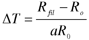
Cette opération permet de faire diffuser les dernières traces éventuelles d'argent dans la structure cristalline du fil de platine-rhodium. Si le décapage a été correctement effectué, l'argent résiduel étant présent en très faible quantité, le fil se stabilise au bout d'une journée et ne voit plus sa résistance évoluer.This operation makes it possible to diffuse the last possible traces of silver in the crystalline structure of platinum-rhodium wire. If the stripping was done correctly, the residual money being present in very small quantities, the wire stabilizes after one day and no longer sees its resistance evolve.
La partie active 14 d'un capteur selon l'invention est principalement constituée du fil 2, de très faible diamètre, de l'ordre de quelques dixièmes de µm (
On cherche donc à réaliser une condition d'alignement très forte entre les deux tronçons de gaine 22 qui se situent aux extrémités du fil 2 (
Un tel alignement est obtenu de la manière suivante.Such alignment is achieved in the following manner.
D'abord on veille à la rectitude du fil utilisé. Ce fil est en général conditionné sous forme enroulée autour d'une bobine de plusieurs cm de diamètre. Il s'avère qu'une tension de quelques grammes, par exemple d'environ 4 g, sur le fil déroulé est suffisante pour qu'il perde la mémoire de son enroulement. Cette valeur autorise la réalisation de sondes employant un fil 2 dont la partie active 14 a un diamètre de 0,625 µm. Par contre, pour les diamètres inférieurs (0,5 et 0,35 µm), cette tension s'avère insuffisante pour obtenir des conditions d'alignement qui font qu'il n'y ait pas rupture du fil après décapage. Un fil de diamètre 0,625 µm possède une résistance mécanique qui autorise un certain désalignement que ne supportent pas les fils de 0,5 et 0,35 µm. Par conséquent, pour la réalisation des sondes selon l'invention, la tension a, dans un premier temps, été augmentée pour la porter jusqu'à une valeur de 7 g. Cette solution n'a pas donné de résultats satisfaisants dans la mesure où l'excès de tension sur le fil 2 masque l'existence, lors de sa mise en place, d'un éventuel défaut d'alignement entre les broches 4, 6 et le fil 2 lui-même. Ce défaut peut se traduire, lors du décapage, par la rupture de la partie active 14, décelable seulement après coup. Pour contrer le phénomène de masquage de cet éventuel défaut d'alignement, il a fallu revenir à une tension inférieure à 7g, environ 4 g dans le cas considéré. Pour compenser le manque de tension, on effectue au préalable une opération de redressement du fil, par exemple en le faisant rouler entre une plaque de verre et un bloc de métal, dont l'état de surface est poli (cale étalon). Cette solution apporte de bons résultats.First we take care of the straightness of the wire used. This yarn is generally packaged in a form wrapped around a coil several cm in diameter. It turns out that a voltage of a few grams, for example about 4 g, on the unwound wire is sufficient to lose the memory of its winding. This value allows the production of probes using a
On cherche également à obtenir un très bon parallélisme le plan 43 contenant les deux génératrices de contact du fil 2 sur les cônes des broches 4, 6 et le fil en lui-même. Si ce parallélisme n'est pas respecté, le désalignement qui en résulte génère, après le brasage du fil sur les broches, une contrainte mécanique qui, en retour, détruit la partie active du fil après décapage.It is also sought to obtain a very good parallelism the
L'expérience montre que le défaut d'alignement toléré est de l'ordre du centième de millimètre pour une distance entre broches de 8 mm. Pour que cette condition soit bien vérifiée, la tension mécanique sur le fil testée est de préférence inférieure à quelques grammes, aux environs de 4 g.Experience shows that the misalignment tolerated is of the order of a hundredth of a millimeter for a distance between pins of 8 mm. For this condition to be well verified, the mechanical tension on the wire tested is preferably less than a few grams, around 4 g.
En ce qui concerne la nature de la brasure, des essais ont été réalisés avec des brasures étain-cuivre, qui conviennent pour des fils de diamètre supérieur à 0,625 µm.As regards the nature of the solder, tests have been carried out with tin-copper solders, which are suitable for wires with a diameter greater than 0.625 μm.
En revanche, il s'avère que, pour des diamètres inférieurs à 0,625 µm, la fabrication d'un capteur devient aléatoire. Après une analyse fine des conditions de réalisation et le recoupement des problèmes, il est apparu que la tenue mécanique de l'alliage étain-cuivre n'est pas suffisante, en particulier pour empêcher, lors de la découpe du fil, une rotation de ce dernier au niveau des broches, là où il doit normalement être considéré, du point de vue mécanique, comme encastré. Par voie de conséquence, ce déplacement relatif du fil sur les broches engendre un défaut d'alignement des deux parties gainées du fil. Ce désalignement peut conduire à la rupture du fil, après décapage.On the other hand, it turns out that, for diameters smaller than 0.625 μm, the manufacture of a sensor becomes random. After a detailed analysis of the conditions of realization and the overlapping of the problems, it appeared that the mechanical strength of the alloy tin-copper is not sufficient, in particular to prevent, during the cutting of the wire, a rotation of this last at the pins, where it should normally be considered, from the mechanical point of view, as recessed. As a result, this relative displacement of the wire on the pins causes a misalignment of the two sheathed portions of the wire. This misalignment can lead to breakage of the wire, after stripping.
Pour contourner l'effet de fluage que provoque l'effort qu'engendre une découpe avec une lame de rasoir au niveau des broches, on peut mettre en oeuvre d'autres moyens de découpe, par exemple un disque tournant à grande vitesse de rotation, de manière à rendre quasi-nul l'effort de cisaillement au niveau de la brasure. Ce procédé de découpe est tout à fait satisfaisant pour des sondes mono fil, mais devient inopérant pour des sondes multi fils. En effet, la phase de découpe à l'aide du disque met en évidence l'existence d'un liquide (que nous supposons être de lubrification, pour que, lors de la phase de fabrication, l'écrouissage entre la gaine 22 d'argent et l'âme 20 en platine-rhodium puisse se dérouler normalement). Ce dernier, en venant polluer les broches environnantes, rend leur brasage impossible.In order to circumvent the creep effect caused by the force generated by cutting with a razor blade at the pins, other cutting means may be used, for example a disk rotating at a high speed of rotation. in such a way as to render the shear stress at the level of the solder virtually zero. This cutting process is quite satisfactory for single-wire probes, but becomes ineffective for multi-wire probes. Indeed, the cutting phase using the disc shows the existence of a liquid (which we assume to be lubrication, so that during the manufacturing phase, hardening between the
L'utilisation d'une brasure à base d'alliage étain-plomb a permis de résoudre ce problème. Une telle brasure a une bien meilleure tenue mécanique et permet une découpe manuelle du fil par lame de rasoir, bien plus aisée à mettre en oeuvre, en particulier dans le cas de la sonde multifil.The use of tin-lead alloy solder has solved this problem. Such solder has a much better mechanical strength and allows manual cutting of the wire by razor blade, much easier to implement, especially in the case of the multi-wire probe.
Avec cette nouvelle brasure, la partie du fil située entre les broches ne souffre plus d'aucune contrainte liée à cette opération.With this new solder, the portion of the wire between the pins no longer suffers from any constraints related to this operation.
Au regard de la dimension caractéristique des éléments (diamètre du fil de l'ordre de 50 µm, extrémité des broches de l'ordre de 20 µm), la brasure est de préférence réalisée avec un pistolet 81 à air chaud (
Chronologiquement, l'activité de fabrication de sondes équipées de fils de très petits diamètres a débuté avec du fil de 0,625 µm. Pour les premières sondes, nous avons repris stricto sensu la méthode de fabrication que nous avions développée pour des sondes équipées de fil de 2,5 µm. De façon systématique, lors de la phase de décapage, il y avait rupture du fil de 0,625 µm. Un travail d'analyse a permis de mettre en évidence deux causes responsables de la rupture du fil, lorsque celle-ci se produit.Chronologically, the manufacturing activity of probes equipped with very small diameter wires started with 0.625 μm wire. For the first probes, we have taken stricto sensu the manufacturing method we had developed for probes equipped with 2.5 μm wire. In a systematic way, during the stripping phase, the wire was broken down by 0.625 μm. Analytical work has highlighted two causes responsible for the breakage of the wire, when it occurs.
La première concerne l'existence d'une tension mécanique résiduelle dans le fil de Wollaston, due au fait que le fil était installé sans tension préalable, ce qui n'annulait pas suffisamment la mémoire résiduelle de son enroulement sur la bobine de conditionnement. Comme déjà expliqué ci-dessus, une étape de rectification et une tension mécanique sur le fil de quelques grammes, (aux environs de 4 g) permettent de résoudre ce problème.The first concerns the existence of a residual mechanical stress in the Wollaston wire, due to the fact that the wire was installed without prior tension, which did not sufficiently cancel the residual memory of its winding on the conditioning coil. As already explained above, a grinding step and a mechanical tension on the wire a few grams, (about 4 g) can solve this problem.
La seconde cause est liée à un phénomène de dilatation thermique, qui n'a pu être mis en évidence de façon systématique que lorsque le fil fut préparé avec une tension mécanique. Lors du décapage, la partie active 14 du fil était toujours plus ou moins alignée avec les deux tronçons de gaines 22, mais au niveau de la rupture apparaissait un écart entre les deux parties du fil rompu. Cet écart était la signature de l'existence d'un phénomène de dilatation thermique.The second cause is related to a phenomenon of thermal expansion, which could be highlighted in a systematic way only when the wire was prepared with a mechanical tension. During pickling, the
Qualitativement, ce processus de tension thermomécanique dans le fil n'existe que parce que la constante de solidification de la brasure est plus faible que la constante de refroidissement du fil. A ceci s'ajoute la forte valeur de diffusivité de l'argent, qui fait que la longueur chauffée peut atteindre quelques millimètres durant le temps de liquéfaction de la brasure. En s'appuyant sur une modélisation simplifiée de la longueur chauffée sur le fil, de la différence de température subie par le fil et de la durée d'exposition à la source chaude, l'estimation du raccourcissement du fil après solidification de la brasure est de l'ordre de 10 µm. Pour neutraliser ce phénomène de tension thermomécanique, qui signifie à coup sûr la rupture de la partie active 14 du fil, on a, dans un premier temps, diminué la taille de la buse du fer 81 à air chaud, en pensant que cette solution allait contribuer à une diminution de l'échauffement du fil. Malheureusement cette option n'a pas donné de résultats satisfaisants ; en revanche, elle a fait apparaître un problème d'entraînement de la brasure sous la broche, lié à l'augmentation de la vitesse de l'air chaud en sortie de buse. On ne peut donc pas diminuer indéfiniment le diamètre de la buse, d'autant que pour une valeur trop faible de ce dernier, l'énergie cédée à la brasure n'est de surcroît plus suffisante pour assurer sa fusion.Qualitatively, this process of thermomechanical tension in the wire exists only because the solidification constant of the solder is lower than the constant of cooling of the wire. Added to this is the high diffusivity value of silver, which means that the heated length can reach a few millimeters during the liquefaction time of the solder. Based on a simplified modeling of the length heated on the wire, the temperature difference experienced by the wire and the duration of exposure to the hot source, the estimate of the shortening of the wire after solidification of the solder is of the order of 10 microns. To neutralize this phenomenon of thermomechanical tension, which certainly signifies the breaking of the
Une solution, qui prend en compte cet effet inéluctable de thermo-dilatation du fil, consiste à flamber légèrement une des broches 4, 6 avant le brasage, et à la relâcher ensuite, de manière à retrouver pour le fil une situation sans contrainte résiduelle.One solution, which takes into account this ineluctable effect of thermo-expansion of the wire, is to slightly flambé one of the
Cependant, la fabrication de sondes doubles à fils parallèles s'avère difficile à réaliser avec cette technique de brasage. La distance entre les deux fils n'est jamais suffisante pour qu'il n'y ait pas interaction du jet du fer 81 à air chaud, avec un premier fil déjà brasé, lors du brasage d'un second fil. Une réponse à ce problème consiste à implanter, dans l'espace entre les deux paires de broches, un écran thermique destiné à protéger le premier fil.However, the manufacture of dual probes with parallel wires proves difficult to achieve with this brazing technique. The distance between the two son is never sufficient for there to be no interaction of the
Une autre technique met en oeuvre un apport très localisé de puissance par rayon laser, dont la ponctualité présente l'avantage de ne pas polluer thermiquement l'environnement. Le laser employé est de mode impulsionnel, de type Yag avec une puissance maximale de 30W. La fréquence et la durée des impulsions sont réglables. On focalise le faisceau sur le point de brasure en bout de broche grâce à une caméra couplée au laser, et on effectue un tir qui entraîne la fusion de la brasure et couple le fil à la broche.Another technique uses a very localized power supply by laser beam, whose punctuality has the advantage of not polluting the environment thermally. The laser used is pulse mode, YAG type with a maximum power of 30W. The frequency and duration of the pulses are adjustable. We focus the beam on the point of soldering at the end of the spindle thanks to a camera coupled to the laser, and a shot is made which causes the fusion of the solder and couples the wire to the spindle.
La mise en oeuvre de cette technique permet d'assurer l'opération de brasure quels que soient le degré de miniaturisation de la sonde et le nombre de fils qu'elle comporte.The implementation of this technique ensures the brazing operation regardless of the degree of miniaturization of the probe and the number of son it comprises.
L'expérience montre que la manipulation de sondes devient très délicate dès lors que le diamètre des fils devient inférieur à 0,625 µm. En particulier lors du montage d'une sonde selon l'invention dans une soufflerie, des vibrations sont créées, qui constituent un élément critique pour la tenue du capteur car elles sont suffisantes pour créer une onde qui se propage dans les broches jusqu'au fil. A cause de sa faible résistance mécanique, la présence de la courbure de la partie active n'est plus suffisante pour amortir ces vibrations pouvant conduire à la rupture du fil. Il a été constaté que c'est par le corps de la sonde qu'est transmis l'essentiel des vibrations vers l'extrémité des broches, par exemple lors de son blocage sur son support à l'aide d'une vis.Experience shows that the manipulation of probes becomes very delicate as soon as the diameter of the wires becomes less than 0.625 μm. In particular when mounting a probe according to the invention in a wind tunnel, vibrations are created, which constitute a critical element for the holding of the sensor because they are sufficient to create a wave that propagates in the pins to the wire. . Because of its low mechanical strength, the presence of the curvature of the active part is no longer sufficient to dampen these vibrations may lead to the breaking of the wire. It has been found that it is through the body of the probe that most of the vibrations are transmitted towards the end of the pins, for example when it is blocked on its support by means of a screw.
La solution optimale pour protéger le fil a consisté à insérer le corps de sonde en céramique, une fois muni de ses broches, dans un fourreau amortisseur 12 de très faible dureté (de l'ordre de 25 shores A).The optimal solution for protecting the wire consisted in inserting the ceramic probe body, once provided with its pins, into a damping
Une sonde selon l'invention est utilisée avec des moyens d'alimentation en courant, et des moyens de mesure des variations de résistance électrique du fil, ou des fils. Ce sont ces variations qui traduisent les variations de vitesse et/ou de température d'un fluide que transporte un écoulement dans lequel la sonde est plongée.A probe according to the invention is used with current supply means, and means for measuring variations in electrical resistance of the wire or wires. These are these variations which translate the variations of speed and / or temperature of a fluid carried by a flow in which the probe is immersed.
D'une manière générale, pour la réalisation d'une mesure à la fois précise et reproductible, il est préférable d'utiliser une alimentation par des batteries. Ainsi on découple le système du réseau électrique, dont les potentiels peuvent fluctuer (du fait, par exemple, de la mise en marche ou de l'arrêt d'installations voisines). En outre les courants et/ou les tensions qui interviennent au niveau du capteur sont très faibles et peuvent être aisément perturbés par ces fluctuations du réseau, si petites soient elles.In general, for the realization of a measurement that is both accurate and reproducible, it is preferable to use a battery supply. Thus, the system is decoupled from the electrical network, whose potentials can fluctuate (for example, by starting or stopping neighboring installations). In addition, the currents and / or the voltages that occur at the sensor are very small and can be easily disturbed by these network fluctuations, however small.
Par ailleurs, dans des installations telles qu'une soufflerie, il est difficile de mettre correctement au même potentiel les différents points de masse. Il en résulte des courants de boucle entre ces différents points de masse, pilotés par les fluctuations de potentiel du réseau, courants qui perturbent également les mesures de manière importante.Moreover, in installations such as a wind tunnel, it is difficult to correctly put the same potential at different mass points. This results in loop currents between these different ground points, driven by the potential fluctuations of the network, currents which also disturb the measurements significantly.
Cette solution permet en outre d'alimenter tous les circuits, qui possèdent ainsi un potentiel de masse fixe et non plus fluctuant comme ce peut être le cas lorsqu'ils sont reliés à des régulateurs de tension électroniques.This solution also makes it possible to supply all the circuits, which thus have a fixed and not fluctuating ground potential, as can be the case when they are connected to electronic voltage regulators.
Pour assurer la compatibilité électromagnétique (CEM) les circuits sont de préférence placés dans une boîte, par exemple en cuivre, qui constitue un plan de masse, relié à la masse de la batterie. A ce plan de masse est également reliée une tresse entourant les fils de connexion de la sonde. Ainsi toutes les protections de ce type vis-à-vis des champs électromagnétiques sont reliées à un potentiel fixe.To ensure electromagnetic compatibility (EMC) the circuits are preferably placed in a box, for example copper, which constitutes a ground plane, connected to the ground of the battery. At this ground plane is also connected a braid surrounding the connection wires of the probe. Thus all protections of this type vis-à-vis electromagnetic fields are connected to a fixed potential.
Les solutions trouvées ci-dessus pour assurer d'une part une alimentation non perturbée et d'autre part une compatibilité électromagnétique s'appliquent à tout type de fonctionnement de l'anémomètre.The solutions found above to ensure on the one hand undisturbed power supply and on the other hand electromagnetic compatibility apply to any type of operation of the anemometer.
Un fonctionnement particulier est le fonctionnement dit « à fil froid ». Il s'agit d'un mode de fonctionnement courant constant, dans lequel le courant avec lequel on alimente le fil est très faible.A particular operation is the so-called "cold wire" operation. This is a constant current mode of operation, in which the current with which the wire is fed is very low.
On connaît déjà des anémomètres à fil froid.Cold wire anemometers are already known.
Dans ces dispositifs connus, l'alimentation comporte une grande résistance R placée en série avec le fil afin de conserver une intensité de courant Iw constante dans ce fil lorsque la vitesse de l'écoulement varie. Le fil est intégré à un pont de Wheatstone pour mesurer avec précision sa résistance Rw; le signal de sortie est recueilli au sommet du pont.In these known devices, the power supply has a large resistance R placed in series with the wire in order to maintain a constant current I w in this wire when the flow velocity varies. The wire is integrated with a Wheatstone bridge to accurately measure its Rw resistance ; the output signal is collected at the top of the bridge.
L'anémomètre à courant constant possède des avantages. On a le libre choix de la surchauffe, ce qui est très apprécié pour l'étude des fluctuations de température. On peut aussi mesurer le bruit de fond en substituant au fil une résistance fixe et apporter ensuite aux mesures les corrections qui seraient nécessaires. En contrepartie, on amplifie les signaux de sortie de façon importante. La bande passante de ce principe de mesure est imposée par l'inertie thermique du fil.The constant current anemometer has advantages. We have the choice of overheating, which is very appreciated for the study of temperature fluctuations. The background noise can also be measured by substituting a fixed resistance for the wire and then making the necessary corrections to the measurements. In return, the output signals are amplified significantly. The bandwidth of this Principle of measurement is imposed by the thermal inertia of the wire.
Dans ce type de fonctionnement, on fait tendre le courant qui alimente le fil vers une valeur nulle afin de chauffer ce dernier le moins possible. Le fil n'est donc plus refroidi par convection (dans la mesure où il n'est pas chauffé), et devient uniquement sensible à la température du milieu environnant T par le biais de la valeur de sa résistance Rfil selon la relation : ![]()
![]()
Dans ce type de fonctionnement, l'écart de température est faible et le courant avec lequel on alimente le fil est très faible. Il sert juste à pouvoir mesurer une tension aux bornes du fil afin de remonter à la valeur de sa résistance. Il est généralement de l'ordre de 50 à 200 µA. Ainsi, le chauffage du fil par effet Joule est négligeable, ce qui vaut à cet anémomètre le nom de thermomètre fil froid.In this type of operation, the temperature difference is small and the current with which the wire is fed is very small. It just serves to measure a voltage across the wire to get back to the value of its resistance. It is generally of the order of 50 to 200 μA. Thus, the heating of the wire by Joule effect is negligible, which is worth to this anemometer the name of cold wire thermometer.
Un problème posé par ce type de fonctionnement est le suivant : la température mesurée dérive, il est donc nécessaire d'associer la sonde à un thermocouple pour avoir une mesure de la température moyenne.A problem with this type of operation is as follows: the measured temperature drifts, it is necessary to associate the probe with a thermocouple to have a measurement of the average temperature.
L'invention propose une solution à ce problème.The invention proposes a solution to this problem.
Des moyens électroniques associés à un anémomètre courant constant sont représentés en
- des moyens d'alimentation 110, de préférence une batterie comme expliqué ci-dessus,
- une résistance de référence 112,
- un potentiomètre 114 pour le réglage du courant.
- supply means 110, preferably a battery as explained above,
- a
reference resistor 112, - a
potentiometer 114 for adjusting the current.
Plus précisément, l'alimentation du circuit Ve, représenté par la pile 110, est fournie par un régulateur de tension (MAX 6325). Les deux résistances 2, 112 sont montées en miroir de courant. Le réglage du courant traversant les deux branches du miroir, chacune des branches comportant l'une de ces deux résistances, est effectué par la tension Vbe d'un transistor de réglage 116, monté en diode, via le potentiomètre 114. La différence de potentiel entre la sonde 2 et la résistance de référence 112 est appliquée à un amplificateur opérationnel d'instrumentation 120. La sotie de l'amplification fournit un signal mesuré qui traduit les variations de la résistance du fil 2.More specifically, the supply of the circuit Ve, represented by the
Afin d'exploiter les informations de faible amplitude, on amplifie le signal aux bornes de la sonde 2. De préférence, et afin de tenir compte des limitations en tension des cartes d'acquisition, cette amplification n'est pas trop importante (on essaie de tenir compte de la résolution en tension de la carte d'acquisition). Or une sonde anémométrique 2 a une résistance importante, et les variations en sortie de l'anémomètre, après amplification, peuvent dépasser les plages d'utilisation des cartes. C'est pourquoi on choisit de centrer sur environ zéro le signal de sortie du thermomètre; ceci permet également de profiter au maximum de la gamme de mesure et de régler ainsi le gain en conséquence. Pour ce faire, on effectue une soustraction entre le signal aux bornes de la 2 sonde et le signal aux bornes d'une résistance de référence 112.In order to exploit the information of low amplitude, the signal is amplified at the terminals of the
Le montage à miroir de courant permet d'avoir un signal stable traversant la résistance de référence, ainsi qu'un courant stable traversant la sonde 2.The current mirror arrangement makes it possible to have a stable signal crossing the reference resistance, as well as a stable current passing through the
Un tel dispositif a été mis en oeuvre dans le cadre de campagnes d'essais dans une soufflerie, la sonde étant une sonde à un fil fonctionnant en fil froid.Such a device has been implemented in the context of test campaigns in a wind tunnel, the probe being a single-wire probe operating in cold wire.
Il a alors été remarqué une dérive des mesures de température moyenne, anormale d'après les conditions de mesure et la sonde 112 de référence, en platine, de l'installation. Il s'est avéré que cette dérive pouvait seulement provenir du circuit électronique. Les composants sont en effet sensibles à la température du milieu environnant, et une différence de température ambiante entre le local d'étalonnage et la soufflerie pouvait tout à fait expliquer les écarts observés.It was then noticed a drift of the average temperature measurements, abnormal according to the measurement conditions and the
Dans un premier temps la résistance de référence 112 a été remplacée par une résistance métallique dont le coefficient de variation avec la température est bien moindre (0,6 ppm/°C) et négligeable.At first, the
Des relevés des différentes tensions mises en jeu ont été effectués en plaçant le circuit électronique dans une étuve dont la température est suivie. On peut ainsi vérifier que le régulateur électronique de tension ne voit pas la valeur de la tension qu'il délivre varier avec la température (dérive de 5 µV.°C-1). Les deux tensions aux bornes de la résistance de référence et aux bornes d'une seconde résistance destinée à simuler la sonde ont montré une dérive, parfaitement coordonnée, de l'ordre de 250 µV.°C-1 (pour des résistances de 670 Ω). Ceci indique donc que le courant variait de manière simultanée et identique dans les deux branches du miroir de courant.Reports of the different voltages involved were made by placing the circuit electronics in an oven whose temperature is monitored. It can thus be verified that the electronic voltage regulator does not see the value of the voltage it delivers vary with the temperature (drift 5 μV ° C -1 ). The two voltages at the terminals of the reference resistor and at the terminals of a second resistor intended to simulate the probe showed a perfectly coordinated drift of the order of 250 μV ° C -1 (for resistances of 670 Ω ). This indicates that the current varied simultaneously and identically in both branches of the current mirror.
On s'est donc intéressé à la valeur de la tension Vbe qui fixe ce courant. Un relevé dans les mêmes conditions a indiqué une dérive de cette tension de 2,4 mV.°C-1. Cette dérive trouve son origine dans le fait que le transistor 116 concerné par cette tension est monté en diode; or la dérive de tension usuellement observée aux bornes d'une diode est de 2,5 mV.°C-1 environ, ce qui concorde parfaitement avec nos relevés.It is therefore interested in the value of the voltage Vbe which sets this current. A survey under the same conditions indicated a drift of this voltage of 2.4 mV ° C -1 . This drift originates in the fact that the
Pour annuler cette dérive, on maintient les composants du thermomètre (la sonde et ses moyens d'alimentation et de mesure) à une température constante. Par exemple, on régule électroniquement la puissance d'un tapis chauffant placé dans le boîtier de l'anémomètre.To cancel this drift, the thermometer components (the probe and its supply and measurement means) are kept at a constant temperature. For example, the power of a heating mat placed in the housing of the anemometer is electronically regulated.
Le circuit électronique du thermomètre est ainsi maintenu à une température supérieure à celle du local dans lequel il se trouve. Cette température à laquelle le circuit est maintenu est régulée à plus ou moins un dixième de degré. Ainsi, non seulement les composants qui constituent l'anémomètre ne dérivent pas, mais ils fonctionnent dans des conditions reproductibles.The electronic circuit of the thermometer is thus maintained at a temperature greater than that of the room in which it is located. This temperature at which the circuit is maintained is regulated to plus or minus one-tenth of a degree. Thus, not only the components constituting the anemometer do not drift not, but they work under reproducible conditions.
Ce dispositif permet, après un unique étalonnage de l'ensemble de la chaîne anémométrique, de mesurer dans l'écoulement non seulement les fluctuations de la température, mais aussi sa valeur moyenne, ce qui est un résultat inédit. En effet, même dans les cas des dispositifs connus pour lesquels un soin particulier est apporté à la métrologie et à la mesure (c'est notamment le cas des mesures de température en sortie d'un jet rapportées par
Le circuit décrit dans cette partie est applicable à une sonde à plusieurs fils. On peut réaliser autant de circuits que nécessaire.The circuit described in this part is applicable to a multi-wire probe. We can make as many circuits as necessary.
Un exemple d'étalonnage et d'utilisation va maintenant être donné.An example of calibration and use will now be given.
Les étalonnages sont effectués dans une soufflerie. L'air passe successivement dans une boîte chauffante et un échangeur à eau dont la puissance et le débit peuvent être indépendamment réglés afin d'obtenir les niveaux de température souhaités, entre la température ambiante et 150°C environ.Calibrations are performed in a wind tunnel. The air passes successively in a heating box and a water exchanger whose power and flow can be independently adjusted to obtain the desired temperature levels, between room temperature and about 150 ° C.
La sonde 2 à fil froid est placée dans la veine d'étalonnage (entourée d'un anneau de garde thermique), au centre de la sortie d'une buse d'injection de l'air. La température de l'enceinte est donnée avec une précision du dixième de degré par une sonde Pt100 de référence associée à un boîtier électronique de mesure (référence : Sfere DGN75T).The
Pour chaque point d'étalonnage, un point de fonctionnement de la boîte chauffante et de l'échangeur est choisi. On laisse ensuite l'équilibre thermique s'établir entre l'air et les parois de la soufflerie, opération qui prend plusieurs heures (typiquement 4) . On effectue ensuite un relevé de la tension délivrée par le thermomètre pendant une trentaine de secondes, valeur largement suffisante pour obtenir une convergence de la mesure.For each calibration point, an operating point of the heating box and exchanger is selected. The thermal equilibrium is then allowed to settle between the air and the walls of the blower, an operation that takes several hours (typically 4). The voltage delivered by the thermometer is then measured for about thirty seconds, a value that is largely sufficient to obtain a convergence of the measurement.
L'opération est répétée cinq fois pour obtenir les coefficients d'étalonnage de la dépendance linéaire de la tension de sortie du thermomètre en fonction de la température du fluide : ![]()
![]()
Un exemple typique d'étalonnage est présenté sur la
Sur la
La courbe II représente la densité spectrale d'énergie du signal de tension en sortie du thermomètre avec une résistance branchée à la place de la sonde à fil. Cette densité représente donc le bruit du thermomètre.Curve II represents the spectral energy density of the voltage signal at the output of the thermometer with a resistor connected in place of the lead probe. This density therefore represents the noise of the thermometer.
Entre les plus grosses échelles captées par le thermomètre et le bruit de ce dernier, on peut observer sur ce tracé une différence de 7 décades, soit un rapport dans ce cas entre grandes et petites échelles discernables de l'ordre de 3000. En d'autres termes, la résolution du thermomètre dans ce cas est d'environ 5.10-3 °C.Between the largest scales captured by the thermometer and the noise of the latter, we can observe on this plot a difference of 7 decades, a ratio in this case between large and small scales discernable of the order of 3000. In d ' other words, the resolution of the thermometer in this case is about 5.10 -3 ° C.
Une telle résolution et une densité spectrale d'énergie présentant une amplitude aussi importante entre grandes et petites échelles constituent des performances inédites.Such a resolution and an energy spectral density having such a large amplitude between large and small scales constitute unprecedented performances.
Pour des mesures en situation non établie (impact de jet chauffé sur une paroi), la sonde selon l'invention permet de réaliser des mesures sans correction.For measurements in non-established situation (jet impact heated on a wall), the probe according to the invention makes it possible to perform measurements without correction.
En outre, l'invention propose un perfectionnement aux thermomètres, pour les rendre stables pour en augmenter fortement la sensibilité. On dispose ainsi d'un thermo-anémomètre possédant un rapport signal sur bruit avéré de plusieurs milliers (3500 pour le thermomètre et 10000 pour l'anémomètre à tension constante) quand il est associé à une sonde à fils de petit diamètre selon l'invention.In addition, the invention provides an improvement to the thermometers, to make them stable to greatly increase the sensitivity. There is thus a thermo-anemometer having a signal-to-noise ratio of several thousand (3500 for the thermometer and 10000 for the constant-voltage anemometer) when it is associated with a small diameter wire probe according to the invention. .
L'invention permet de réaliser un fonctionnement d'un anémomètre à fil froid, sans thermocouple, pour avoir une mesure de la température moyenne. Le circuit de régulation proposé permet de compenser la dérive et de s'affranchir d'un thermocouple.The invention makes it possible to perform an operation of a cold wire anemometer, without thermocouple, to have a measurement of the temperature average. The proposed regulation circuit makes it possible to compensate the drift and to get rid of a thermocouple.
Le circuit de régulation proposé ici peut être appliqué à une sonde selon l'invention, décrite ci dessus en liaison avec les
Claims (15)
- Anemometer probe having a single wire, or n wires (n>1) that are parallel to each other, for a measurement close to a wall, comprising, for each wire:a) two pins (4, 6) for holding the wire in place, each pin having a body (41) that is substantially cylindrical, said body being made thinner and truncated at the end thereof by a plane (43), which cuts across a direction (AA') along which the pin substantially extends, thus forming a flat zone (43) for positioning and fastening the wire;b) a straight portion of wire (2) brazed onto said flat zones (43) for positioning and fastening the wire.
- Probe according to the previous claim, wherein at least one of the wires comprises a central core (20) of diameter d, for example in the range 0.35 to 0.6 µm, and a sheath (22), cut away over a portion of wire, called a sensing zone, of length l, capable of being between 0.4 mm and 0.5 mm, where l/d lies in the range 600 to 1,500.
- Probe according to either claim 1 or claim 2, wherein at least one of the wires (2) is brazed on the pins (4, 6) using a tin-lead type brazing alloy.
- Probe according to one of claims 1 to 3, wherein at least one of the wires has a bending and/or the wires are separated by a distance of between 0.2 mm and 1 mm, or between 0.3 mm and 0.8 mm.
- Probe according to one of claims 1 to 4, wherein the pins are fastened onto a probe body (10) provided with a vibration absorbing casing (12) and/or separated by a distance at least equal to 4 mm.
- Method of producing an anemometer probe having a single wire, or n wires (n>1) that are parallel to each other, for a measurement close to a wall, comprising, for at least one of the wires:a) the positioning of a straight portion of the wire (2), comprising a metal core (20) of diameter d, surrounded by a protective sheath (22), on two pins (4, 6), each pin having a body (41) that is substantially cylindrical, said body being made thinner and truncated at the end thereof by a plane (43), which cuts across a direction (AA') along which the pin substantially extends, thus forming a flat zone (43) for positioning and fastening the wire;b) the brazing of the wire on each of the pins;c) the cutting away of one portion of the sheath (22), so as to reveal an active zone (14) for measuring the wire of length I.
- Method according to the previous claim, wherein step b) comprises the mechanical stressing and/or the formation of a bending of the wire, for example, according to the following steps:- performing a first brazing on a first pin (4),- distancing the ends of the two pins relative to each other,- performing the second first brazing on the second pin (6),- releasing the ends of the two pins.
- Method according to either claim 6 or claim 7, wherein step c) comprises a pickling step, or two pickling steps comprising:- a first acid pickling step,- a second electrochemical pickling step.
- Method according to claim 8, comprising a measurement of the strength of the wire in order to determine the pickled length.
- Method according to one of claims 8 or 9, wherein pickling is performed using a loop formed from a wire (101) on which a drop (102) of pickling solution can be held in place.
- Method according to one of claims 6 to 10, further comprising an annealing step at a temperature that is substantially greater than the temperature at which the wire is intended to be used.
- Method according to one of claims 6 to 11, wherein the brazing is performed using a heat gun (81), or by laser impact.
- Method according to one of claims 6 to 11, comprising a prior wire adjustment step, taking place before step a).
- Method according to one of claims 6 to 13, wherein at least one of the wires has a l/d ratio of between 600 to 1,500, and/or wherein the wires are separated by a distance of between 2.2 mm and 1 mm, or between 0.3 mm and 0.8 mm.
- Method for measuring the velocity of a fluid, for example near a wall, implementing an anemometer probe according to one of claims 1 to 5.
Applications Claiming Priority (2)
| Application Number | Priority Date | Filing Date | Title |
|---|---|---|---|
| FR0858871A FR2940452B1 (en) | 2008-12-19 | 2008-12-19 | ANEMOMETRIC PROBE AND METHOD FOR PRODUCING THE SAME |
| PCT/EP2009/067573 WO2010070116A1 (en) | 2008-12-19 | 2009-12-18 | Anemometer probe and method of production |
Publications (2)
| Publication Number | Publication Date |
|---|---|
| EP2368126A1 EP2368126A1 (en) | 2011-09-28 |
| EP2368126B1 true EP2368126B1 (en) | 2018-01-24 |
Family
ID=40902871
Family Applications (1)
| Application Number | Title | Priority Date | Filing Date |
|---|---|---|---|
| EP09795772.4A Not-in-force EP2368126B1 (en) | 2008-12-19 | 2009-12-18 | Anemometer probe and method of production |
Country Status (3)
| Country | Link |
|---|---|
| EP (1) | EP2368126B1 (en) |
| FR (1) | FR2940452B1 (en) |
| WO (1) | WO2010070116A1 (en) |
Families Citing this family (1)
| Publication number | Priority date | Publication date | Assignee | Title |
|---|---|---|---|---|
| WO2023047433A1 (en) * | 2021-09-23 | 2023-03-30 | The University Of Jordan | Dental pluripotent stem cells |
Family Cites Families (1)
| Publication number | Priority date | Publication date | Assignee | Title |
|---|---|---|---|---|
| US4517735A (en) * | 1983-10-28 | 1985-05-21 | Airsensors, Inc. | Apparatus and method for tensioning resistive wire |
-
2008
- 2008-12-19 FR FR0858871A patent/FR2940452B1/en not_active Expired - Fee Related
-
2009
- 2009-12-18 WO PCT/EP2009/067573 patent/WO2010070116A1/en active Application Filing
- 2009-12-18 EP EP09795772.4A patent/EP2368126B1/en not_active Not-in-force
Also Published As
| Publication number | Publication date |
|---|---|
| EP2368126A1 (en) | 2011-09-28 |
| FR2940452A1 (en) | 2010-06-25 |
| WO2010070116A1 (en) | 2010-06-24 |
| FR2940452B1 (en) | 2011-02-11 |
Similar Documents
| Publication | Publication Date | Title |
|---|---|---|
| EP2368125B1 (en) | Apparatus for regulating a wire anemometer | |
| FR2630210A1 (en) | METHOD AND DEVICE FOR MEASURING THE DISTRIBUTION OF THERMAL FLOW AND COEFFICIENT OF HEAT TRANSFER ON THE SURFACE OF A COOLED COMPONENT USED IN A HIGH TEMPERATURE ENVIRONMENT | |
| WO2010070119A1 (en) | Anemometer probe having one or more wires and its method of production | |
| EP2368126B1 (en) | Anemometer probe and method of production | |
| US10976188B2 (en) | Thermal flow measuring device including probe having probe core with hard solder | |
| CN112964386B (en) | Optical fiber FP resonant cavity temperature sensor and manufacturing method thereof | |
| Osorio et al. | Fabrication of hot-wire probes and electronics for constant temperature anemometers | |
| FR2787050A1 (en) | METAL CUTTING INSTALLATION PROVIDED WITH A CUTTING TORCH AND A CAPACITATION PROBE | |
| FR2706610A1 (en) | Heat flow sensor and associated measuring device | |
| EP0026126A1 (en) | Method of measuring a continuous neutron flux and device for carrying out this method | |
| Rout et al. | Characterization of High-Frequency Thermal Sensor for Transient Temperature Measurement | |
| Mekawy et al. | Refinement of Thermal Conduction-Based Dew Condensation Detection on Target Solid Surface by Galvanic Arrays Sensor Chip | |
| FR2496871A1 (en) | Measurement of narrow gap between two hot metal workpieces - by determn. of capacitance between surface of one piece and metal sensor located on other piece | |
| EP3172512B1 (en) | Method and system for detecting ice | |
| JPH1168195A (en) | Laser output monitor | |
| Lee et al. | Novel high-precision micropipette thermal sensor for materials thermal characterizations | |
| Shrestha et al. | Measurement of thermal conductivity of thin and thick films by steady-state heat conduction | |
| WO2016189231A1 (en) | Detector and associated manufacturing method | |
| FR2680572A1 (en) | Temperature probe for gas flow | |
| BE524743A (en) | ||
| WO2000006982A1 (en) | Device for contactless and continuous measurement of a moving elongated object temperature heated by radiation | |
| JPH0815048A (en) | Temperature measuring device |
Legal Events
| Date | Code | Title | Description |
|---|---|---|---|
| PUAI | Public reference made under article 153(3) epc to a published international application that has entered the european phase |
Free format text: ORIGINAL CODE: 0009012 |
|
| 17P | Request for examination filed |
Effective date: 20110624 |
|
| AK | Designated contracting states |
Kind code of ref document: A1 Designated state(s): AT BE BG CH CY CZ DE DK EE ES FI FR GB GR HR HU IE IS IT LI LT LU LV MC MK MT NL NO PL PT RO SE SI SK SM TR |
|
| DAX | Request for extension of the european patent (deleted) | ||
| 17Q | First examination report despatched |
Effective date: 20160831 |
|
| GRAP | Despatch of communication of intention to grant a patent |
Free format text: ORIGINAL CODE: EPIDOSNIGR1 |
|
| INTG | Intention to grant announced |
Effective date: 20170712 |
|
| GRAJ | Information related to disapproval of communication of intention to grant by the applicant or resumption of examination proceedings by the epo deleted |
Free format text: ORIGINAL CODE: EPIDOSDIGR1 |
|
| GRAR | Information related to intention to grant a patent recorded |
Free format text: ORIGINAL CODE: EPIDOSNIGR71 |
|
| GRAS | Grant fee paid |
Free format text: ORIGINAL CODE: EPIDOSNIGR3 |
|
| INTC | Intention to grant announced (deleted) | ||
| GRAA | (expected) grant |
Free format text: ORIGINAL CODE: 0009210 |
|
| AK | Designated contracting states |
Kind code of ref document: B1 Designated state(s): AT BE BG CH CY CZ DE DK EE ES FI FR GB GR HR HU IE IS IT LI LT LU LV MC MK MT NL NO PL PT RO SE SI SK SM TR |
|
| INTG | Intention to grant announced |
Effective date: 20171219 |
|
| REG | Reference to a national code |
Ref country code: GB Ref legal event code: FG4D Free format text: NOT ENGLISH |
|
| REG | Reference to a national code |
Ref country code: CH Ref legal event code: EP |
|
| REG | Reference to a national code |
Ref country code: AT Ref legal event code: REF Ref document number: 966078 Country of ref document: AT Kind code of ref document: T Effective date: 20180215 |
|
| REG | Reference to a national code |
Ref country code: IE Ref legal event code: FG4D Free format text: LANGUAGE OF EP DOCUMENT: FRENCH |
|
| REG | Reference to a national code |
Ref country code: DE Ref legal event code: R096 Ref document number: 602009050579 Country of ref document: DE |
|
| REG | Reference to a national code |
Ref country code: NL Ref legal event code: MP Effective date: 20180124 |
|
| REG | Reference to a national code |
Ref country code: LT Ref legal event code: MG4D |
|
| REG | Reference to a national code |
Ref country code: AT Ref legal event code: MK05 Ref document number: 966078 Country of ref document: AT Kind code of ref document: T Effective date: 20180124 |
|
| PG25 | Lapsed in a contracting state [announced via postgrant information from national office to epo] |
Ref country code: NL Free format text: LAPSE BECAUSE OF FAILURE TO SUBMIT A TRANSLATION OF THE DESCRIPTION OR TO PAY THE FEE WITHIN THE PRESCRIBED TIME-LIMIT Effective date: 20180124 |
|
| PG25 | Lapsed in a contracting state [announced via postgrant information from national office to epo] |
Ref country code: ES Free format text: LAPSE BECAUSE OF FAILURE TO SUBMIT A TRANSLATION OF THE DESCRIPTION OR TO PAY THE FEE WITHIN THE PRESCRIBED TIME-LIMIT Effective date: 20180124 Ref country code: LT Free format text: LAPSE BECAUSE OF FAILURE TO SUBMIT A TRANSLATION OF THE DESCRIPTION OR TO PAY THE FEE WITHIN THE PRESCRIBED TIME-LIMIT Effective date: 20180124 Ref country code: CY Free format text: LAPSE BECAUSE OF FAILURE TO SUBMIT A TRANSLATION OF THE DESCRIPTION OR TO PAY THE FEE WITHIN THE PRESCRIBED TIME-LIMIT Effective date: 20180124 Ref country code: FI Free format text: LAPSE BECAUSE OF FAILURE TO SUBMIT A TRANSLATION OF THE DESCRIPTION OR TO PAY THE FEE WITHIN THE PRESCRIBED TIME-LIMIT Effective date: 20180124 Ref country code: HR Free format text: LAPSE BECAUSE OF FAILURE TO SUBMIT A TRANSLATION OF THE DESCRIPTION OR TO PAY THE FEE WITHIN THE PRESCRIBED TIME-LIMIT Effective date: 20180124 Ref country code: NO Free format text: LAPSE BECAUSE OF FAILURE TO SUBMIT A TRANSLATION OF THE DESCRIPTION OR TO PAY THE FEE WITHIN THE PRESCRIBED TIME-LIMIT Effective date: 20180424 |
|
| PG25 | Lapsed in a contracting state [announced via postgrant information from national office to epo] |
Ref country code: PL Free format text: LAPSE BECAUSE OF FAILURE TO SUBMIT A TRANSLATION OF THE DESCRIPTION OR TO PAY THE FEE WITHIN THE PRESCRIBED TIME-LIMIT Effective date: 20180124 Ref country code: AT Free format text: LAPSE BECAUSE OF FAILURE TO SUBMIT A TRANSLATION OF THE DESCRIPTION OR TO PAY THE FEE WITHIN THE PRESCRIBED TIME-LIMIT Effective date: 20180124 Ref country code: BG Free format text: LAPSE BECAUSE OF FAILURE TO SUBMIT A TRANSLATION OF THE DESCRIPTION OR TO PAY THE FEE WITHIN THE PRESCRIBED TIME-LIMIT Effective date: 20180424 Ref country code: GR Free format text: LAPSE BECAUSE OF FAILURE TO SUBMIT A TRANSLATION OF THE DESCRIPTION OR TO PAY THE FEE WITHIN THE PRESCRIBED TIME-LIMIT Effective date: 20180425 Ref country code: IS Free format text: LAPSE BECAUSE OF FAILURE TO SUBMIT A TRANSLATION OF THE DESCRIPTION OR TO PAY THE FEE WITHIN THE PRESCRIBED TIME-LIMIT Effective date: 20180524 Ref country code: LV Free format text: LAPSE BECAUSE OF FAILURE TO SUBMIT A TRANSLATION OF THE DESCRIPTION OR TO PAY THE FEE WITHIN THE PRESCRIBED TIME-LIMIT Effective date: 20180124 Ref country code: SE Free format text: LAPSE BECAUSE OF FAILURE TO SUBMIT A TRANSLATION OF THE DESCRIPTION OR TO PAY THE FEE WITHIN THE PRESCRIBED TIME-LIMIT Effective date: 20180124 |
|
| PG25 | Lapsed in a contracting state [announced via postgrant information from national office to epo] |
Ref country code: MT Free format text: LAPSE BECAUSE OF FAILURE TO SUBMIT A TRANSLATION OF THE DESCRIPTION OR TO PAY THE FEE WITHIN THE PRESCRIBED TIME-LIMIT Effective date: 20180124 |
|
| REG | Reference to a national code |
Ref country code: DE Ref legal event code: R097 Ref document number: 602009050579 Country of ref document: DE |
|
| PG25 | Lapsed in a contracting state [announced via postgrant information from national office to epo] |
Ref country code: RO Free format text: LAPSE BECAUSE OF FAILURE TO SUBMIT A TRANSLATION OF THE DESCRIPTION OR TO PAY THE FEE WITHIN THE PRESCRIBED TIME-LIMIT Effective date: 20180124 Ref country code: EE Free format text: LAPSE BECAUSE OF FAILURE TO SUBMIT A TRANSLATION OF THE DESCRIPTION OR TO PAY THE FEE WITHIN THE PRESCRIBED TIME-LIMIT Effective date: 20180124 Ref country code: IT Free format text: LAPSE BECAUSE OF FAILURE TO SUBMIT A TRANSLATION OF THE DESCRIPTION OR TO PAY THE FEE WITHIN THE PRESCRIBED TIME-LIMIT Effective date: 20180124 |
|
| PG25 | Lapsed in a contracting state [announced via postgrant information from national office to epo] |
Ref country code: DK Free format text: LAPSE BECAUSE OF FAILURE TO SUBMIT A TRANSLATION OF THE DESCRIPTION OR TO PAY THE FEE WITHIN THE PRESCRIBED TIME-LIMIT Effective date: 20180124 Ref country code: SM Free format text: LAPSE BECAUSE OF FAILURE TO SUBMIT A TRANSLATION OF THE DESCRIPTION OR TO PAY THE FEE WITHIN THE PRESCRIBED TIME-LIMIT Effective date: 20180124 Ref country code: SK Free format text: LAPSE BECAUSE OF FAILURE TO SUBMIT A TRANSLATION OF THE DESCRIPTION OR TO PAY THE FEE WITHIN THE PRESCRIBED TIME-LIMIT Effective date: 20180124 Ref country code: CZ Free format text: LAPSE BECAUSE OF FAILURE TO SUBMIT A TRANSLATION OF THE DESCRIPTION OR TO PAY THE FEE WITHIN THE PRESCRIBED TIME-LIMIT Effective date: 20180124 |
|
| PLBE | No opposition filed within time limit |
Free format text: ORIGINAL CODE: 0009261 |
|
| STAA | Information on the status of an ep patent application or granted ep patent |
Free format text: STATUS: NO OPPOSITION FILED WITHIN TIME LIMIT |
|
| 26N | No opposition filed |
Effective date: 20181025 |
|
| PG25 | Lapsed in a contracting state [announced via postgrant information from national office to epo] |
Ref country code: SI Free format text: LAPSE BECAUSE OF FAILURE TO SUBMIT A TRANSLATION OF THE DESCRIPTION OR TO PAY THE FEE WITHIN THE PRESCRIBED TIME-LIMIT Effective date: 20180124 |
|
| REG | Reference to a national code |
Ref country code: CH Ref legal event code: PL |
|
| PG25 | Lapsed in a contracting state [announced via postgrant information from national office to epo] |
Ref country code: MC Free format text: LAPSE BECAUSE OF FAILURE TO SUBMIT A TRANSLATION OF THE DESCRIPTION OR TO PAY THE FEE WITHIN THE PRESCRIBED TIME-LIMIT Effective date: 20180124 Ref country code: LU Free format text: LAPSE BECAUSE OF NON-PAYMENT OF DUE FEES Effective date: 20181218 |
|
| REG | Reference to a national code |
Ref country code: IE Ref legal event code: MM4A |
|
| REG | Reference to a national code |
Ref country code: BE Ref legal event code: MM Effective date: 20181231 |
|
| PG25 | Lapsed in a contracting state [announced via postgrant information from national office to epo] |
Ref country code: IE Free format text: LAPSE BECAUSE OF NON-PAYMENT OF DUE FEES Effective date: 20181218 |
|
| PG25 | Lapsed in a contracting state [announced via postgrant information from national office to epo] |
Ref country code: BE Free format text: LAPSE BECAUSE OF NON-PAYMENT OF DUE FEES Effective date: 20181231 |
|
| PG25 | Lapsed in a contracting state [announced via postgrant information from national office to epo] |
Ref country code: CH Free format text: LAPSE BECAUSE OF NON-PAYMENT OF DUE FEES Effective date: 20181231 Ref country code: LI Free format text: LAPSE BECAUSE OF NON-PAYMENT OF DUE FEES Effective date: 20181231 |
|
| PG25 | Lapsed in a contracting state [announced via postgrant information from national office to epo] |
Ref country code: TR Free format text: LAPSE BECAUSE OF FAILURE TO SUBMIT A TRANSLATION OF THE DESCRIPTION OR TO PAY THE FEE WITHIN THE PRESCRIBED TIME-LIMIT Effective date: 20180124 |
|
| PG25 | Lapsed in a contracting state [announced via postgrant information from national office to epo] |
Ref country code: PT Free format text: LAPSE BECAUSE OF FAILURE TO SUBMIT A TRANSLATION OF THE DESCRIPTION OR TO PAY THE FEE WITHIN THE PRESCRIBED TIME-LIMIT Effective date: 20180124 |
|
| PG25 | Lapsed in a contracting state [announced via postgrant information from national office to epo] |
Ref country code: HU Free format text: LAPSE BECAUSE OF FAILURE TO SUBMIT A TRANSLATION OF THE DESCRIPTION OR TO PAY THE FEE WITHIN THE PRESCRIBED TIME-LIMIT; INVALID AB INITIO Effective date: 20091218 Ref country code: MK Free format text: LAPSE BECAUSE OF NON-PAYMENT OF DUE FEES Effective date: 20180124 |
|
| PGFP | Annual fee paid to national office [announced via postgrant information from national office to epo] |
Ref country code: DE Payment date: 20201209 Year of fee payment: 12 Ref country code: GB Payment date: 20201217 Year of fee payment: 12 Ref country code: FR Payment date: 20201228 Year of fee payment: 12 |
|
| REG | Reference to a national code |
Ref country code: DE Ref legal event code: R119 Ref document number: 602009050579 Country of ref document: DE |
|
| GBPC | Gb: european patent ceased through non-payment of renewal fee |
Effective date: 20211218 |
|
| PG25 | Lapsed in a contracting state [announced via postgrant information from national office to epo] |
Ref country code: GB Free format text: LAPSE BECAUSE OF NON-PAYMENT OF DUE FEES Effective date: 20211218 Ref country code: DE Free format text: LAPSE BECAUSE OF NON-PAYMENT OF DUE FEES Effective date: 20220701 |
|
| PG25 | Lapsed in a contracting state [announced via postgrant information from national office to epo] |
Ref country code: FR Free format text: LAPSE BECAUSE OF NON-PAYMENT OF DUE FEES Effective date: 20211231 |