EP0766265A2 - Verfahren und Vorrichtung zum Messen mindestens einer charakterisierenden Länge eines Brennstabs an der Peripherie eines Kernbrennstabbündels - Google Patents
Verfahren und Vorrichtung zum Messen mindestens einer charakterisierenden Länge eines Brennstabs an der Peripherie eines Kernbrennstabbündels Download PDFInfo
- Publication number
- EP0766265A2 EP0766265A2 EP96401925A EP96401925A EP0766265A2 EP 0766265 A2 EP0766265 A2 EP 0766265A2 EP 96401925 A EP96401925 A EP 96401925A EP 96401925 A EP96401925 A EP 96401925A EP 0766265 A2 EP0766265 A2 EP 0766265A2
- Authority
- EP
- European Patent Office
- Prior art keywords
- probe
- fuel
- plug
- axial direction
- sheath
- Prior art date
- Legal status (The legal status is an assumption and is not a legal conclusion. Google has not performed a legal analysis and makes no representation as to the accuracy of the status listed.)
- Granted
Links
Images


Classifications
-
- G—PHYSICS
- G01—MEASURING; TESTING
- G01B—MEASURING LENGTH, THICKNESS OR SIMILAR LINEAR DIMENSIONS; MEASURING ANGLES; MEASURING AREAS; MEASURING IRREGULARITIES OF SURFACES OR CONTOURS
- G01B7/00—Measuring arrangements characterised by the use of electric or magnetic techniques
- G01B7/14—Measuring arrangements characterised by the use of electric or magnetic techniques for measuring distance or clearance between spaced objects or spaced apertures
-
- G—PHYSICS
- G21—NUCLEAR PHYSICS; NUCLEAR ENGINEERING
- G21C—NUCLEAR REACTORS
- G21C17/00—Monitoring; Testing ; Maintaining
- G21C17/06—Devices or arrangements for monitoring or testing fuel or fuel elements outside the reactor core, e.g. for burn-up, for contamination
-
- Y—GENERAL TAGGING OF NEW TECHNOLOGICAL DEVELOPMENTS; GENERAL TAGGING OF CROSS-SECTIONAL TECHNOLOGIES SPANNING OVER SEVERAL SECTIONS OF THE IPC; TECHNICAL SUBJECTS COVERED BY FORMER USPC CROSS-REFERENCE ART COLLECTIONS [XRACs] AND DIGESTS
- Y02—TECHNOLOGIES OR APPLICATIONS FOR MITIGATION OR ADAPTATION AGAINST CLIMATE CHANGE
- Y02E—REDUCTION OF GREENHOUSE GAS [GHG] EMISSIONS, RELATED TO ENERGY GENERATION, TRANSMISSION OR DISTRIBUTION
- Y02E30/00—Energy generation of nuclear origin
- Y02E30/30—Nuclear fission reactors
Definitions
- the invention relates to a method and a device for measuring a characteristic length on a rod of a nuclear fuel assembly.
- Nuclear fuel assemblies for water-cooled reactors and in particular for pressurized water-cooled nuclear reactors have a framework in which the rods are held in the form of a bundle in which the rods are all parallel to each other.
- Each of the rods in the bundle of the nuclear fuel assembly comprises a tubular sheath whose diameter is close to, for example, one centimeter and whose length can be of the order of four meters.
- the sheath is made of a material which weakly absorbs neutrons such as a zirconium alloy.
- the nuclear combustible material which can consist of uranium oxide enriched in fissile uranium is placed inside the cladding in the form of a column of sintered pellets of combustible material stacked one on the other in the axial direction of the sheath.
- the pencil sheath is closed at a first end by a plug engaged in the end part of the pencil sheath and welded to the sheath.
- the column of pellets of combustible material placed inside the sheath rests at one of its ends on a substantially flat surface of the plug internal to the sheath.
- This first plug of the fuel rod on which the column of pellets made of combustible material rests constitutes the lower plug of the pencil, when the pencil is placed inside a fuel assembly in the service position in the core of a nuclear reactor or in storage position in a swimming pool.
- a second plug called the top plug is engaged and welded to the second end of the pencil sheath, this second plug also comprising a surface directed towards the inside of the sheath.
- the column of pellets of combustible material has a length less than the length of the internal space of the pencil sheath between the internal surface of the lower plug and the internal surface of the upper plug.
- the column of pellets made of combustible material is held inside the sheath by a helical spring interposed between the internal surface of the upper plug and the upper end of the column of pellets opposite the end of the column resting on the plug. inferior.
- the fuel rods are subjected to a neutron flux which makes it possible to produce energy in the combustible material of the rods by nuclear reactions.
- the neutrons produced by nuclear reactions in the pellets of combustible material constitute the flow of neutrons inside the core of the nuclear reactor.
- the pellets of combustible material undergo, due to nuclear reactions and heating in the reactor core, expansions and swelling which can cause deformation of the pencil sheath.
- the thermal and mechanical stresses to which the fuel rods of nuclear fuel assemblies are subjected in the core of the nuclear reactor can cause deterioration which is added to the normal wear of the fuel by consumption of the fissile material, so that at least part of the fuel rods of the assemblies becomes unfit for use in the fuel assemblies of the core, after a certain time of stay in the core of the reactor in operation.
- the nuclear reactor core is periodically recharged, which consists in replacing with new assemblies, part of the core assemblies (generally one third) and in replacing the other core assemblies in new positions for a new period of operation of the reactor. nuclear. For this, after stopping the nuclear reactor, the fuel assemblies are taken out of the core and placed in a fuel storage pool.
- the framework of the nuclear fuel assemblies comprises in particular spacer grids distributed along the height of the fuel assemblies, at regular distances from each other, which comprise a network of cells generally with square mesh, in each of which is placed a fuel rod which is held inside the cell by springs and by supporting bosses.
- the section of fuel assemblies generally square in shape, has rows of rods arranged in two directions at 90 °. Only the four peripheral rows of rods are easily accessible from outside the fuel assembly and may be subject to examinations such as visual examinations or by non-destructive testing methods. These checks remain purely qualitative and do not allow measurements relating to the deformation of the rods and the condition of the combustible material and of the spring inside the sheaths to be obtained after a certain period of operation of the nuclear reactor.
- the measurement of certain characteristic lengths of a fuel rod after a residence time in the nuclear reactor can be of very great interest, with regard to the knowledge of the behavior of the fuel rods in the core of a nuclear reactor.
- it can be extremely advantageous to be able to accurately measure the length of the column of pellets made of fissile combustible material, or fissile column, after a certain residence time in the core of the reactor in operation or even the total length of the rod.
- the object of the invention is therefore to propose a method for measuring at least a characteristic length on a fuel rod disposed at the periphery of a nuclear fuel assembly, the fuel rod comprising a tubular sheath, a column of pellets of nuclear fuel material stacked in the axial direction of the cladding, a first closure plug, or lower plug, at a first end of the cladding, in contact by an internal surface with a first end of the column of pellets of material fuel, a second closure plug for the second end of the sheath or upper plug and a helical spring interposed between an internal surface of the second plug and a second end of the column of pellets of combustible material, inside the sheath, this process making it possible to very precisely determine a characteristic length such as the length of the fissile column of the rod or the total length of the rod, without disassembly of the fuel assembly and without extraction of the rods.
- the invention also relates to a device making it possible to implement the measuring method according to the invention inside a pool of spent fuel from a nuclear reactor.
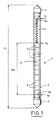
- Figure 1 is a sectional view through a vertical plane of a rod of a fuel assembly of a pressurized water nuclear reactor.
- Figure 2 is an elevational view of an eddy current device for implementing the method according to the invention.
- FIG. 2A is a schematic top view of FIG. 2.
- FIG. 3 is a schematic view of the length measuring chain associated with the device shown in FIG. 2.
- Figure 4 is a top view along 4 of Figure 5 of the eddy current probe of the measuring device shown in Figure 3, in contact with a peripheral fuel rod of a fuel assembly.
- Figure 5 is a side view along 5-5 of Figure 4.
- FIG. 6 is a view in axial section of the eddy current probe shown in FIGS. 4 and 5.
- FIGS. 7A, 7B and 7C represent graphic records obtained during the implementation of the measurement method according to the invention.
- the general reference 1 designates a pencil for a nuclear fuel assembly of a pressurized water nuclear reactor.
- the fuel rod 1 comprises a tubular sheath 2 in a zirconium alloy such as Zircaloy 4, having a diameter of the order of one centimeter and a length of the order of four meters.
- a zirconium alloy such as Zircaloy 4
- the proportions of the pencil have been greatly modified, the ratio of the diameter to the length of the pencil having been greatly increased.
- a first plug 3, or lower plug, is engaged in a first end portion of the sheath 2 whose plug 3 ensures the closure.
- the plug 3 has an internal part of the cylindrical-frustoconical sheath whose maximum diameter (diameter of the cylindrical part) is substantially equal to the internal diameter of the sheath, so that the plug is engaged practically without play in the part d 'lower end of the sheath.
- the part of the plug 3 disposed inside the sheath 2 ends in a flat surface 3a constituting the small base of the frustoconical end of the internal part of the plug 3.
- the sheath 2 contains a column 4 of nuclear fuel pellets 5 stacked one on the other in the axial direction of the sheath 2.
- the column 4 is shown as consisting of a relatively small number of pellets of combustible material.
- the sheath contains a very large number of pellets 5 stacked one on the other.
- the pellets 5 can for example be made of a fissile combustible material such as uranium oxide UO 2 enriched in uranium 235, obtained by sintering.
- a first end of the column of combustible material or fissile column 4 rests on the internal surface 3a of the lower plug 3.
- an upper plug 6 is introduced, the shape of which is substantially identical to the shape of the lower plug 3 and which comprises a cylindrical-frustoconical part engaged inside the sheath 2 terminated by a flat internal surface 6a substantially perpendicular to the axis of the sheath 2.
- the total length in the axial direction of the column 4 of pellets of fissile combustible material 5 is less than the length in the axial direction of the sheath between the internal surfaces 3a of the lower plug 3 and 6a of the upper plug 6.
- a helical spring 7 is interposed between the internal end 6a of the upper plug 6 and the upper end of the fissile column 4 opposite the end of the column resting on the internal surface 3a of the lower plug 3.
- the spring 7 which is compressed between the end 6a of the plug 6 and the upper end of the fissile column 4 ensures the maintenance of the fuel pellets inside the sheath 2 of the pencil 1.
- the fissile column 4 is produced by stacking the pellets of fissile combustible material, the base of the column resting on the internal surface 3a of the plug 3.
- the helical spring 7 and the plug are put in place. upper 6 and the plugs are welded to the sheath.
- the internal volume of the sheath 2 is evacuated and filled with inert gas from the upper plug 6 which is then closed in a sealed manner.
- the fissile fuel pellets 5 have a diameter smaller than the inside diameter of the cladding, so as to allow radial expansion of the pellets 5, during the swelling under irradiation of the pellets in the operating nuclear reactor.
- the rods which are engaged in the framework of the assembly may have undergone certain deteriorations which result in a deformation of the sheath 2 and in a modification of the shape and the length of the fissile column 4.
- the method and the device according to the invention make it possible to carry out such measurements in the deactivation pool, on the peripheral rods of the fuel assemblies discharged from the core and stored in the spent fuel pool.
- the measuring device generally designated by the reference 8 comprises an eddy current probe 10 carried by a handling assembly 9 which will be described below, itself resting on a carrier 11 which can be made integral with the cell 12 of a descender of the spent fuel pool of the nuclear reactor.
- the wall 13 of the pool comprises, at the interior of a housing 14 in withdrawal inside the wall 13 of the swimming pool, a descender 12 constituted by a cell capable of receiving a fuel assembly 15 and associated with means of displacement in the vertical direction inside the vertical housing 14 in the wall of the swimming pool, to ensure the descent of a fuel assembly 15 into the bottom of the swimming pool.
- the fuel assemblies can be taken care of by the handling bridge of the spent fuel pool to be deposited in fixed cells resting on the bottom of the spent fuel pool.
- the measuring device 8 is used in association with a descender of the spent fuel pool, the carrier 11 comprising means making it possible to clamp it on the upper part of the cell 12 of the descender of the pool of the spent fuel.
- the carrier 11 comprises a horizontal plate on which rests a displacement table 16 in two directions of the horizontal plane at 90 °.
- Table 16 or XY table supports a vertical guide column 17 on which is mounted movable in the vertical direction of the axis 18 a carriage 19 for moving the probe 10 in the vertical direction.
- the device which has just been described makes it possible to place the probe 10 opposite any pencil situated at the periphery of the assembly 15, such as the rods 1a, 1b or 1c shown in FIG. 2A, by moving the table XY 16 in its first direction of horizontal movement X.
- the second movement in the horizontal direction makes it possible to move the eddy current probe 10 perpendicular to a face of the fuel assembly 15 between a position in which the probe 10 comes into contact with a fuel rod 1 of assembly 15, as shown in Figure 2 and a withdrawal position in which the probe 10 is not in contact with a pencil of assembly, as shown in Figure 2A.
- Motor means 22 controlled remotely from the edge of the spent fuel pool make it possible to carry out the displacements in X and in Y of the measuring device 8 comprising the probe 10; the displacements in the vertical direction or displacements in the Z direction of the probe 10 are obtained very precisely and with a very low speed by using a motor means 21.
- the movements of the probe 10 in the vertical direction can also be carried out at high speed, the probe 10 being in its position of withdrawal away from the peripheral rods of the fuel assembly 5, by virtue of the descender 12 on which the carrier 11 is clamped on which is mounted the measuring device 8 and its displacement means.
- the high speed movement of the measuring assembly 8 using the descender makes it possible to place the probe 10 approximately opposite a measurement zone of a fuel rod of the assembly 15, such as the lower plug, the upper plug or the lower part of the fissile column retaining spring.
- the position in the direction Z of the probe 10 is determined very precisely using a mark 20 placed vertically along the wall of the fuel pool in an arrangement adjacent to the vertical housing 14 of the descender.
- the reference 20 is constituted by a flexible rule housed in a rewinder housing disposed at the upper level of the swimming pool, one end of which is fixed to the carriage 19 for Z-displacement of the eddy current probe 10, comprising graduations which can be read and counted by a coding device 25.
- the coding device 25 disposed at the upper level of the swimming pool provides an output signal with square slots, each of the slots of the encoder signal corresponding to a vertical distance of 0.1 mm. It is therefore possible to know the position of the probe with an accuracy of 0.1 mm.
- Two video cameras 23 and 24 are intended to provide, on the upper level of the swimming pool, on a screen an image of the end part of the probe 10 to verify its positioning in the service position on one of the peripheral tubes 1 of the assembly 15.
- the camera 23 makes it possible to give an image of the eddy current probe 10 from above and the camera 24 makes it possible to provide an image of the end of the probe 10 in a side view.
- the carrier 11 of the measuring device 8 and its means of displacement in X, Y and Z comprises a support belt comprising a square internal opening allowing the passage of a fuel assembly as well as lugs 26 for fixing the carrier 11 on the upper part of the cell 12 of the descender, the pins 26 being associated with operating devices that can be actuated from the upper part of the spent fuel pool.
- Two guide rollers 27a and 27b are mounted on the upper surface of the belt of the carrier 11, by means of pivoting supports so as to guide the movements of the carrier 11 relative to the substantially planar external faces of the assembly 15 with square section.
- the supports of the guide rollers 27a and 27b are pivotally mounted so as to allow the passage of the rollers at the grids 28 of the assembly 15 in which the rods of the assembly are engaged, thus maintained in a regular network.
- the eddy current probe 10 is mounted on a support fixed on the carriage 19 with vertical displacement and connected by means of a measurement cable 29 to a device for supplying electric current and for processing measurements arranged at the upper level of the pool.
- the cameras 23 and 24 as well as the displacement devices 21 and 22 are also connected to supply and control means arranged at the upper level of the swimming pool. It is therefore possible to remotely supply the probe, collect the measurement signals, view the end part of the probe and the pens under examination as well as control the movements of the probe in X , Y and Z.
- the rapid movements of the probe in the Z direction are controlled by the control means of the fuel pool descender.
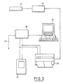
- FIG 3 there is shown schematically the measuring chain associated with the measuring device shown in Figure 2 and arranged at the upper level of the pool.
- the measuring chain comprises a unit 30 called an eddy current device bringing together the means for supplying the eddy current probe and for collecting measurement signals via the cable 29 as well as a unit 31 for viewing the signals from the eddy current probe and a graphical recorder 32 of these signals.
- the eddy current apparatus 30 has two output channels called channel X and channel Y connected in parallel to the display unit 31 and to the recorder 32.
- the measurement chain further comprises a display unit 33 connected to the altitude encoder 25 of the measurement device making it possible to display the altitude of the eddy current probe 10 within 0.1 mm. the spent fuel pool.
- a microcomputer 34 makes it possible to manage the entire measurement program and to record the results of the measurements on the various peripheral rods of the fuel assemblies on which the measurements of characteristic length are carried out.
- the control and measurement station located on the upper level of the swimming pool also includes display screens making it possible to provide the operator responsible for measurements with images of the end of the probe from video cameras 23 and 24.
- the eddy current probe 10 is shown, the end portion 10a of which constitutes the measuring head is placed in contact with a fuel rod 1 of the bundle of the nuclear fuel assembly 15 on which length measurements are made.
- the measuring head 10a of the eddy current probe 10 has a notched shape and a substantially cylindrical contact surface allowing perfect contact and coupling between the measuring head and the surface of the fuel rod cladding 1.
- the measuring head 102 can be made of zirconia ZrO 2 or zirconia.
- the measuring coil 35, 35 ', the measuring head 10a and the support 36 are mounted inside a movable support 37 mounted to slide in the axial direction 38 of the probe inside a main body of probe 39.
- the movable support 37 and the main body 39 of the probe are cylindrical in shape and have the axis 38 of the probe as a common axis.
- the main probe body 39 has a longitudinal groove 40 of axial direction in which is engaged a guide pin 41 secured to the movable support 37.
- the guide pin 41 is engaged with a certain play in the circumferential direction, inside the groove 40. In this way, the movable support 37 mounted to slide in the axial direction 38 on the probe body 39 can only pivot around the axis 38 in a limited manner.
- the measuring head 10a and in particular the end in the form of a cylindrical cavity thus keep an orientation with respect to the vertical rods 1 of the bundle of the nuclear fuel assembly allowing the cavity to be engaged on a pencil for carrying out the measurements, with a certain freedom of movement in rotation to adapt to the profile of the pencil.
- a pushing piece 42 comprising a cavity having a v-shaped section directed towards the measuring coil 35, 35 '.
- a reference standard tube 44 consisting of a portion of a fuel rod sheath similar to the fuel rod 1 is interposed between the pusher 42 and the support 36 of the end portion of the winding 35 'of the coil opposite the measuring head 10a.
- an annular abutment part 43 In the end part of the main body 39 of the probe 10 is screwed an annular abutment part 43.
- a helical spring 45 is interposed between the abutment part 43 and the thrust part 42.
- the helical spring 45 allows to authorize displacements of the movable support 37 and of the measuring head 10a of the probe 10 relative to the main body 39 integral with the probe support, both during docking and during the displacements of the probe 10 in the vertical direction.
- the spring 45 exerts a thrust on the movable support 37 and on the measuring head 10a so that the measuring head 10a is in perfect contact by its cylindrical end surface with the external surface of the sheath of the pencil 1 on which the measurements are made.
- This arrangement makes it possible to avoid exerting, by means of the probe, an excessive force on the sheath of the pencil and by means of the pencil on the springs for holding the pencil in the grid cells of the fuel assembly. This avoids any plastic deformation of the springs holding the rods of the assembly during the measurements carried out on the peripheral rods.
- the spring 45 is provided with a constant such that the force exerted on the measuring head by the compressed spring to the maximum, ie ie when the guide finger 41 has come into abutment in the bottom of the groove of the main body 39, that is to say a maximum of 25 N.
- the measuring head 10a has at its upper part and at its lower part two chamfered contact surfaces, inclined at 45 ° relative to the axis 38 of the probe.
- the inclined portions of the probe allow the probe to easily pass through the grids of the assembly whose peripheral belt is slightly projecting from the sheaths of the peripheral rods of the assembly.
- the crossing is achieved by bringing the chamfered surfaces of the measuring head 10a into contact with the peripheral belt of the spacer grid, in particular at the level of guide fins of the fuel assembly whose inclination is identical to the inclination of the chamfered parts of the measuring head 10a and by a displacement of the movable support 37 of the probe towards the rear accompanied by the compression of the spring 45.
- the measurement windings 35 and 35 ′ arranged in the axial extension of one another are typically supplied with alternating current during the measurements and moved in the vicinity of the external surface of the fuel rod on which the measurements are carried out.
- the variations in the eddy currents flowing in the fuel rod opposite the probe lead to variations in the impedance of the probe, which makes it possible to identify certain characteristic elements inside. of the pencil sheath as a function of the signal supplied by the eddy current probe.
- the characteristic signal can be obtained depending on the case, either on the output channel X or on the output channel Y of the eddy current apparatus.
- FIGS. 7A, 7B and 7C the characteristic signals obtained on channel X and on channel Y of the output of the eddy current apparatus are shown, opposite the scale graduated in the direction vertical giving the altitude of the probe to the nearest 0,1 mm.
- the signals shown in FIGS. 7A, 7B and 7C are obtained on the screen of the display unit 31 of the measurement chain.
- FIG. 7A the signals 50 and 51 from the outputs X and Y of the eddy current apparatus 30 are shown, when the probe 10 is facing the internal surface 3A of the lower plug 3 a fuel rod 1 as shown in FIG. 1.
- the signal 51 of channel Y of the eddy current apparatus has a very clear maximum which makes it possible to determine the altitude of the internal surface 3a constituting the lower end of the fissile column 4 extremely precisely.
- the output signals 52 and 53 are shown on the channels X and Y of the eddy current apparatus respectively, when the probe is opposite the lower end of the spring 7 of pencil 1 coming into contact with the upper end of the fissile column 4.
- the top of the signal 52 coming from channel X of the eddy current apparatus makes it possible to determine with very great precision the position of the lower end of the spring, that is to say the position of the upper end of the fissile column 4.
- FIG. 7C there are shown the signals 54 and 55 which are respectively the output signals of the channels X and Y of the eddy current apparatus, when the probe 10 is opposite the internal surface 6a of the upper plug 6 of the fuel rod 1.
- the top of the output signal 55 of the channel Y makes it possible to determine with very great precision the position of the internal surface 6a of the upper plug 6.
- the handling bridge of the spent fuel pool is used to take charge the fuel assembly and bring the fuel assembly into alignment with the axis of the cell 12 of the descender on the upper part of which the carrier of the measuring device is clamped as shown in FIG. 2.
- the fuel assembly is oriented so that one of its peripheral faces is directed perpendicular to the axis 28 of the probe mounted on the carriage 19 for vertical displacement of the measuring device 8. The fuel assembly is then maintained in this position by the handling device to which it is suspended.
- the probe is placed in a withdrawal position obtained by retraction of the movement carriage in the Y direction of the XY table 16.
- the axis of the probe 10 is placed opposite of a first peripheral fuel rod of the assembly 15 disposed at one end of the peripheral face directed towards the measurement probe.
- the measuring head 10a of the probe 10 is brought into contact with the external surface of the pencil sheath.
- the eddy current probe is supplied and the signals produced by the probe are identified during a very low speed movement in the vertical direction using the carriage 19 for movement in the Z direction.
- the carriage 19 for movement in the Z direction and its guide and displacement means are produced so as to obtain maximum displacement of the probe in the Z direction at a speed of the order of 1 mm / second, over a distance of 100 to 150 mm.
- the altitude Z B given by the altitude encoder is recorded.
- a withdrawal of the probe is then carried out relative to the guide tube by displacement in the direction Y of the probe, in order to move it away from the fuel rod.
- the descender is then used to move the measuring device 8 fixed on the carrier 11 secured to the cell 12 in the vertical direction until the eddy current probe has reached an altitude position which is close to the theoretical position in altitude of the top of the fissile column 4.
- the location of the signal 52 representative of the lower part of the spring makes it possible to determine the altitude Z R.
- the probe is then replaced in the withdrawn position and the entire measuring device is moved to the vicinity of the upper part of the pencil to determine the altitude Z H of the internal surface 6a of the upper plug 6.
- the process according to the invention therefore makes it possible to quickly and extremely precisely obtain lengths characteristic of the peripheral fuel rods of irradiated fuel assemblies stored in the spent fuel pool of a nuclear reactor.
- the displacements of the measuring device along the length of the pencil and the positioning of the probe relative to the pencils on which measurements are made can be obtained using devices other than an XY cross-motion table and a carriage displacement in the vertical direction Z.
- the rapid displacements of the measuring device along the length of the rods of the assembly can be obtained by a device different from a descender of the fuel assembly.
- the eddy current probe may have a structure different from that which has been described.
- the invention can be applied to length measurements on peripheral rods for nuclear fuel assembly of a different type from the nuclear fuel assemblies usually used in pressurized water nuclear reactors.
Landscapes
- Physics & Mathematics (AREA)
- Engineering & Computer Science (AREA)
- General Physics & Mathematics (AREA)
- Plasma & Fusion (AREA)
- General Engineering & Computer Science (AREA)
- High Energy & Nuclear Physics (AREA)
- Monitoring And Testing Of Nuclear Reactors (AREA)
- Measurement Of Length, Angles, Or The Like Using Electric Or Magnetic Means (AREA)
Applications Claiming Priority (2)
| Application Number | Priority Date | Filing Date | Title |
|---|---|---|---|
| FR9511333A FR2739180B1 (fr) | 1995-09-27 | 1995-09-27 | Procede et dispositif de mesure d'au moins une longeur caracteristique sur un crayon de combustible dispose a la peripherie d'un assemblage de combustible nucleaire |
| FR9511333 | 1995-09-27 |
Publications (3)
| Publication Number | Publication Date |
|---|---|
| EP0766265A2 true EP0766265A2 (de) | 1997-04-02 |
| EP0766265A3 EP0766265A3 (de) | 1997-04-09 |
| EP0766265B1 EP0766265B1 (de) | 1999-03-10 |
Family
ID=9482969
Family Applications (1)
| Application Number | Title | Priority Date | Filing Date |
|---|---|---|---|
| EP96401925A Expired - Lifetime EP0766265B1 (de) | 1995-09-27 | 1996-09-09 | Verfahren und Vorrichtung zum Messen mindestens einer charakterisierenden Länge eines Brennstabs an der Peripherie eines Kernbrennstabbündels |
Country Status (5)
| Country | Link |
|---|---|
| US (1) | US5754611A (de) |
| EP (1) | EP0766265B1 (de) |
| DE (1) | DE69601683T2 (de) |
| ES (1) | ES2128151T3 (de) |
| FR (1) | FR2739180B1 (de) |
Cited By (4)
| Publication number | Priority date | Publication date | Assignee | Title |
|---|---|---|---|---|
| CN109346201A (zh) * | 2018-11-22 | 2019-02-15 | 河北工业大学 | 一种基于等效容积测量的核燃料组件内部变形检测装置 |
| CN109360670A (zh) * | 2018-12-03 | 2019-02-19 | 河北工业大学 | 一种自适应对中核燃料组件多功能检测装置 |
| CN109373885A (zh) * | 2018-12-21 | 2019-02-22 | 河北工业大学 | 一种基于阵列式柔性检测的核燃料组件多功能检测装置 |
| CN113436765A (zh) * | 2021-06-23 | 2021-09-24 | 中核武汉核电运行技术股份有限公司 | 一种核反应堆燃料组件燃料单棒涡流、视频集成检验装置 |
Families Citing this family (14)
| Publication number | Priority date | Publication date | Assignee | Title |
|---|---|---|---|---|
| US5978430A (en) * | 1998-10-06 | 1999-11-02 | General Electric Company | Length gauge for in situ measurement of water rod lengths in nuclear fuel bundles and methods of measurement |
| FR2808372B1 (fr) * | 2000-04-27 | 2002-07-26 | Framatome Sa | Procede et dispositif de mesure du diametre d'un crayon peripherique d'un assemblage de combustible d'un reacteur nucleaire |
| DE10123975A1 (de) * | 2001-05-17 | 2002-12-05 | Framatome Anp Gmbh | Meßkopf, insbesondere zum Einsatz bei der Vermessung eines Brennstabs, eines Brennelementkastens und/oder eines Abstandshalters oder sonstige Strukturteile in einem Brennelement einer kerntechnischen Anlage |
| US6895066B1 (en) | 2001-05-17 | 2005-05-17 | Framatome Anp Gmbh | Measuring head and measuring assembly for a nuclear fuel rod |
| KR100470932B1 (ko) * | 2002-07-31 | 2005-02-21 | 한국수력원자력 주식회사 | 와전류 탐상검사용 핵연료봉 이송장치 |
| WO2008129969A1 (ja) * | 2007-04-13 | 2008-10-30 | Kabushiki Kaisha Toshiba | 燃焼度相対分布測定方法、燃焼度相対分布測定装置、放射線信号分布測定装置及び燃焼度相対分布測定プログラム |
| US8428215B2 (en) * | 2007-12-20 | 2013-04-23 | Westinghouse Electric Company Llc | Method of improving the spent nuclear fuel burnup credit |
| US9697916B2 (en) | 2008-01-09 | 2017-07-04 | Analysis And Measurement Corporation | Automated system for on-line monitoring and diagnostics of rod position indication coils for nuclear power plants |
| ES2350997B1 (es) * | 2009-06-08 | 2011-11-23 | Enusa Industrias Avanzadas S.A. | Aparato para la inspeccion radiometrica de un elemento combustible |
| KR101222012B1 (ko) * | 2011-07-08 | 2013-01-14 | 한전원자력연료 주식회사 | 핵연료집합체의 핵연료봉 외경 측정장치 |
| KR101200781B1 (ko) * | 2011-07-08 | 2012-11-13 | 한전원자력연료 주식회사 | 프로브 및 이를 포함하는 연료봉 산화막 두께 측정장치 |
| KR101349135B1 (ko) * | 2012-01-04 | 2014-01-09 | 한전원자력연료 주식회사 | 핵연료봉 제조용 소결체 자동적재장치 |
| JP2014006050A (ja) * | 2012-06-21 | 2014-01-16 | Aisan Ind Co Ltd | 燃料特性計測装置 |
| WO2017122080A1 (en) * | 2016-01-12 | 2017-07-20 | Candu Energy Inc. | Torsional testing apparatus and method |
Family Cites Families (7)
| Publication number | Priority date | Publication date | Assignee | Title |
|---|---|---|---|---|
| US3967382A (en) * | 1975-01-10 | 1976-07-06 | Exxon Nuclear Company, Inc. | Plenum chamber length measurement system for nuclear fuel |
| US4195411A (en) * | 1978-04-25 | 1980-04-01 | Westinghouse Electric Corp. | Remote gaging apparatus |
| DE3107372C2 (de) * | 1981-02-27 | 1985-09-05 | Ntg Nukleartechnik Gmbh U. Partner, 6460 Gelnhausen | Brennelementkastenkontrollvorrichtung |
| FR2585869B1 (fr) * | 1985-08-01 | 1987-11-13 | Fragema Framatome & Cogema | Procede et dispositif de controle des crayons de grappe pour assemblage de combustible nucleaire. |
| US4728483A (en) * | 1986-04-24 | 1988-03-01 | Westinghouse Electric Corp. | Apparatus for integrated fuel assembly inspection system |
| JPS6319504A (ja) * | 1986-07-11 | 1988-01-27 | Mitsubishi Nuclear Fuel Co Ltd | 核燃料棒のプレナム長測定装置 |
| JPH07119563B2 (ja) * | 1986-07-11 | 1995-12-20 | 三菱原子燃料株式会社 | 核燃料棒のプレナム長測定装置 |
-
1995
- 1995-09-27 FR FR9511333A patent/FR2739180B1/fr not_active Expired - Fee Related
-
1996
- 1996-09-09 ES ES96401925T patent/ES2128151T3/es not_active Expired - Lifetime
- 1996-09-09 DE DE69601683T patent/DE69601683T2/de not_active Expired - Fee Related
- 1996-09-09 EP EP96401925A patent/EP0766265B1/de not_active Expired - Lifetime
- 1996-09-27 US US08/722,764 patent/US5754611A/en not_active Expired - Fee Related
Cited By (6)
| Publication number | Priority date | Publication date | Assignee | Title |
|---|---|---|---|---|
| CN109346201A (zh) * | 2018-11-22 | 2019-02-15 | 河北工业大学 | 一种基于等效容积测量的核燃料组件内部变形检测装置 |
| CN109346201B (zh) * | 2018-11-22 | 2019-11-19 | 河北工业大学 | 一种基于等效容积测量的核燃料组件内部变形检测装置 |
| CN109360670A (zh) * | 2018-12-03 | 2019-02-19 | 河北工业大学 | 一种自适应对中核燃料组件多功能检测装置 |
| CN109360670B (zh) * | 2018-12-03 | 2020-06-09 | 河北工业大学 | 一种自适应对中核燃料组件多功能检测装置 |
| CN109373885A (zh) * | 2018-12-21 | 2019-02-22 | 河北工业大学 | 一种基于阵列式柔性检测的核燃料组件多功能检测装置 |
| CN113436765A (zh) * | 2021-06-23 | 2021-09-24 | 中核武汉核电运行技术股份有限公司 | 一种核反应堆燃料组件燃料单棒涡流、视频集成检验装置 |
Also Published As
| Publication number | Publication date |
|---|---|
| US5754611A (en) | 1998-05-19 |
| EP0766265B1 (de) | 1999-03-10 |
| ES2128151T3 (es) | 1999-05-01 |
| EP0766265A3 (de) | 1997-04-09 |
| DE69601683T2 (de) | 1999-07-15 |
| DE69601683D1 (de) | 1999-04-15 |
| FR2739180A1 (fr) | 1997-03-28 |
| FR2739180B1 (fr) | 1998-09-04 |
Similar Documents
| Publication | Publication Date | Title |
|---|---|---|
| EP0766265B1 (de) | Verfahren und Vorrichtung zum Messen mindestens einer charakterisierenden Länge eines Brennstabs an der Peripherie eines Kernbrennstabbündels | |
| EP1277212B1 (de) | Verfahren und vorrichtung zum messen des durchmessers eines randbrennstabs als teil eines kernreaktorbrennstabbündels | |
| EP0213028B1 (de) | Verfahren und Vorrichtung zur Überprüfung von Stäben eines Stabkreuzes für ein Kernbrennstabbündel | |
| BE1000315A3 (fr) | Appareil pour systeme integre d'inspection d'assemblages combustibles. | |
| EP0123597B1 (de) | Prüfstände für Reaktorbrennelemente | |
| EP0080418A1 (de) | Verfahren und Einrichtung zur Prüfung eines Brennelementbündels eines Kernreaktors | |
| EP2208206B1 (de) | Einrichtung zur untersuchung einer brennstabbaugruppe im pool einer kernanlage und entsprechendes untersuchungsverfahren | |
| EP0655747B1 (de) | Vorrichtung und Verfahren zum Überprüfen der Führungselemente eines Führungsrohrs in den oberen Einbauten eines Druckwasserkernreaktors | |
| EP0390637B1 (de) | Verfahren und Vorrichtung zur Dimensions- und Geometrieüberprüfung von Führungs- und Positionierungselementen in den oberen Einbauten eines Druckwasser-Kernreaktors | |
| FR2818736A1 (fr) | Procede et dispositif de mesure de l'epaisseur d'une couche d'oxyde sur la gaine de crayons dans un assemblage de combustible | |
| WO2010037948A1 (fr) | Procede d'evaluation de grandeurs relatives a la deformation d'un assemblage de combustible nucleaire | |
| EP1733205B1 (de) | Verfahren und system zur bestimmung von massedichte und abmessungsmerkmalen eines gegenstands sowie dessen verwendung zur überwachung von kernbrennstoffpellets während deren herstellung | |
| FR2754053A1 (fr) | Procede et dispositif de mesure de deformation de tube guide | |
| FR2752639A1 (fr) | Dispositif de caracterisation individuelle d'assemblages de combustible nucleaire et installation de controle non destructif comprenant un tel dispositif | |
| FR2931580A1 (fr) | Mesure de la pression interne de crayons combustibles | |
| FR2857152A1 (fr) | Dispositif et procede de controle d'aspect exterieur de crayons de combustible pour reacteur nucleaire | |
| JPH1039085A (ja) | 燃料の燃焼度モニタ方法および簡易型燃焼度モニタ | |
| FR2817338A1 (fr) | Procede et dispositif de mesure de l'epaisseur d'une couche d'oxyde sur la surface laterale externe d'un crayon de combustible | |
| EP0329554B1 (de) | Verfahren und Einrichtung zum Auffinden undichter Stäbe in einer Kernbrennelementanordnung | |
| FR2642560A1 (fr) | Procede et dispositif de detection par ultrasons de crayons combustibles non etanches dans un assemblage combustible | |
| WO2006070091A1 (fr) | Procede et dispositif de determination du taux de combustion d'un assemblage de combustible du coeur d'un reacteur nucleaire et utilisation | |
| EP2442313B1 (de) | Vorrichtung zur radiometrischen prüfung von brennstoffelementen | |
| FR2696578A1 (fr) | Dispositif et procédé de mesure de l'inclinaison d'un pion de centrage d'un assemblage combustible. | |
| EP3273445B1 (de) | Vorrichtung zum operieren mit kernbrennstoffelementen | |
| WO1998011559A1 (fr) | Procede pour determiner l'etat d'un assemblage de combustibles nucleaires et dispositif mettant en oeuvre ce procede |
Legal Events
| Date | Code | Title | Description |
|---|---|---|---|
| PUAI | Public reference made under article 153(3) epc to a published international application that has entered the european phase |
Free format text: ORIGINAL CODE: 0009012 |
|
| PUAL | Search report despatched |
Free format text: ORIGINAL CODE: 0009013 |
|
| AK | Designated contracting states |
Kind code of ref document: A2 Designated state(s): BE DE ES FR GB |
|
| AK | Designated contracting states |
Kind code of ref document: A3 Designated state(s): BE DE ES FR GB |
|
| 17P | Request for examination filed |
Effective date: 19970315 |
|
| GRAG | Despatch of communication of intention to grant |
Free format text: ORIGINAL CODE: EPIDOS AGRA |
|
| 17Q | First examination report despatched |
Effective date: 19980716 |
|
| GRAG | Despatch of communication of intention to grant |
Free format text: ORIGINAL CODE: EPIDOS AGRA |
|
| GRAH | Despatch of communication of intention to grant a patent |
Free format text: ORIGINAL CODE: EPIDOS IGRA |
|
| GRAH | Despatch of communication of intention to grant a patent |
Free format text: ORIGINAL CODE: EPIDOS IGRA |
|
| GRAA | (expected) grant |
Free format text: ORIGINAL CODE: 0009210 |
|
| AK | Designated contracting states |
Kind code of ref document: B1 Designated state(s): BE DE ES FR GB |
|
| GBT | Gb: translation of ep patent filed (gb section 77(6)(a)/1977) |
Effective date: 19990315 |
|
| REF | Corresponds to: |
Ref document number: 69601683 Country of ref document: DE Date of ref document: 19990415 |
|
| REG | Reference to a national code |
Ref country code: ES Ref legal event code: FG2A Ref document number: 2128151 Country of ref document: ES Kind code of ref document: T3 |
|
| PLBE | No opposition filed within time limit |
Free format text: ORIGINAL CODE: 0009261 |
|
| STAA | Information on the status of an ep patent application or granted ep patent |
Free format text: STATUS: NO OPPOSITION FILED WITHIN TIME LIMIT |
|
| 26N | No opposition filed | ||
| REG | Reference to a national code |
Ref country code: FR Ref legal event code: TQ |
|
| REG | Reference to a national code |
Ref country code: GB Ref legal event code: 732E |
|
| PGFP | Annual fee paid to national office [announced via postgrant information from national office to epo] |
Ref country code: DE Payment date: 20010821 Year of fee payment: 6 |
|
| PGFP | Annual fee paid to national office [announced via postgrant information from national office to epo] |
Ref country code: ES Payment date: 20010830 Year of fee payment: 6 |
|
| PGFP | Annual fee paid to national office [announced via postgrant information from national office to epo] |
Ref country code: GB Payment date: 20010904 Year of fee payment: 6 |
|
| PGFP | Annual fee paid to national office [announced via postgrant information from national office to epo] |
Ref country code: BE Payment date: 20011003 Year of fee payment: 6 |
|
| REG | Reference to a national code |
Ref country code: GB Ref legal event code: IF02 |
|
| REG | Reference to a national code |
Ref country code: FR Ref legal event code: TP |
|
| PG25 | Lapsed in a contracting state [announced via postgrant information from national office to epo] |
Ref country code: GB Free format text: LAPSE BECAUSE OF NON-PAYMENT OF DUE FEES Effective date: 20020909 |
|
| PG25 | Lapsed in a contracting state [announced via postgrant information from national office to epo] |
Ref country code: ES Free format text: LAPSE BECAUSE OF NON-PAYMENT OF DUE FEES Effective date: 20020910 |
|
| PG25 | Lapsed in a contracting state [announced via postgrant information from national office to epo] |
Ref country code: BE Free format text: LAPSE BECAUSE OF NON-PAYMENT OF DUE FEES Effective date: 20020930 |
|
| BERE | Be: lapsed |
Owner name: *FRAMATOME ANP Effective date: 20020930 |
|
| PG25 | Lapsed in a contracting state [announced via postgrant information from national office to epo] |
Ref country code: DE Free format text: LAPSE BECAUSE OF NON-PAYMENT OF DUE FEES Effective date: 20030401 |
|
| GBPC | Gb: european patent ceased through non-payment of renewal fee |
Effective date: 20020909 |
|
| REG | Reference to a national code |
Ref country code: ES Ref legal event code: FD2A Effective date: 20031011 |
|
| REG | Reference to a national code |
Ref country code: FR Ref legal event code: CD Ref country code: FR Ref legal event code: CA |
|
| PGFP | Annual fee paid to national office [announced via postgrant information from national office to epo] |
Ref country code: FR Payment date: 20111004 Year of fee payment: 16 |
|
| REG | Reference to a national code |
Ref country code: FR Ref legal event code: ST Effective date: 20130531 |
|
| PG25 | Lapsed in a contracting state [announced via postgrant information from national office to epo] |
Ref country code: FR Free format text: LAPSE BECAUSE OF NON-PAYMENT OF DUE FEES Effective date: 20121001 |