EP0435390B1 - Redresseur de demi-pont, insensible à des courants de mode commun - Google Patents
Redresseur de demi-pont, insensible à des courants de mode commun Download PDFInfo
- Publication number
- EP0435390B1 EP0435390B1 EP90203379A EP90203379A EP0435390B1 EP 0435390 B1 EP0435390 B1 EP 0435390B1 EP 90203379 A EP90203379 A EP 90203379A EP 90203379 A EP90203379 A EP 90203379A EP 0435390 B1 EP0435390 B1 EP 0435390B1
- Authority
- EP
- European Patent Office
- Prior art keywords
- high side
- sense resistors
- transistor
- lines
- voltage
- Prior art date
- Legal status (The legal status is an assumption and is not a legal conclusion. Google has not performed a legal analysis and makes no representation as to the accuracy of the status listed.)
- Expired - Lifetime
Links
Images
Classifications
-
- H—ELECTRICITY
- H02—GENERATION; CONVERSION OR DISTRIBUTION OF ELECTRIC POWER
- H02M—APPARATUS FOR CONVERSION BETWEEN AC AND AC, BETWEEN AC AND DC, OR BETWEEN DC AND DC, AND FOR USE WITH MAINS OR SIMILAR POWER SUPPLY SYSTEMS; CONVERSION OF DC OR AC INPUT POWER INTO SURGE OUTPUT POWER; CONTROL OR REGULATION THEREOF
- H02M7/00—Conversion of ac power input into dc power output; Conversion of dc power input into ac power output
- H02M7/42—Conversion of dc power input into ac power output without possibility of reversal
- H02M7/44—Conversion of dc power input into ac power output without possibility of reversal by static converters
- H02M7/48—Conversion of dc power input into ac power output without possibility of reversal by static converters using discharge tubes with control electrode or semiconductor devices with control electrode
- H02M7/505—Conversion of dc power input into ac power output without possibility of reversal by static converters using discharge tubes with control electrode or semiconductor devices with control electrode using devices of a thyratron or thyristor type requiring extinguishing means
- H02M7/515—Conversion of dc power input into ac power output without possibility of reversal by static converters using discharge tubes with control electrode or semiconductor devices with control electrode using devices of a thyratron or thyristor type requiring extinguishing means using semiconductor devices only
- H02M7/519—Conversion of dc power input into ac power output without possibility of reversal by static converters using discharge tubes with control electrode or semiconductor devices with control electrode using devices of a thyratron or thyristor type requiring extinguishing means using semiconductor devices only in a push-pull configuration
-
- H—ELECTRICITY
- H01—ELECTRIC ELEMENTS
- H01L—SEMICONDUCTOR DEVICES NOT COVERED BY CLASS H10
- H01L2924/00—Indexing scheme for arrangements or methods for connecting or disconnecting semiconductor or solid-state bodies as covered by H01L24/00
- H01L2924/0001—Technical content checked by a classifier
- H01L2924/0002—Not covered by any one of groups H01L24/00, H01L24/00 and H01L2224/00
Landscapes
- Engineering & Computer Science (AREA)
- Power Engineering (AREA)
- Electronic Switches (AREA)
- Dc-Dc Converters (AREA)
- Power Conversion In General (AREA)
- Inverter Devices (AREA)
Claims (7)
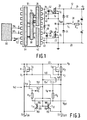
- Dispositif de commande réglable d'un demi-pont (12) comprenant un moyen de commutation amont (TH) et un moyen de commutation aval (TG), ledit moyen de commutation amont étant couplé à la sortie du demi-pont et ayant une entrée de commande, ledit dispositif contenant un redresseur amont comprenant :
une sortie de redresseur amont destinée à être couplée à l'entrée de commande dudit moyen de commutation amont, de façon à placer sélectivement ledit moyen de commutation amont dans l'état EN SERVICE ou dans l'état HORS SERVICE; des moyens pour recevoir sur deux lignes (70, 72) des courants de commande amont, caractérisé en ce que chaque ligne a ses propres résistances de détection, branchées en série avec chaque dite ligne et
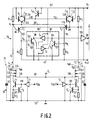
des moyens différentiels (T₁, T₂, R₅, R₆), couplés entre lesdites résistances de détection et ladite sortie de commande amont (VD), pour commander l'état du moyen de commutation amont en réponse à la différence entre les tensions (V₁, V₂) auxdites résistances de détection, en appréhendant si elles se trouvent dans les limites d'une plage dynamique opérationnelle. - Dispositif selon la revendication 1, caractérisé en ce que ledit moyen différentiel comprend un moyen amplificateur différentiel comportant deux entrées (88, 84), couplées respectivement aux résistances de détection desdites deux lignes et ayant deux sorties d'amplificateur (92, 94), de polarité inverse; un dispositif d'état (96) ayant une entrée ETABLISSEMENT couplée à l'une desdites sorties d'amplificateur, une entrée REMISE A L'ETAT INITIAL couplée à l'autre desdites sorties d'amplificateur et une sortie (104) couplée à ladite sortie de commande amont.
- Dispositif selon la revendication 1 ou 2, caractérisé en ce que ledit moyen différentiel comporte une zone morte au centre de sa plage dynamique opérationnelle, les valeurs ohmiques desdites résistances de détection et la largeur de ladite zone morte étant choisies de façon à donner audit moyen différentiel une insensibilité opérationnelle notable aux courants de bruit passant dans lesdites lignes, tout en donnant une réponse opérationnelle notable auxdits courants de commande.
- Dispositif selon la revendication 1, 2 ou 3, caractérisé en ce que ledit organe de commande amont comprend, en outre, un moyen pour recevoir une alimentation de tension à autoélevation (VB), avec une base flottante sur la sortie du demi-pont, et des moyens de fixation de niveau (T₉ à T₁₃) pour limiter les tensions sur les lignes par rapport à la base d'alimentation de tension d'autoélévation de niveau.
- Dispositif selon la revendication 4, caractérisé en ce que ledit moyen de fixation de niveau comprend au moins deux jonctions PN (T₉, T₁₀) parasites.
- Dispositif selon l'une quelconques des revendications 1 à 5, caractérisé en ce que les résistances de détection sont choisies avec des valeurs ohmiques suffisamment faibles, de manière que les tensions sur lesdites résistances de détection, imputables auxdits courants de mode commun et auxdits courants de commande, lorsqu'elles se manifestent simultanément, ne sortent pratiquement de la plage dynamique opérationnelle dudit moyen amplificateur différentiel.
- Dispositif selon l'une quelconque des revendications 1 à 6, caractérisé en ce qu'il comprend, en outre, un moyen pour transmettre lesdits courants de commande dans lesdites lignes, comprenant des moyens d'ajustement des amplitudes desdits courants de commande, basés sur des éléments (T₃, T₄; R₃, R₄) situés dans ledit moyen de transmission et adaptés aux éléments (T₁, T₂; R₁, R₂) situés dans ledit organe de commande amont, pour donner une mesure des valeurs ohmiques desdites résistances de détection et de la largeur de ladite zone morte.
Applications Claiming Priority (2)
| Application Number | Priority Date | Filing Date | Title |
|---|---|---|---|
| US07/459,095 US4994955A (en) | 1989-12-29 | 1989-12-29 | Half-bridge driver which is insensitive to common mode currents |
| US459095 | 1989-12-29 |
Publications (3)
| Publication Number | Publication Date |
|---|---|
| EP0435390A2 EP0435390A2 (fr) | 1991-07-03 |
| EP0435390A3 EP0435390A3 (en) | 1993-02-24 |
| EP0435390B1 true EP0435390B1 (fr) | 1995-03-15 |
Family
ID=23823384
Family Applications (1)
| Application Number | Title | Priority Date | Filing Date |
|---|---|---|---|
| EP90203379A Expired - Lifetime EP0435390B1 (fr) | 1989-12-29 | 1990-12-18 | Redresseur de demi-pont, insensible à des courants de mode commun |
Country Status (4)
| Country | Link |
|---|---|
| US (1) | US4994955A (fr) |
| EP (1) | EP0435390B1 (fr) |
| JP (1) | JP3037760B2 (fr) |
| DE (1) | DE69017869T2 (fr) |
Families Citing this family (32)
| Publication number | Priority date | Publication date | Assignee | Title |
|---|---|---|---|---|
| JP2634306B2 (ja) * | 1990-08-08 | 1997-07-23 | 三菱電機株式会社 | インバータ装置の駆動回路 |
| DE4237843A1 (de) * | 1992-11-10 | 1994-05-11 | Philips Patentverwaltung | Schaltungsanordnung zum Betreiben einer induktiven Last |
| DE69304189T2 (de) * | 1993-01-29 | 1997-01-23 | Sgs Thomson Microelectronics | Treiberschaltung für einen Feldeffekttransistor in einer Halbbrückenausgangsstufe |
| GB9302942D0 (en) * | 1993-02-13 | 1993-03-31 | Attwood Brian E | Low cost,low current power supply |
| US5373435A (en) * | 1993-05-07 | 1994-12-13 | Philips Electronics North America Corporation | High voltage integrated circuit driver for half-bridge circuit employing a bootstrap diode emulator |
| US5545955A (en) * | 1994-03-04 | 1996-08-13 | International Rectifier Corporation | MOS gate driver for ballast circuits |
| JP2896342B2 (ja) * | 1995-05-04 | 1999-05-31 | インターナショナル・レクチファイヤー・コーポレーション | 半波ブリッジ構成における複数のパワートランジスタを駆動し、かつ出力ノードの過度の負の振動を許容する方法及び回路、並びに上記回路を組み込む集積回路 |
| US5808883A (en) * | 1996-02-15 | 1998-09-15 | Harris Corporation | DC-to-DC converter having charge pump and associated methods |
| US5821740A (en) * | 1996-02-15 | 1998-10-13 | Harris Corporation | DC-to-DC converter having fast over-current detection and associated methods |
| US5793193A (en) * | 1996-02-15 | 1998-08-11 | Harris Corporation | DC-to-DC converter having enhanced control features and associated methods |
| JP3970960B2 (ja) * | 1996-07-18 | 2007-09-05 | 矢崎総業株式会社 | 半導体装置 |
| KR100308354B1 (ko) * | 1997-03-18 | 2001-11-30 | 다니구찌 이찌로오, 기타오카 다카시 | 전력변환장치 |
| US5903142A (en) * | 1997-06-27 | 1999-05-11 | Cypress Semiconductor Corp. | Low distortion level shifter |
| US6037720A (en) * | 1998-10-23 | 2000-03-14 | Philips Electronics North America Corporation | Level shifter |
| US6301135B1 (en) | 1999-03-01 | 2001-10-09 | Texas Instruments Incorporated | Isolated switching-mode power supply control circuit having secondary-side controller and supervisory primary-side controller |
| US6362679B2 (en) | 2000-02-23 | 2002-03-26 | Tripath Technology, Inc. | Power device driver circuit |
| SE0104400D0 (sv) | 2001-12-21 | 2001-12-21 | Bang & Olufsen Powerhouse As | Half-bridge driver and power conversion system with such driver |
| JP3794481B2 (ja) * | 2002-03-14 | 2006-07-05 | 富士電機デバイステクノロジー株式会社 | 負荷駆動回路および負荷駆動回路を有する半導体装置 |
| US7459750B2 (en) * | 2002-12-10 | 2008-12-02 | Nxp B.V. | Integrated half-bridge power circuit |
| US7301370B1 (en) * | 2003-05-22 | 2007-11-27 | Cypress Semiconductor Corporation | High-speed differential logic to CMOS translator architecture with low data-dependent jitter and duty cycle distortion |
| ES2223280B2 (es) * | 2003-07-14 | 2005-11-01 | Electronica De Balastos,S.L. | Sistema de manejo de la parte alta (hsd) de un dispositivo semipuente o puente para un circuito electronico de conmutacion. |
| WO2007003967A2 (fr) * | 2005-07-06 | 2007-01-11 | Cambridge Semiconductor Limited | Systemes de commande pour alimentation en mode commute |
| GB2433363A (en) * | 2005-12-16 | 2007-06-20 | Cambridge Semiconductor Ltd | A high side transistor drive circuit |
| US7710098B2 (en) * | 2005-12-16 | 2010-05-04 | Cambridge Semiconductor Limited | Power supply driver circuit |
| GB0615029D0 (en) * | 2005-12-22 | 2006-09-06 | Cambridge Semiconductor Ltd | Switch mode power supply controllers |
| US7733098B2 (en) * | 2005-12-22 | 2010-06-08 | Cambridge Semiconductor Limited | Saturation detection circuits |
| WO2008101548A1 (fr) * | 2007-02-22 | 2008-08-28 | Mueta B.V. | Circuit de décalage de niveau |
| WO2016101209A1 (fr) * | 2014-12-25 | 2016-06-30 | Texas Instruments Incorporated | Dispositif de commande de détection de courant pour convertisseur c.c.-c.c. |
| US9812962B2 (en) * | 2015-09-30 | 2017-11-07 | Intersil Americas LLC | Method and system for increasing efficiency and controlling slew rate in DC-DC converters |
| DE102017106188B3 (de) | 2017-03-22 | 2018-09-27 | Epcos Ag | Treiberschaltung zur Auswertung und Ansteuerung eines piezoelektrischen Bauelements, Taste mit haptischer Rückmeldung und Betriebsverfahren |
| EP3723287A1 (fr) | 2019-04-11 | 2020-10-14 | Koninklijke Philips N.V. | Circuit d'attaque de transducteur à ultrasons |
| EP3723286A1 (fr) | 2019-04-11 | 2020-10-14 | Koninklijke Philips N.V. | Circuit d'attaque en demi-pont de transducteur à ultrasons |
Family Cites Families (3)
| Publication number | Priority date | Publication date | Assignee | Title |
|---|---|---|---|---|
| US4706180A (en) * | 1985-11-29 | 1987-11-10 | York International Corporation | Pulse width modulated inverter system for driving single phase a-c induction motor |
| US4694384A (en) * | 1986-12-04 | 1987-09-15 | General Electric Company | HVIC power supply controller with primary-side edge detector |
| US4864479A (en) * | 1988-03-07 | 1989-09-05 | General Electric Company | Full-bridge lossless switching converter |
-
1989
- 1989-12-29 US US07/459,095 patent/US4994955A/en not_active Expired - Lifetime
-
1990
- 1990-12-18 DE DE69017869T patent/DE69017869T2/de not_active Expired - Fee Related
- 1990-12-18 EP EP90203379A patent/EP0435390B1/fr not_active Expired - Lifetime
- 1990-12-28 JP JP2418082A patent/JP3037760B2/ja not_active Expired - Fee Related
Also Published As
| Publication number | Publication date |
|---|---|
| DE69017869T2 (de) | 1995-10-12 |
| DE69017869D1 (de) | 1995-04-20 |
| EP0435390A2 (fr) | 1991-07-03 |
| JPH04138077A (ja) | 1992-05-12 |
| EP0435390A3 (en) | 1993-02-24 |
| US4994955A (en) | 1991-02-19 |
| JP3037760B2 (ja) | 2000-05-08 |
Similar Documents
| Publication | Publication Date | Title |
|---|---|---|
| EP0435390B1 (fr) | Redresseur de demi-pont, insensible à des courants de mode commun | |
| EP0649579B1 (fr) | Circuit de commande d'un demi-pont | |
| EP0812488B1 (fr) | Circuit de commande integre pour circuit en demi-pont | |
| US5742193A (en) | Driver circuit including preslewing circuit for improved slew rate control | |
| US7323912B2 (en) | Half-bridge driver and power conversion system with such driver | |
| US4758941A (en) | MOSFET fullbridge switching regulator having transformer coupled MOSFET drive circuit | |
| US5296765A (en) | Driver circuit for sinking current to two supply voltages | |
| GB2291294A (en) | Reset dominant level-shift high side MOS driver | |
| US7449841B2 (en) | Charge limited high voltage switch circuits | |
| EP0719475A1 (fr) | Circuit d'attaque pour circuit en pont utilisant un emulateur de diode d'amor age | |
| EP0735676B1 (fr) | Circuit d'attaque pour commutation à faible bruit de forts courants dans une charge | |
| JPS63304715A (ja) | Mosトランジスタブリッジを制御するための回路と方法 | |
| CN112019001B (zh) | 高侧晶体管的驱动电路、开关电路、控制器 | |
| US11451130B2 (en) | Circuit to transfer a signal between different voltage domains and corresponding method to transfer a signal | |
| JP2763237B2 (ja) | レベルシフト回路及びこれを用いたインバータ装置 | |
| US5381044A (en) | Bootstrap circuit for driving a power MOS transistor | |
| US11881759B2 (en) | Circuit to transfer a signal between different voltage domains and corresponding method to transfer a signal | |
| US5565715A (en) | Method and apparatus for logic signal level translation to a semiconductor switch | |
| EP0608667B1 (fr) | Circuit de commande pour un transistor à effet de champ dans un étage de sortie en demipont | |
| US6130569A (en) | Method and apparatus for a controlled transition rate driver | |
| JP2005020392A (ja) | 信号伝送回路およびドライブ装置 | |
| US6542012B2 (en) | Circuit for driving gate of IGBT inverter | |
| US6100725A (en) | Apparatus for a reduced propagation delay driver | |
| JP2758477B2 (ja) | 携帯形情報機器 | |
| US6420804B1 (en) | Circuit for switching direction of current |
Legal Events
| Date | Code | Title | Description |
|---|---|---|---|
| PUAI | Public reference made under article 153(3) epc to a published international application that has entered the european phase |
Free format text: ORIGINAL CODE: 0009012 |
|
| AK | Designated contracting states |
Kind code of ref document: A2 Designated state(s): DE FR GB IT |
|
| PUAL | Search report despatched |
Free format text: ORIGINAL CODE: 0009013 |
|
| RHK1 | Main classification (correction) |
Ipc: H02M 7/5387 |
|
| AK | Designated contracting states |
Kind code of ref document: A3 Designated state(s): DE FR GB IT |
|
| 17P | Request for examination filed |
Effective date: 19930820 |
|
| 17Q | First examination report despatched |
Effective date: 19940321 |
|
| GRAA | (expected) grant |
Free format text: ORIGINAL CODE: 0009210 |
|
| AK | Designated contracting states |
Kind code of ref document: B1 Designated state(s): DE FR GB IT |
|
| REF | Corresponds to: |
Ref document number: 69017869 Country of ref document: DE Date of ref document: 19950420 |
|
| ITF | It: translation for a ep patent filed |
Owner name: ING. C. GREGORJ S.P.A. |
|
| ET | Fr: translation filed | ||
| PLBE | No opposition filed within time limit |
Free format text: ORIGINAL CODE: 0009261 |
|
| STAA | Information on the status of an ep patent application or granted ep patent |
Free format text: STATUS: NO OPPOSITION FILED WITHIN TIME LIMIT |
|
| 26N | No opposition filed | ||
| REG | Reference to a national code |
Ref country code: FR Ref legal event code: CD |
|
| REG | Reference to a national code |
Ref country code: GB Ref legal event code: IF02 |
|
| REG | Reference to a national code |
Ref country code: GB Ref legal event code: 746 Effective date: 20020918 |
|
| REG | Reference to a national code |
Ref country code: FR Ref legal event code: D6 |
|
| PGFP | Annual fee paid to national office [announced via postgrant information from national office to epo] |
Ref country code: DE Payment date: 20040216 Year of fee payment: 14 |
|
| PGFP | Annual fee paid to national office [announced via postgrant information from national office to epo] |
Ref country code: GB Payment date: 20041222 Year of fee payment: 15 |
|
| PGFP | Annual fee paid to national office [announced via postgrant information from national office to epo] |
Ref country code: FR Payment date: 20041228 Year of fee payment: 15 |
|
| PG25 | Lapsed in a contracting state [announced via postgrant information from national office to epo] |
Ref country code: DE Free format text: LAPSE BECAUSE OF NON-PAYMENT OF DUE FEES Effective date: 20050701 |
|
| PG25 | Lapsed in a contracting state [announced via postgrant information from national office to epo] |
Ref country code: IT Free format text: LAPSE BECAUSE OF NON-PAYMENT OF DUE FEES Effective date: 20051218 Ref country code: GB Free format text: LAPSE BECAUSE OF NON-PAYMENT OF DUE FEES Effective date: 20051218 |
|
| GBPC | Gb: european patent ceased through non-payment of renewal fee |
Effective date: 20051218 |
|
| PG25 | Lapsed in a contracting state [announced via postgrant information from national office to epo] |
Ref country code: FR Free format text: LAPSE BECAUSE OF NON-PAYMENT OF DUE FEES Effective date: 20060831 |
|
| REG | Reference to a national code |
Ref country code: FR Ref legal event code: ST Effective date: 20060831 |