EP0434542B1 - Vorrichtung zum Verpacken von verschiedenen Produkten - Google Patents
Vorrichtung zum Verpacken von verschiedenen Produkten Download PDFInfo
- Publication number
- EP0434542B1 EP0434542B1 EP90403637A EP90403637A EP0434542B1 EP 0434542 B1 EP0434542 B1 EP 0434542B1 EP 90403637 A EP90403637 A EP 90403637A EP 90403637 A EP90403637 A EP 90403637A EP 0434542 B1 EP0434542 B1 EP 0434542B1
- Authority
- EP
- European Patent Office
- Prior art keywords
- manipulating
- clamp
- support
- operating station
- packaging
- Prior art date
- Legal status (The legal status is an assumption and is not a legal conclusion. Google has not performed a legal analysis and makes no representation as to the accuracy of the status listed.)
- Expired - Lifetime
Links
Images


Classifications
-
- B—PERFORMING OPERATIONS; TRANSPORTING
- B25—HAND TOOLS; PORTABLE POWER-DRIVEN TOOLS; MANIPULATORS
- B25J—MANIPULATORS; CHAMBERS PROVIDED WITH MANIPULATION DEVICES
- B25J5/00—Manipulators mounted on wheels or on carriages
- B25J5/02—Manipulators mounted on wheels or on carriages travelling along a guideway
-
- B—PERFORMING OPERATIONS; TRANSPORTING
- B23—MACHINE TOOLS; METAL-WORKING NOT OTHERWISE PROVIDED FOR
- B23Q—DETAILS, COMPONENTS, OR ACCESSORIES FOR MACHINE TOOLS, e.g. ARRANGEMENTS FOR COPYING OR CONTROLLING; MACHINE TOOLS IN GENERAL CHARACTERISED BY THE CONSTRUCTION OF PARTICULAR DETAILS OR COMPONENTS; COMBINATIONS OR ASSOCIATIONS OF METAL-WORKING MACHINES, NOT DIRECTED TO A PARTICULAR RESULT
- B23Q7/00—Arrangements for handling work specially combined with or arranged in, or specially adapted for use in connection with, machine tools, e.g. for conveying, loading, positioning, discharging, sorting
- B23Q7/14—Arrangements for handling work specially combined with or arranged in, or specially adapted for use in connection with, machine tools, e.g. for conveying, loading, positioning, discharging, sorting co-ordinated in production lines
- B23Q7/1426—Arrangements for handling work specially combined with or arranged in, or specially adapted for use in connection with, machine tools, e.g. for conveying, loading, positioning, discharging, sorting co-ordinated in production lines with work holders not rigidly fixed to the transport devices
- B23Q7/1436—Arrangements for handling work specially combined with or arranged in, or specially adapted for use in connection with, machine tools, e.g. for conveying, loading, positioning, discharging, sorting co-ordinated in production lines with work holders not rigidly fixed to the transport devices using self-propelled work holders
-
- B—PERFORMING OPERATIONS; TRANSPORTING
- B65—CONVEYING; PACKING; STORING; HANDLING THIN OR FILAMENTARY MATERIAL
- B65G—TRANSPORT OR STORAGE DEVICES, e.g. CONVEYORS FOR LOADING OR TIPPING, SHOP CONVEYOR SYSTEMS OR PNEUMATIC TUBE CONVEYORS
- B65G54/00—Non-mechanical conveyors not otherwise provided for
- B65G54/02—Non-mechanical conveyors not otherwise provided for electrostatic, electric, or magnetic
-
- B—PERFORMING OPERATIONS; TRANSPORTING
- B67—OPENING, CLOSING OR CLEANING BOTTLES, JARS OR SIMILAR CONTAINERS; LIQUID HANDLING
- B67C—CLEANING, FILLING WITH LIQUIDS OR SEMILIQUIDS, OR EMPTYING, OF BOTTLES, JARS, CANS, CASKS, BARRELS, OR SIMILAR CONTAINERS, NOT OTHERWISE PROVIDED FOR; FUNNELS
- B67C7/00—Concurrent cleaning, filling, and closing of bottles; Processes or devices for at least two of these operations
Definitions
- the present invention relates to the operations of packaging various products in individual packages of an appropriate nature depending on the very type of these products.
- packaging chains constituted by a succession of devices each assigned to the execution of a specific operation and which are connected one after the other by conveyors capable of transferring each package from a device determined until next.
- a chain designed for the packaging of a liquid product it comprises a series of devices successively assigned to the following operations: cleaning of each packaging container, then filling and then closing.
- Another device can be provided to then label each container.
- yet another device can ensure the grouping of the containers for their placement in shipping packaging and the evacuation of the latter.
- each of the devices provided is sufficient in itself to carry out the operation assigned to it.
- it includes handling devices for the packages to be treated so as to be able to take charge of each of them at the entrance to the device in order to then return them to the exit from it.
- this robot brings a certain improvement to the packaging lines, but it does not allow the implementation of all the necessary operations until obtaining a grouped product, packaged and ready for distribution. In other words, such a unit is not complete and does not offer the desired flexibility.
- FR-A-2,465,467 which describes an automated packaging device for pharmaceutical ampoules, and more particularly a circular transfer device.
- This device comprises a turntable on which are mounted several maintenance devices for handling groups of ampoules, angularly distributed around the tray to correspond to the number of packaging stations.
- This device also does not constitute a complete unit of packaging and it cannot be easily adapted to completely different types of product.
- packaging lines of the type mentioned above is only justified in the case of large flows relating to the same type of product and the same mode of packaging. Consequently, the adoption of such packaging lines cannot be envisaged when it comes to packaging a certain number of different products. This is a frequent case.
- the invention aims to remedy these drawbacks by proposing a device forming a packaging robot allowing the implementation of a complete packaging process designed to allow its rapid adaptation to different products or types of packaging.
- this device has very great flexibility since the specialized work stations can be quickly replaced by different stations, or even that certain stations can be taken out of service or modified for the execution of different operations. Furthermore, the means for handling the packaging in these stations can themselves be quickly adapted to a modification of the packaging operations since it suffices to modify the setting of the system ensuring on the one hand the control of the handling and other than that of their mobile support (s).
- the packaging robot thus formed can therefore be easily adapted to a change in packaging operations according to the cases and applications.
- the invention thus offers such complete packaging units, as well as installations comprising several of these units which can, for example, be arranged in parallel.
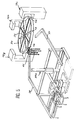
- the packaging robot represented in FIGS. 1 to 3 corresponds to one of the two constituent parts of the device according to the invention, the other part being constituted by a secondary robot 29 (FIG. 4) or 29a (FIG. 5) which is described. later.
- the main robot comprises a series of manipulation hands designated by the general reference 1. Each of these hands is carried by an individual support 2. In the example shown, this consists of a carriage mounted mobile on a guide rail formed by a metal profile 3 imparting a closed circuit trajectory to all of the corresponding carriages. Instead of a single rail, it would be possible to provide several guide rails.
- the profile 3 has a section in C and each carriage 2 has a vertical plate 4 disposed opposite the opening of this profile. This plate serves as a support for wheels 5 arranged inside the section 3 and placed in contact with the bottom of the latter.
- the movement of each carriage is ensured by an electric motor 6 driving a pinion 7 meshing with a rack 8 provided against the bottom of the profile 3.
- the supply of motor 6 with electric current is ensured from conductive tracks 9 carried by the bottom profile 3 and against which slide contacts 10 provided on each carriage.
- this consists of a clamp 12 fixed at the end of a horizontal arm 13 which is mounted both sliding in the axial direction and rotating on itself inside a support 14.
- the latter is itself capable of sliding vertically along a vertical rod 15 carried by the housing 11.
- This latter movement is controlled by an electric motor 16, two other motors, respectively 17 and 18 controlling the sliding on the one hand of the arm 13 and on the other hand the rotation of the latter on itself.
- the gripper 12 forming a handling hand can be moved in any direction in space.
- the first of these stations 19a is arranged immediately after a station 21 for handling each of the bottles to be packaged.
- the last station 19f it is located immediately before a station 22 for returning the bottles after completion of the packaging operations.
- the device according to the invention can be designed and adapted to all other kinds of packaging operations in packaging or containers of various kinds, for example cans or other containers, cardboard or plastic boxes, etc.
- the products to be packaged they can themselves be of very different natures. Indeed it can be liquid, powdery, granular, solid, etc. products.
- the various work stations are devoid of means for handling the packages to be treated, in this case the bottles 20.
- the handling of each bottle is ensured by the same hand 1 which holds it.
- This is therefore a completely different solution from that provided in conventional packaging chains made up of a plurality of different devices, each of which is sufficient by itself to fulfill a single function and includes means for handling capable of taking over a packaging at the entrance of this device to deposit it at the exit after completion of the corresponding operation.
- the solution is quite different since each packaging is supported by a handling hand at the place of the departure station 20 to be released only at the return station 22.
- the corresponding handling hand ensures on the one hand the transfer of the corresponding packaging from one work station to the next and on the other hand, at the location of each station, the various manipulations necessary to place the corresponding packaging in the desired position or positions in space so that the working members of this station can perform the desired operations on this packaging.
- each handling hand 1 has a bottle 20 in an inverted position to engage its neck on a nozzle 23 for injecting water.
- each hand 1 presents the corresponding bottle in an opposite position to engage its neck on a filling nozzle 24.
- each hand allocates other movements to each bottle in the different other workstations, and this depending on the nature of the operation provided in each of them.
- the control of the particular manipulations provided for at the place of each work station is ensured from a control device fitted to each of them and which is provided with a particular program.
- the electrical circuit of this control device is connected to conductive tracks 25 provided on the base 26 of each work station.
- the trolleys 2 carry each a series of contacts 27 provided on a vertical plate 28 and which are capable of coming into contact with the different tracks 25 of a work station, when the corresponding carriage has reached the location thereof. These contacts are connected to the supply circuits of the various motors 16, 17 and 18.
- the actuating members of each manipulation hand receive the pulses necessary to impart to them the desired movements, and this as a function of the the very nature of the operations planned in each work station.
- the conductive tracks 9 provided in the guide rail 3 are interrupted at the location of each work station to ensure the stopping of each carriage 2 at the location thereof, a braking and stopping device being able to besides being expected. As for the restart, it can be ensured from an impulse provided by some of the tracks 25 of each work station.
- the planned arrangement ensures the programmed advance of the various carriages 2.
- this packaging device allows great flexibility of adaptation to different work and this, depending on the nature of the products to be packaged as well as the type of packaging provided.
- the program for controlling the carriages 2 and the handling hands can be modified or replaced by a different program so that one or more stations are "skipped" and taken out of service.
- the work stations 19a, 19b, ... are mounted movable so that they can be removed to be replaced by stations suitable for performing different operations.
- these stations can be mounted on casters while being equipped with a locking device in their position of use. We can therefore quickly modify a packaging robot according to the invention to adapt it to different packaging jobs.
- this secondary robot 29 can also be used to supply the station 21 with bottles 20 at the place where these are taken care of by the main robot.
- this secondary robot 29 is constituted by the conditioning device which is the subject of patent FR 2,591,927.
- This device includes one or more working tools 32 arranged at the end of a shaft 33 mounted movably on a vertical column 34.
- the operation of this robot is ensured by a control system, which gives it the various displacements necessary to perform the operations provided, in particular, in the example shown: opening of cardboard boxes 35 initially folded flat, filling of the boxes 30 thus obtained, then closing of these and evacuation.
- the device according to the invention can be the subject of various variants and other embodiments, and in particular depending on the nature of the products to be packaged and the type of packaging provided.
- the handling hands 1 instead of grabbing a single bottle 20 at a time, the handling hands 1 provided in the case illustrated in FIGS. 1 to 4 can be arranged to grab two bottles at a time or more, or any other type of packaging.
- the handling hands can be arranged to include an additional degree of freedom (double rotation). Instead of being formed by pliers, these hands may include any other gripping members, for example vacuum suction cups, etc.
- each handling hand 1 abandons, along the way, the packaging 20 seized by it, to go and resume, in front, a similar packaging abandoned before by a previous handling hand, And so on.
- This operation can take place at the location of one or more specific work stations, each package 20 being left there after handling and placed in the desired position for the execution of the operations provided for in this station.
- handling hands are used to transport one or more several specific tools to be adapted on certain workstations.
- the movements of the handling hands can be done by a central device, the desired electrical connections being ensured by additional conductive tracks provided on the rail. guide 3.
- the different handling hands of such a device can be carried, not by individual supports as is the case in FIGS. 1 to 4, but by a single mobile support ensuring the movement of all of these hands.
- Such an embodiment is moreover shown in FIG. 5.
- a series of manipulation hands 1a are provided, disposed at the periphery of a common support 2a in the form of a wheel, which is rotatably mounted around a vertical shaft 36.
- This support therefore gives a circular trajectory to the set of handling hands 1a.
- the work stations 19g, 19h and 19i of the corresponding device are arranged around the rotary support 2a, so that each handling hand 1a can successively bring one or more packages to the place of each of these stations.
- the handling hands 1a are able to impart to the packaging seized by each of them, the different movements and manipulations which are necessary in each work station depending on the nature of the operations provided for therein. .
- the handling hands 1a can be designed to grip intermediate supports 41 each carrying one or more packages, as shown in FIG. 5.
- Such a solution may indeed be more advantageous in the case of certain types of packaging.
- Such a solution could also be adopted in the case of the embodiments according to FIGS. 1 and 4.
- each manipulation hand 1a can be ensured by mechanical drive means, for example by separate motors receiving operating instructions from a central control system, suitable synchronization being provided for that at the location of each station the handling hand there receives the desired operating instructions.
- the packaging device thus formed does not have the same flexibility or the same advantages as the devices according to FIGS. 1 to 3. However, it may be suitable in the case of relatively simple and few packaging operations.
- this device can be associated with a secondary robot 29a of the same type as the robot 29 provided in the case of Figure 4.
- This secondary robot is then connected to the main robot by two conveyors, namely a conveyor upstream 37 for feeding the main robot and a conveyor 38 for evacuating the packages treated in this robot.
- the secondary robot 29a it is then arranged to carry out the same operations as the robot 29 in FIG. 4.
- these units each designated by the general reference 39, can then be mounted in parallel following a single supply station 40.
Landscapes
- Engineering & Computer Science (AREA)
- Mechanical Engineering (AREA)
- Robotics (AREA)
- Container Filling Or Packaging Operations (AREA)
- Specific Conveyance Elements (AREA)
Claims (12)
- Vorrichtung zum Verpacken von verschiedenen Produkten in einzelnen Packungen geeigneter Art, mit- wenigstens einem Halter (2, 2a),- wenigstens einem Steuerschuh (1, 1a), der vom Halter (2, 2a) getragen ist, und Wenigstens eine einzelne Packung halten kann, sowie Einrichtungen (6, 7, 8) zum Betätigen des Steuerschuhs (1, 1a), die vom Halter (2, 2a) getragen sind und dem Steuerschuh (1, 1a) Bewegungen zum Steuern der Pakkung im Raum bezüglich des Halters (2, 2a) geben können,- Einrichtungen (3, 6, 36) zum Versetzen des Halters (2, 2a) längs einer bestimmten Bahn,- mehreren Arbeitsstationen (19a-19i), die der Bahn gegenüberstehend angeordnet sind und von denen jede mit dem Steuerschuh (1, 1a) zusammenarbeiten kann, wenn dieser auf dessen Stelle trifft, um einen bestimmten Arbeitsvorgang jeweils der Verpackung auszuführen,- Einrichtungen (9, 10, 25, 27) zum Steuern einerseits der Einrichtungen (3, 6, 36) zum Versetzen, um den Steuerschuh (1, 1a) nacheinander an der Stelle der verschiedenen Arbeitsstationen anzuordnen, und andererseits zum Steuern jeder Arbeitsstation (19a-19i) und der Einrichtungen (16, 17, 18) zum Betätigen des Steuerschuhs (1, 1a), wenn diese zusammentreffen, um den bestimmten Arbeitsvorgang jeweils der Verpackung auszuführen, wobei die Steuereinrichtungen (19, 25, 27) insbesondere an jeder Arbeitsstation (19a-19i) Leitungseinrichtungen (35) zwischen der Arbeitsstation (19a-19i) und dem Steuerschuh (1, 1a), der auf dessen Stelle trifft, aufweist, um relative Anweisungen bezüglich des bestimmten Arbeitsvorganges hinsichtlich der Verpackung zu geben, dadurch gekennzeichnet, daß die Steuereinrichtungen (19, 25, 27) an jeder Arbeitsstation (19a-19i) eine jeweilige Befehlseinrichtung aufweisen, die mit einem bestimmten Programm versehen ist, um auf die Einrichtungen (16, 17, 18) zum Betätigen des Steuerschuhs (1, 1a), der sich an der Stelle der Arbeitsstation (19a-19i) befindet, über die jeweiligen Leitungseinrichtungen (25) für die Befehlsanweisungen Anweisungen für die Bewegungen dieses Steuerschuhs (1, 1a) in Abhängigkeit von dem jeweiligen bestimmten Arbeitsvorgang zu geben.
- Vorrichtung nach Anspruch 1, dadurch gekennzeichnet, daß, der Kalter (2a) mehreren Steuerschuhen (1a) gemeinsam ist und die Form eines Rades hat, das um eine Achse (36) drehbar angebracht ist und an dessen Außenumfang die Steuerschuhe (1a) angebracht sind, die eine kreisförmige Bahn beschreiben.
- Vorrichtung nach Anspruch 1, dadurch gekennzeichnet, daß mehrere Halter in Form einer Anordnung von Schlitten (2) vorgesehen sind, von denen jeder einen Steuerschuh (1) jeweils trägt und die auf wenigstens einer Führungsschiene (3) gehalten sind, die ihnen eine Bahn in Form eines geschlossenen Kreises gibt.
- Vorrichtung nach Anspruch 3, dadurch gekennzeichnet, daß die Führungsschiene (3) eine Zahnstange (8) ist und daß jeder Antriebsmotor (6) ein Ritzel (7) trägt, das mit der Zahnstange (8) in Eingriff steht.
- Vorrichtung nach einem der Ansprüche 3 und 4, dadurch gekennzeichnet, daß jeder Schlitten (2) einen Antriebselektromotor (6) aufweist, daß die Führungsschiene (3) Leiterbahnen (9) zur elektrischen Versorgung des Antriebsmotors (6) der Schlitten (2) aufweist und daß jeder Schlitten (2) elektrische Versorgungskontakte (10) des Motors (6) aufweist, die an den versorgungsleiterbahnen (9) entlanggleiten.
- Vorrichtung nach Anspruch 5, dadurch gekennzeichnet, daß die Versorgungsleiterbahnen (9) an der Stelle einer Arbeitsstation (19a-19f) unterbrochen sind, um das Anhalten jedes Schlittens (2) an dieser Stelle sicherzustellen.
- Vorrichtung nach einem der Ansprüche 1 bis 6, dadurch gekennzeichnet, daß die Leitungseinrichtungen (25) für die Anweisungen an jeder Arbeitsstation (19a-19i) Leiterbahnen (25) jeweils umfassen und daß der oder jeder Steuerschuh (1, 1a) jeweils mit Kontakten (27) versehen ist, die mit den Einrichtungen (16, 17, 18) zum Betätigen verbunden sind und in Kontakt mit den Leiterbahnen (25) einer Arbeitsstation (19a-19i) kommen, wenn der Steuerschuh (1, 1a) sich an dessen Stelle einfindet.
- Vorrichtung nach Anspruch 6 und 7, dadurch gekennzeichnet, daß das Wiederanfahren eines Schlittens (2), der an der Stelle einer Arbeitsstation (19a-19f) angehalten ist, über einen Impuls bewirkt wird, der über die Leiterbahnen (25) der Arbeitsstation (19a-19f) kommt.
- Vorrichtung nach einem der Ansprüche 1 bis 8, dadurch gekennzeichnet, daß der Steuerschuh (1) eine Klammer (12) aufweist, die am Ende eines horizontalen Armes (13) befestigt ist, der seinerseits verschiebbar in axialer Richtung und um sich selbst im Inneren eines Halters (14) drehbar ist, der vertikal bezüglich des Halters (2, 2a) verschiebbar ist, und daß die Einrichtungen (16, 17, 18) zum Betätigen des Steuerschuhs elektrische Motoren (16, 17, 18) umfassen, die jeweils die Verschiebung des Armes (13), die Drehung und Verschiebung des Halters (14) so steuern, daß die Klammer (12) in jeder Richtung im Raum unter der Steuerung einer Steuereinrichtung versetzt wird, die an der Arbeitsstation (19a-19i) vorgesehen ist.
- Vorrichtung nach einem der Ansprüche 1 bis 9, dadurch gekennzeichnet, daß die Arbeitsstationen (19a-19i) austauschbar sind, wobei die Stationen verschiedene Arbeitsvorgänge bewirken können.
- Anlage mit einer Vorrichtung nach einem der Ansprüche 1 bis 10, dadurch gekennzeichnet, daß ein sekundärer Roboter (29, 29a), der eines oder mehrere Arbeitswerkzeuge (32) aufweist, die am Ende einer Achse (33) angebracht sind, die beweglich an einer vertikalen Säule (34) angebracht ist, dazu vorgesehen ist, eine Station (21) mit Produkten (20) zu versorgen, um die Produkte (20) vom Steuerschuh (1) zu übernehmen.
- Anlage mit einer Vorrichtung nach einem der Ansprüche 1 bis 10, dadurch gekennzeichnet, daß nach den durch die Vorrichtung ausgeführten Arbeitsvorgängen ein Sekundärroboter (29, 29a) einen oder mehrere der folgenden komplementären Arbeitsvorgänge ausführt: Umgruppierung der Produkte (20) in Schachteln, Füllen und Schließen der Umgruppierungsschachteln, Anordnen der Schachteln an einer Evakuuierungs- und Transporteinrichtung.
Applications Claiming Priority (2)
| Application Number | Priority Date | Filing Date | Title |
|---|---|---|---|
| FR8916779A FR2655945B1 (fr) | 1989-12-19 | 1989-12-19 | Procede et dispositif pour le conditionnement de produits divers. |
| FR8916779 | 1989-12-19 |
Publications (2)
| Publication Number | Publication Date |
|---|---|
| EP0434542A1 EP0434542A1 (de) | 1991-06-26 |
| EP0434542B1 true EP0434542B1 (de) | 1994-09-14 |
Family
ID=9388670
Family Applications (1)
| Application Number | Title | Priority Date | Filing Date |
|---|---|---|---|
| EP90403637A Expired - Lifetime EP0434542B1 (de) | 1989-12-19 | 1990-12-18 | Vorrichtung zum Verpacken von verschiedenen Produkten |
Country Status (3)
| Country | Link |
|---|---|
| EP (1) | EP0434542B1 (de) |
| DE (1) | DE69012532T2 (de) |
| FR (1) | FR2655945B1 (de) |
Families Citing this family (9)
| Publication number | Priority date | Publication date | Assignee | Title |
|---|---|---|---|---|
| FR2714042B1 (fr) * | 1993-12-20 | 1996-03-08 | Girardin Packaging | Machine pour le conditionnement de produits de parfumerie, de cosmétologie et de pharmacie. |
| EP1201599A1 (de) * | 2000-10-27 | 2002-05-02 | SIG Simonazzi S.p.A. | System zur Förderung von zu verarbeitenden Gegenständen |
| DE10102758A1 (de) * | 2001-01-23 | 2002-07-25 | Volkswagen Ag | Vorrichtung zur Bearbeitung von Bauteilen |
| DE102008006170B4 (de) * | 2008-01-26 | 2018-01-04 | Eisenmann Se | Vorrichtung zur Handhabung von Gegenständen |
| DE102009009244A1 (de) * | 2009-02-17 | 2010-08-26 | Jürgen Löhrke GmbH | Reinigungssystem und Reinigungsverfahren |
| CN104117869B (zh) * | 2014-06-04 | 2016-08-24 | 伟本机电(上海)有限公司 | 工件机床加工自动上下料线 |
| DE102019121393A1 (de) * | 2019-08-08 | 2021-02-11 | Krones Ag | Behandlungsvorrichtung und Verfahren zur Herstellung einer Behandlungsvorrichtung |
| DE102020114084A1 (de) | 2020-05-26 | 2021-12-02 | Syntegon Packaging Systems Ag | Handhabungsvorrichtung sowie Verfahren zu einem Handhaben von mittels einer Transportvorrichtung geförderten Produkten, insbesondere Lebensmitteln |
| BE1028746B1 (nl) * | 2020-10-27 | 2022-05-24 | Anheuser Busch Inbev | Een systeem voor het hanteren van afzonderlijke primaire verpakkingshouders |
Family Cites Families (4)
| Publication number | Priority date | Publication date | Assignee | Title |
|---|---|---|---|---|
| FR2465477B1 (fr) * | 1979-09-21 | 1985-09-06 | Publimepharm | Procede et dispositif a transfert circulaire pour le conditionnement automatise d'ampoules pharmaceutiques |
| FR2591927B1 (fr) * | 1985-12-24 | 1991-01-11 | Thibault Jacques | Tete de prehension et son application a un robot et a une installation de conditionnement |
| DE3614165A1 (de) * | 1986-04-26 | 1987-10-29 | Kloeckner Humboldt Deutz Ag | Transportsystem fuer serienfertigungen |
| DE3623350A1 (de) * | 1986-07-11 | 1988-04-07 | Fraunhofer Ges Forschung | Verfahren und vorrichtung zum automatischen handhaben von gegenstaenden im dreidimensionalen raum |
-
1989
- 1989-12-19 FR FR8916779A patent/FR2655945B1/fr not_active Expired - Lifetime
-
1990
- 1990-12-18 DE DE69012532T patent/DE69012532T2/de not_active Expired - Fee Related
- 1990-12-18 EP EP90403637A patent/EP0434542B1/de not_active Expired - Lifetime
Also Published As
| Publication number | Publication date |
|---|---|
| DE69012532T2 (de) | 1995-05-11 |
| FR2655945A1 (fr) | 1991-06-21 |
| EP0434542A1 (de) | 1991-06-26 |
| DE69012532D1 (de) | 1994-10-20 |
| FR2655945B1 (fr) | 1992-04-03 |
Similar Documents
| Publication | Publication Date | Title |
|---|---|---|
| FR2652529A1 (fr) | Robot. | |
| FR2623481A1 (fr) | Appareil automatique de montage | |
| EP0169156A1 (de) | Selbstangetriebener Wagen mit Fördereinrichtung durch Roboter | |
| EP0434542B1 (de) | Vorrichtung zum Verpacken von verschiedenen Produkten | |
| EP2196395A1 (de) | Vorrichtung und Verfahren zur Verpackung von Spritzen in Nestern | |
| EP0123655A2 (de) | Automatischer Apparat zum Verpacken von Obst- und Gemüsebehältern mittels einer Netzumwicklung versehen mit Stützbändern und Etiketten | |
| EP2341001A1 (de) | Verfahren und Maschine zur Umverpackung von Artikeln zur Bildung von Artikellosen, bestehend aus einer Vielzahl von Artikeln und einer Umverpackung aus Karton | |
| EP2099681A1 (de) | Vorrichtung zur verpackung mindestens eines objekts in einem bündel | |
| EP3902662B1 (de) | Vorrichtung zum zubereiten und abfüllen von flaschen | |
| EP3630615B1 (de) | Anlage zur herstellung von behältern mittels thermoformen | |
| EP0424226A1 (de) | Verpackungsmaschine zum Verschliessen von Verpackungsschalen oder dergleichen nach ihrer Befüllung, mittels einer heisssiegelbaren Folie | |
| EP0115989A1 (de) | Verfahren zum automatischen Füllen und Verschliessen von Behältern und Vorrichtung zur Durchführung des Verfahrens | |
| EP0402225B1 (de) | Fördereinrichtung für Behälter, wie Flaschen | |
| FR2531926A1 (fr) | Appareil pour envelopper, suivant un mouvement continu, des bonbons ou articles similaires dans une enveloppe ou " papillote " a double tortillon | |
| JPH0466414A (ja) | 容器処理装置 | |
| FR2589139A1 (fr) | Conditionnement automatique dans des recipients | |
| EP0429318B1 (de) | Verfahren und Vorrichtung zum Überführen von Deckeln oder dgl. in eine Maschine zum sterilen Konditionieren von Behältern | |
| WO2012056185A2 (fr) | Dispositif et procédé pour le suremballage de produits identiques ou similaires et l'encaissage des produits suremballes. | |
| FR2493805A1 (fr) | Procede et machine pour constituer, remplir, fermer un contenant de forme generale parallelepipedique a partir d'une forme aplatie | |
| FR2707597A1 (fr) | Procédé pour alimenter en pièces de tabac, en particulier des cigarettes, une machine d'empaquetage en continu. | |
| EP0050083B1 (de) | Gerät zur Gruppierung von Einheitsbehältern | |
| FR2810297A1 (fr) | Distributeur automatique de couvercles sur des boites | |
| FR2971496A1 (fr) | Outil de manipulation de produits | |
| EP4031454A1 (de) | Vorrichtung und verfahren zur herstellung eines behälters durch falten | |
| EP0083385B1 (de) | Verfahren zur Behandlung von Lebensmitteln in plastischen Behältern und Einrichtung hierfür, sowie zur Sterilisierung dieser Waren |
Legal Events
| Date | Code | Title | Description |
|---|---|---|---|
| PUAI | Public reference made under article 153(3) epc to a published international application that has entered the european phase |
Free format text: ORIGINAL CODE: 0009012 |
|
| AK | Designated contracting states |
Kind code of ref document: A1 Designated state(s): BE CH DE ES GB IT LI |
|
| 17P | Request for examination filed |
Effective date: 19911205 |
|
| 17Q | First examination report despatched |
Effective date: 19921221 |
|
| GRAA | (expected) grant |
Free format text: ORIGINAL CODE: 0009210 |
|
| AK | Designated contracting states |
Kind code of ref document: B1 Designated state(s): BE CH DE ES GB IT LI |
|
| PG25 | Lapsed in a contracting state [announced via postgrant information from national office to epo] |
Ref country code: IT Free format text: LAPSE BECAUSE OF FAILURE TO SUBMIT A TRANSLATION OF THE DESCRIPTION OR TO PAY THE FEE WITHIN THE PRESCRIBED TIME-LIMIT;WARNING: LAPSES OF ITALIAN PATENTS WITH EFFECTIVE DATE BEFORE 2007 MAY HAVE OCCURRED AT ANY TIME BEFORE 2007. THE CORRECT EFFECTIVE DATE MAY BE DIFFERENT FROM THE ONE RECORDED. Effective date: 19940914 Ref country code: ES Free format text: THE PATENT HAS BEEN ANNULLED BY A DECISION OF A NATIONAL AUTHORITY Effective date: 19940914 |
|
| REF | Corresponds to: |
Ref document number: 69012532 Country of ref document: DE Date of ref document: 19941020 |
|
| GBT | Gb: translation of ep patent filed (gb section 77(6)(a)/1977) |
Effective date: 19941213 |
|
| PLBE | No opposition filed within time limit |
Free format text: ORIGINAL CODE: 0009261 |
|
| STAA | Information on the status of an ep patent application or granted ep patent |
Free format text: STATUS: NO OPPOSITION FILED WITHIN TIME LIMIT |
|
| 26N | No opposition filed | ||
| PGFP | Annual fee paid to national office [announced via postgrant information from national office to epo] |
Ref country code: CH Payment date: 19951227 Year of fee payment: 6 |
|
| PGFP | Annual fee paid to national office [announced via postgrant information from national office to epo] |
Ref country code: BE Payment date: 19960117 Year of fee payment: 6 |
|
| PG25 | Lapsed in a contracting state [announced via postgrant information from national office to epo] |
Ref country code: CH Effective date: 19961231 Ref country code: LI Effective date: 19961231 Ref country code: BE Effective date: 19961231 |
|
| BERE | Be: lapsed |
Owner name: THIBAULT JACQUES GABRIEL AUGUSTE Effective date: 19961231 |
|
| REG | Reference to a national code |
Ref country code: CH Ref legal event code: PL |
|
| PGFP | Annual fee paid to national office [announced via postgrant information from national office to epo] |
Ref country code: GB Payment date: 20001222 Year of fee payment: 11 |
|
| PGFP | Annual fee paid to national office [announced via postgrant information from national office to epo] |
Ref country code: DE Payment date: 20010116 Year of fee payment: 11 |
|
| PG25 | Lapsed in a contracting state [announced via postgrant information from national office to epo] |
Ref country code: GB Free format text: LAPSE BECAUSE OF NON-PAYMENT OF DUE FEES Effective date: 20011218 |
|
| REG | Reference to a national code |
Ref country code: GB Ref legal event code: IF02 |
|
| PG25 | Lapsed in a contracting state [announced via postgrant information from national office to epo] |
Ref country code: DE Free format text: LAPSE BECAUSE OF NON-PAYMENT OF DUE FEES Effective date: 20020702 |
|
| GBPC | Gb: european patent ceased through non-payment of renewal fee |
Effective date: 20011218 |