EP0434501B1 - Verfahren zur Herstellung eines fasermatrix-keramischen Verbundwerkstoffs - Google Patents
Verfahren zur Herstellung eines fasermatrix-keramischen Verbundwerkstoffs Download PDFInfo
- Publication number
- EP0434501B1 EP0434501B1 EP90403533A EP90403533A EP0434501B1 EP 0434501 B1 EP0434501 B1 EP 0434501B1 EP 90403533 A EP90403533 A EP 90403533A EP 90403533 A EP90403533 A EP 90403533A EP 0434501 B1 EP0434501 B1 EP 0434501B1
- Authority
- EP
- European Patent Office
- Prior art keywords
- polysilane
- process according
- liquid
- particles
- silicon carbide
- Prior art date
- Legal status (The legal status is an assumption and is not a legal conclusion. Google has not performed a legal analysis and makes no representation as to the accuracy of the status listed.)
- Expired - Lifetime
Links
- 238000000034 method Methods 0.000 title claims description 30
- 230000008569 process Effects 0.000 title claims description 25
- 239000011159 matrix material Substances 0.000 title claims description 22
- 239000002131 composite material Substances 0.000 title claims description 12
- 239000000919 ceramic Substances 0.000 title claims description 10
- 238000002360 preparation method Methods 0.000 title description 3
- 229920000548 poly(silane) polymer Polymers 0.000 claims description 35
- HBMJWWWQQXIZIP-UHFFFAOYSA-N silicon carbide Chemical compound [Si+]#[C-] HBMJWWWQQXIZIP-UHFFFAOYSA-N 0.000 claims description 31
- 239000007788 liquid Substances 0.000 claims description 28
- 239000002245 particle Substances 0.000 claims description 27
- 229910010271 silicon carbide Inorganic materials 0.000 claims description 27
- 239000000126 substance Substances 0.000 claims description 18
- 238000011282 treatment Methods 0.000 claims description 16
- OKTJSMMVPCPJKN-UHFFFAOYSA-N Carbon Chemical compound [C] OKTJSMMVPCPJKN-UHFFFAOYSA-N 0.000 claims description 15
- 229910052799 carbon Inorganic materials 0.000 claims description 14
- IJOOHPMOJXWVHK-UHFFFAOYSA-N chlorotrimethylsilane Chemical compound C[Si](C)(C)Cl IJOOHPMOJXWVHK-UHFFFAOYSA-N 0.000 claims description 9
- 238000001914 filtration Methods 0.000 claims description 9
- 239000000463 material Substances 0.000 claims description 9
- 238000004132 cross linking Methods 0.000 claims description 8
- 239000000178 monomer Substances 0.000 claims description 8
- 229910010293 ceramic material Inorganic materials 0.000 claims description 7
- 239000000203 mixture Substances 0.000 claims description 7
- 239000000725 suspension Substances 0.000 claims description 7
- 230000008021 deposition Effects 0.000 claims description 6
- 229930195733 hydrocarbon Natural products 0.000 claims description 4
- 230000003993 interaction Effects 0.000 claims description 4
- 238000010438 heat treatment Methods 0.000 claims description 3
- 125000002887 hydroxy group Chemical group [H]O* 0.000 claims description 3
- 239000007791 liquid phase Substances 0.000 claims description 3
- 238000004519 manufacturing process Methods 0.000 claims description 3
- -1 sodium halide Chemical class 0.000 claims description 3
- BLRPTPMANUNPDV-UHFFFAOYSA-N Silane Chemical class [SiH4] BLRPTPMANUNPDV-UHFFFAOYSA-N 0.000 claims description 2
- 230000009471 action Effects 0.000 claims description 2
- 229910052708 sodium Inorganic materials 0.000 claims 6
- 239000011734 sodium Substances 0.000 claims 6
- DGAQECJNVWCQMB-PUAWFVPOSA-M Ilexoside XXIX Chemical compound C[C@@H]1CC[C@@]2(CC[C@@]3(C(=CC[C@H]4[C@]3(CC[C@@H]5[C@@]4(CC[C@@H](C5(C)C)OS(=O)(=O)[O-])C)C)[C@@H]2[C@]1(C)O)C)C(=O)O[C@H]6[C@@H]([C@H]([C@@H]([C@H](O6)CO)O)O)O.[Na+] DGAQECJNVWCQMB-PUAWFVPOSA-M 0.000 claims 4
- YXFVVABEGXRONW-UHFFFAOYSA-N Toluene Chemical compound CC1=CC=CC=C1 YXFVVABEGXRONW-UHFFFAOYSA-N 0.000 claims 3
- 239000004215 Carbon black (E152) Substances 0.000 claims 2
- 125000004435 hydrogen atom Chemical group [H]* 0.000 claims 2
- 239000007790 solid phase Substances 0.000 claims 2
- 239000002904 solvent Substances 0.000 claims 2
- RYHBNJHYFVUHQT-UHFFFAOYSA-N 1,4-Dioxane Chemical compound C1COCCO1 RYHBNJHYFVUHQT-UHFFFAOYSA-N 0.000 claims 1
- XUIMIQQOPSSXEZ-UHFFFAOYSA-N Silicon Chemical group [Si] XUIMIQQOPSSXEZ-UHFFFAOYSA-N 0.000 claims 1
- BUMGIEFFCMBQDG-UHFFFAOYSA-N dichlorosilicon Chemical compound Cl[Si]Cl BUMGIEFFCMBQDG-UHFFFAOYSA-N 0.000 claims 1
- 125000005843 halogen group Chemical group 0.000 claims 1
- 239000003960 organic solvent Substances 0.000 claims 1
- 238000006116 polymerization reaction Methods 0.000 claims 1
- 229920001187 thermosetting polymer Polymers 0.000 claims 1
- 239000000835 fiber Substances 0.000 description 47
- 239000012071 phase Substances 0.000 description 23
- 239000000843 powder Substances 0.000 description 16
- 239000004744 fabric Substances 0.000 description 12
- 238000000197 pyrolysis Methods 0.000 description 10
- CSCPPACGZOOCGX-UHFFFAOYSA-N Acetone Chemical compound CC(C)=O CSCPPACGZOOCGX-UHFFFAOYSA-N 0.000 description 8
- VYPSYNLAJGMNEJ-UHFFFAOYSA-N Silicium dioxide Chemical compound O=[Si]=O VYPSYNLAJGMNEJ-UHFFFAOYSA-N 0.000 description 8
- 238000005470 impregnation Methods 0.000 description 7
- 229920000642 polymer Polymers 0.000 description 7
- 230000008595 infiltration Effects 0.000 description 6
- 238000001764 infiltration Methods 0.000 description 6
- IJGRMHOSHXDMSA-UHFFFAOYSA-N Atomic nitrogen Chemical compound N#N IJGRMHOSHXDMSA-UHFFFAOYSA-N 0.000 description 5
- 230000002457 bidirectional effect Effects 0.000 description 5
- 239000002243 precursor Substances 0.000 description 5
- 239000011184 SiC–SiC matrix composite Substances 0.000 description 4
- 238000006243 chemical reaction Methods 0.000 description 4
- 239000007789 gas Substances 0.000 description 4
- 239000002609 medium Substances 0.000 description 4
- 239000011148 porous material Substances 0.000 description 4
- 239000000377 silicon dioxide Substances 0.000 description 4
- 238000001757 thermogravimetry curve Methods 0.000 description 4
- 239000005051 trimethylchlorosilane Substances 0.000 description 4
- KFZMGEQAYNKOFK-UHFFFAOYSA-N Isopropanol Chemical compound CC(C)O KFZMGEQAYNKOFK-UHFFFAOYSA-N 0.000 description 3
- 238000010586 diagram Methods 0.000 description 3
- 239000012467 final product Substances 0.000 description 3
- 238000007654 immersion Methods 0.000 description 3
- 239000010410 layer Substances 0.000 description 3
- 230000003014 reinforcing effect Effects 0.000 description 3
- 238000005245 sintering Methods 0.000 description 3
- QGZKDVFQNNGYKY-UHFFFAOYSA-N Ammonia Chemical compound N QGZKDVFQNNGYKY-UHFFFAOYSA-N 0.000 description 2
- VGGSQFUCUMXWEO-UHFFFAOYSA-N Ethene Chemical compound C=C VGGSQFUCUMXWEO-UHFFFAOYSA-N 0.000 description 2
- 239000005977 Ethylene Substances 0.000 description 2
- 229910008051 Si-OH Inorganic materials 0.000 description 2
- 229910052581 Si3N4 Inorganic materials 0.000 description 2
- 229910006358 Si—OH Inorganic materials 0.000 description 2
- QVGXLLKOCUKJST-UHFFFAOYSA-N atomic oxygen Chemical compound [O] QVGXLLKOCUKJST-UHFFFAOYSA-N 0.000 description 2
- 238000000576 coating method Methods 0.000 description 2
- 238000000354 decomposition reaction Methods 0.000 description 2
- 238000004455 differential thermal analysis Methods 0.000 description 2
- 229910002804 graphite Inorganic materials 0.000 description 2
- 239000010439 graphite Substances 0.000 description 2
- 150000002430 hydrocarbons Chemical class 0.000 description 2
- 150000002500 ions Chemical class 0.000 description 2
- 239000012705 liquid precursor Substances 0.000 description 2
- 229910003465 moissanite Inorganic materials 0.000 description 2
- 229910052757 nitrogen Inorganic materials 0.000 description 2
- 239000001301 oxygen Substances 0.000 description 2
- 229910052760 oxygen Inorganic materials 0.000 description 2
- 229920006395 saturated elastomer Polymers 0.000 description 2
- 229910052710 silicon Inorganic materials 0.000 description 2
- 239000010703 silicon Substances 0.000 description 2
- 238000002076 thermal analysis method Methods 0.000 description 2
- XLYOFNOQVPJJNP-UHFFFAOYSA-N water Substances O XLYOFNOQVPJJNP-UHFFFAOYSA-N 0.000 description 2
- 239000004925 Acrylic resin Substances 0.000 description 1
- 229920000178 Acrylic resin Polymers 0.000 description 1
- 229910052582 BN Inorganic materials 0.000 description 1
- PZNSFCLAULLKQX-UHFFFAOYSA-N Boron nitride Chemical compound N#B PZNSFCLAULLKQX-UHFFFAOYSA-N 0.000 description 1
- GUBGYTABKSRVRQ-QKKXKWKRSA-N Lactose Natural products OC[C@H]1O[C@@H](O[C@H]2[C@H](O)[C@@H](O)C(O)O[C@@H]2CO)[C@H](O)[C@@H](O)[C@H]1O GUBGYTABKSRVRQ-QKKXKWKRSA-N 0.000 description 1
- 150000001338 aliphatic hydrocarbons Chemical class 0.000 description 1
- 229910021529 ammonia Inorganic materials 0.000 description 1
- 238000004458 analytical method Methods 0.000 description 1
- 239000012736 aqueous medium Substances 0.000 description 1
- 239000007900 aqueous suspension Substances 0.000 description 1
- 238000009835 boiling Methods 0.000 description 1
- 150000001721 carbon Chemical class 0.000 description 1
- 239000007795 chemical reaction product Substances 0.000 description 1
- 238000004140 cleaning Methods 0.000 description 1
- 239000011248 coating agent Substances 0.000 description 1
- 230000000052 comparative effect Effects 0.000 description 1
- 238000005336 cracking Methods 0.000 description 1
- 239000013078 crystal Substances 0.000 description 1
- 238000005520 cutting process Methods 0.000 description 1
- 230000007423 decrease Effects 0.000 description 1
- SWXVUIWOUIDPGS-UHFFFAOYSA-N diacetone alcohol Natural products CC(=O)CC(C)(C)O SWXVUIWOUIDPGS-UHFFFAOYSA-N 0.000 description 1
- KTQYJQFGNYHXMB-UHFFFAOYSA-N dichloro(methyl)silicon Chemical compound C[Si](Cl)Cl KTQYJQFGNYHXMB-UHFFFAOYSA-N 0.000 description 1
- YLJJAVFOBDSYAN-UHFFFAOYSA-N dichloro-ethenyl-methylsilane Chemical compound C[Si](Cl)(Cl)C=C YLJJAVFOBDSYAN-UHFFFAOYSA-N 0.000 description 1
- 238000006073 displacement reaction Methods 0.000 description 1
- 230000002349 favourable effect Effects 0.000 description 1
- 238000011049 filling Methods 0.000 description 1
- 238000007710 freezing Methods 0.000 description 1
- 230000008014 freezing Effects 0.000 description 1
- 239000003365 glass fiber Substances 0.000 description 1
- 238000001033 granulometry Methods 0.000 description 1
- 239000001257 hydrogen Substances 0.000 description 1
- 229910052739 hydrogen Inorganic materials 0.000 description 1
- 238000011065 in-situ storage Methods 0.000 description 1
- 239000011229 interlayer Substances 0.000 description 1
- 230000001788 irregular Effects 0.000 description 1
- 239000008101 lactose Substances 0.000 description 1
- 239000000314 lubricant Substances 0.000 description 1
- 239000005055 methyl trichlorosilane Substances 0.000 description 1
- 239000005048 methyldichlorosilane Substances 0.000 description 1
- JLUFWMXJHAVVNN-UHFFFAOYSA-N methyltrichlorosilane Chemical compound C[Si](Cl)(Cl)Cl JLUFWMXJHAVVNN-UHFFFAOYSA-N 0.000 description 1
- 239000003921 oil Substances 0.000 description 1
- 238000013001 point bending Methods 0.000 description 1
- 239000000047 product Substances 0.000 description 1
- 230000001105 regulatory effect Effects 0.000 description 1
- 230000002940 repellent Effects 0.000 description 1
- 239000005871 repellent Substances 0.000 description 1
- 150000003377 silicon compounds Chemical class 0.000 description 1
- HQVNEWCFYHHQES-UHFFFAOYSA-N silicon nitride Chemical compound N12[Si]34N5[Si]62N3[Si]51N64 HQVNEWCFYHHQES-UHFFFAOYSA-N 0.000 description 1
- 239000007858 starting material Substances 0.000 description 1
- 238000003756 stirring Methods 0.000 description 1
- 238000010408 sweeping Methods 0.000 description 1
- 238000005979 thermal decomposition reaction Methods 0.000 description 1
- UKRDPEFKFJNXQM-UHFFFAOYSA-N vinylsilane Chemical compound [SiH3]C=C UKRDPEFKFJNXQM-UHFFFAOYSA-N 0.000 description 1
- 230000003313 weakening effect Effects 0.000 description 1
- 238000009941 weaving Methods 0.000 description 1
Images




Classifications
-
- C—CHEMISTRY; METALLURGY
- C04—CEMENTS; CONCRETE; ARTIFICIAL STONE; CERAMICS; REFRACTORIES
- C04B—LIME, MAGNESIA; SLAG; CEMENTS; COMPOSITIONS THEREOF, e.g. MORTARS, CONCRETE OR LIKE BUILDING MATERIALS; ARTIFICIAL STONE; CERAMICS; REFRACTORIES; TREATMENT OF NATURAL STONE
- C04B41/00—After-treatment of mortars, concrete, artificial stone or ceramics; Treatment of natural stone
- C04B41/009—After-treatment of mortars, concrete, artificial stone or ceramics; Treatment of natural stone characterised by the material treated
-
- C—CHEMISTRY; METALLURGY
- C04—CEMENTS; CONCRETE; ARTIFICIAL STONE; CERAMICS; REFRACTORIES
- C04B—LIME, MAGNESIA; SLAG; CEMENTS; COMPOSITIONS THEREOF, e.g. MORTARS, CONCRETE OR LIKE BUILDING MATERIALS; ARTIFICIAL STONE; CERAMICS; REFRACTORIES; TREATMENT OF NATURAL STONE
- C04B35/00—Shaped ceramic products characterised by their composition; Ceramics compositions; Processing powders of inorganic compounds preparatory to the manufacturing of ceramic products
- C04B35/515—Shaped ceramic products characterised by their composition; Ceramics compositions; Processing powders of inorganic compounds preparatory to the manufacturing of ceramic products based on non-oxide ceramics
- C04B35/56—Shaped ceramic products characterised by their composition; Ceramics compositions; Processing powders of inorganic compounds preparatory to the manufacturing of ceramic products based on non-oxide ceramics based on carbides or oxycarbides
- C04B35/565—Shaped ceramic products characterised by their composition; Ceramics compositions; Processing powders of inorganic compounds preparatory to the manufacturing of ceramic products based on non-oxide ceramics based on carbides or oxycarbides based on silicon carbide
- C04B35/571—Shaped ceramic products characterised by their composition; Ceramics compositions; Processing powders of inorganic compounds preparatory to the manufacturing of ceramic products based on non-oxide ceramics based on carbides or oxycarbides based on silicon carbide obtained from Si-containing polymer precursors or organosilicon monomers
-
- C—CHEMISTRY; METALLURGY
- C04—CEMENTS; CONCRETE; ARTIFICIAL STONE; CERAMICS; REFRACTORIES
- C04B—LIME, MAGNESIA; SLAG; CEMENTS; COMPOSITIONS THEREOF, e.g. MORTARS, CONCRETE OR LIKE BUILDING MATERIALS; ARTIFICIAL STONE; CERAMICS; REFRACTORIES; TREATMENT OF NATURAL STONE
- C04B35/00—Shaped ceramic products characterised by their composition; Ceramics compositions; Processing powders of inorganic compounds preparatory to the manufacturing of ceramic products
- C04B35/71—Ceramic products containing macroscopic reinforcing agents
- C04B35/78—Ceramic products containing macroscopic reinforcing agents containing non-metallic materials
- C04B35/80—Fibres, filaments, whiskers, platelets, or the like
-
- C—CHEMISTRY; METALLURGY
- C04—CEMENTS; CONCRETE; ARTIFICIAL STONE; CERAMICS; REFRACTORIES
- C04B—LIME, MAGNESIA; SLAG; CEMENTS; COMPOSITIONS THEREOF, e.g. MORTARS, CONCRETE OR LIKE BUILDING MATERIALS; ARTIFICIAL STONE; CERAMICS; REFRACTORIES; TREATMENT OF NATURAL STONE
- C04B41/00—After-treatment of mortars, concrete, artificial stone or ceramics; Treatment of natural stone
- C04B41/45—Coating or impregnating, e.g. injection in masonry, partial coating of green or fired ceramics, organic coating compositions for adhering together two concrete elements
- C04B41/50—Coating or impregnating, e.g. injection in masonry, partial coating of green or fired ceramics, organic coating compositions for adhering together two concrete elements with inorganic materials
- C04B41/5053—Coating or impregnating, e.g. injection in masonry, partial coating of green or fired ceramics, organic coating compositions for adhering together two concrete elements with inorganic materials non-oxide ceramics
- C04B41/5057—Carbides
- C04B41/5059—Silicon carbide
Definitions
- the invention relates to the preparation of ceramic composite materials comprising a fibrous structure embedded in a matrix, and more particularly a structure of silicon carbide fibers embedded in a silicon carbide matrix.
- Composites of the latter type can be used at high temperature, for example as structural elements of heat engines.
- a conventional process for producing a composite fiber-ceramic matrix material consists in sintering ceramic particles together in the presence of the fibers. This process is not currently applicable to composite materials in which the fibers and the matrix are made of silicon carbide, hereinafter called SiC-SiC composites. Indeed, the sintering of a silicon carbide powder requires a temperature of the order of 2000 ° C., which alters the mechanical properties of known silicon carbide fibers.
- the process consisting in pyrolyzing a precursor previously introduced into the voids of the fibrous structure to form in situ the material of the matrix, used in particular for carbon matrices does not give good results in the case of matrices.
- silicon carbide due to the high theoretical density of this substance (3.2 against 2.26 for graphite), which results in a high volume shrinkage during the pyrolysis of a precursor of the polysilane type, and a significant residual vacuum by compared to the volume of the matrix.
- a known method for obtaining a silicon carbide matrix is the chemical vapor infiltration process, as described in French Patent No. 2,401,888, which includes heat treatment at a temperature of 1000 to 1100 ° C only.
- This process consists in placing the fibrous structure in an atmosphere containing a precursor of silicon carbide in the gaseous state, for example methyltrichlorosilane, at a temperature slightly higher than the decomposition temperature of the precursor into silicon carbide.
- the main drawback of this technique is that it takes an infiltration period of several hundred hours to produce a homogeneous material (low thickness gradient of the coating on the fibers between the core and the surface of the fibrous structure) and do not prematurely block the surface porosity of the composite material. Despite the precautions taken, the operation must be interrupted several times to peel the surface of the composite in order to find a sufficient surface porosity for the continuation of gas infiltration.
- the object of the invention is to remedy the aforementioned drawbacks, and to provide a process much faster than that by chemical vapor infiltration and applicable in particular to SiC-SiC composites.
- the invention relates to a method according to claims 1 to 13.
- a suspension of particles of ceramic material in a liquid carrier is passed through the pre-established fibrous structure, until the desired volume of particles is introduced into the voids of the structure, eliminates the liquid vector present in said voids and the liquid substance is then introduced into the volume left free by the particles.
- the fibrous structure is placed on a filter which retains the particles of ceramic material.
- the diameter of the pores of the filter is of the same order as the volume median diameter of the powder, which can be about 1 micrometer.
- liquid substance it is advantageously introduced by immersion, in a bath of said substance, of the fibrous structure filled with ceramic particles.
- This embodiment is particularly applicable to a fibrous structure comprising long fibers extending continuously in at least one direction, in particular to a fiber fabric which can be unidirectional, bidirectional or three-directional.
- the polysilane used is as described in FR-A-2 642 080, which is expressly referred to for further information.
- the invention provides for subjecting the fibers, before they are brought into contact with the particles of silicon carbide and with the liquid polysilane, a treatment limiting the physicochemical interactions between the fibers and the matrix.
- a treatment limiting the physicochemical interactions between the fibers and the matrix.
- there is in particular a strong chemical interdiffusion between the fibers and the matrix which can lead, on the one hand to a weakening of the mechanical properties of the fiber, and on the other hand to a bond intense which does not allow the relative displacement between the fibers and the matrix.
- the reinforcing effect of the fiber does not exist because, in the event of cracks in the matrix, the fiber breaks in the plane of cracking, which leads to a purely fragile rupture.
- the fiber To play its reinforcing role, the fiber must retain its chemical properties intact and be able to deflect a matrix crack, leading to non-fragile mechanical behavior.
- This treatment can be a deposition of an anisotropic internal cohesion interlayer material.
- carbon works well in this regard.
- Boron nitride whose crystallographic structure is comparable to that of graphite, should also be suitable.
- the invention also provides for subjecting the silicon carbide particles present in the fibrous structure, before introduction of the liquid polysilane, to a treatment improving their wettability by the latter, and allowing thus a good impregnation of the finest pores.
- This treatment can consist in eliminating the hydroxyl groups present on the surface of the particles by the action of a monohalogenated monosilane in the gaseous state.
- the process used to develop a SiC-SiC composite from a fiber fabric can be broken down in six successive phases:
- Preparation of the fibrous structure including cutting and cleaning the fibers.
- the above three-dimensional fabric has a lactose-based binding thread, which was removed in the first phase of the process by dissolving in water at 80 ° C with stirring.
- all the fibers comprise a size based on acrylic resin, which is eliminated by immersion in an equivolumic mixture of acetone and isopropyl alcohol stirred intermittently by means of an ultrasonic tank.
- the second phase uses as a precursor a gaseous aliphatic hydrocarbon chosen from saturated C1 to C4 hydrocarbons and ethylenic C2 to C4 hydrocarbons.
- ethylene which allows to obtain, by an infiltration treatment at 1000 ° C under 4000 Pa, a carbon deposit of a uniform thickness between 200 and 300 nanometers throughout the volume of the three-dimensional fabric about 7 mm thick.
- the processing time to obtain this thickness depends on the developed surface of the fibers. For example, it is 70 min for a developed surface of tissue of 45,000 cm 2, placed in a chamber having a radiating surface of 1,500 cm 2, the ethylene flow rate being 200 cm 3 per minute reduced to normal conditions of temperature and pressure.
- the silicon carbide powder used is supplied by the company STARCK under the reference B10. Its volume median diameter is approximately 1 micrometer, that is to say that the grains with a diameter greater than this value represent half of the actual volume of the powder. This is carried out in the form of a suspension in water or in acetone having a concentration of 200 g / liter.
- the porosity of the final composite material is very low. It is then advantageous for the apparent density d c of the ceramic powder in the fibrous structure, that is to say the ratio between the mass of the powder and the volume left free by the fibrous structure, including that occupied by the powder, as high as possible.
- the median diameter d50 of the powder should preferably be such that 10 ⁇ d f / d50 ⁇ 30.
- An ideal powder formed of spherical grains of uniform diameter would make it possible to achieve a maximum apparent density in a ratio of 0.74 with the theoretical density of the material, i.e. the density of the perfect crystal.
- this ratio is between 0.5 and 0.63, the highest values being obtained by filtration using a homogeneous and stable suspension in a liquid serving as a lubricant. .
- the stability and homogeneity of the slip are determined by the result of the interparticle forces, which are the Van der Waals attraction forces and the electrostatic repulsion and steric hindrance forces.
- the repulsion forces can be adjusted by acting on the surface electrical potential of the particles (zeta potential), determined by the double electric layer formed, on the one hand by the ions absorbed on the surface and on the other part by mobile ions distributed in a diffuse way, and which in turn determines the importance of the electrostatic repulsion.
- the pH of the medium By adjusting the pH of the medium, one can reach a repellent zeta potential of a few tens of millivolts.
- stability can be obtained by modifying the steric bulk of the particles by grafting on their surface polymers with short chains and soluble in the medium.
- the filtering system its pores advantageously have a diameter of the same order as d50.
- the aqueous suspension was brought to pH 9 (zeta potential -60 millivolts) by adding ammonia.
- the acetone suspension was stabilized using a polymer supplied by IMPERIAL CHEMICAL INDUSTRIES under the reference KD1, used at a rate of 3% by mass relative to the powder.
- the apparent density d p is 1.55 and 2.05 using these two slip respectively.
- the filtration device used is shown schematically in Figure 1. It comprises a mold formed of lower part 1 and an upper part 2, the part 1 defining a cavity bounded downwards by a perforated bottom 3.
- the part 1 of the mold, including the bottom 3, forms a portion of the wall of a sealed enclosure 4.
- the bottom 3 is covered with a sintered silica plate 5 having pores of 90 to 150 micrometers, on which is placed in turn a glass fiber filter having openings of 0.7 micrometer, supplied by the company WHATMAN under the reference GF / F.
- the fibrous structure 6 rests on the filter, and is covered with a second perforated grid 7 belonging to part 2 of the mold and limiting upward the cavity thereof.
- the fibers are arranged horizontally and the height of the structure, and consequently the volume ratio of fibers in the final product, for a given quantity of fibers, are adjusted by means of shims 8 interposed between parts 1 and 2.
- the filter In the examples comprising a unidirectional fibrous structure, about 15 g of aligned fibers with a length of 6.6 cm are placed on the filter (length of the rectangular mold, its width being 4 cm), and the height of the mold is adjusted. at 5 mm, which corresponds to a density fraction of approximately 45% for a density of the fibers of 2.55 g / cm3.
- 15 plies or layers of fabric cut to the dimensions of the mold are stacked.
- the volume content of fibers is 30%, the fibers being oriented by half in volume in the two orthogonal directions of the plane of the fabric.
- the three-way fabric the thickness of which is approximately 7 mm, has a volume ratio of fibers of approximately 45%, approximately 20% of the fibers being oriented in each of the two horizontal orthogonal directions, and 5% in the direction vertical.
- Filtration is carried out by pouring slip 9 onto the grid 7 and applying a gas pressure of 0.5 to 1.5 MPa in enclosure 4, and creating a vacuum below the bottom 3, the pressure being limited by the saturated vapor pressure of the liquid phase slip.
- the fourth phase uses the device shown schematically in FIG. 2.
- the fibrous structure 6 filled with particles of silicon carbide is placed on a grid 10 in an enclosure 11.
- This enclosure communicates with a reservoir 12 containing 7 ml of trimethylchlorosilane 13.
- the tank 12 is immersed in liquid nitrogen 14 contained in a Dewar container 15.
- a vacuum is created in enclosure 11 by means of a pipe 16 and it is maintained under a pressure not exceeding 5 Pa for 4 hours , after which the enclosure is isolated by closing a valve 17 mounted on the pipe 16.
- the container 15 is then removed and the trimethylchlorosilane, the boiling temperature of which at atmospheric pressure is 57.3 ° C., evaporates gradually and invades the enclosure 11.
- the structure 6 is left at least 24 hours in contact with this gas.
- This reaction eliminates the Si-OH bonds, which are all sites favorable for the attachment of the hydrogen silane functions of the liquid polysilane which will be introduced in the fifth phase, and consequently harming a complete impregnation.
- This treatment is also applicable to other powders of silicon compounds capable of having Si-OH bonds on the surface, in particular of silicon nitride Si3N4.
- the liquid polysilane used for the impregnation is obtained by the process described in the aforementioned patent application No. 89 00764, starting from 76% of methylvinyldichlorosilane, 24% of methyldichlorosilane and 40% of trimethylchlorosilane in moles.
- the impregnation apparatus illustrated in FIG. 3, comprises an autoclave 18 inside which the sample 19 is suspended on a movable rod 20 and which contains a reservoir of polysilane 21.
- the autoclave is subjected to the temperature-pressure cycle indicated in FIG. 4, the curves in solid line and in dotted lines representing respectively the variations of the temperature and the pressure as a function of time.
- a vacuum is made through a line 22 provided with a valve 23, to establish a residual pressure less than or equal to 10 ⁇ 1Pa.
- the rise in temperature begins after 2 hours, by means of a thermostated oil bath 24.
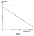
- the viscosity of the polymer and its gel time that is to say the time it takes to reach, as a result of the crosslinking reaction, a gelled state where it no longer flows, varies as a function of the temperature according to the curves of FIGS. 5 and 6 respectively, plotted in logarithmic coordinates.
- a temperature of 160 ° C corresponds to a viscosity of around 30 centipoise, allowing sufficient impregnation before the freezing time.
- the structure 19 is immersed in the polymer by moving the rod 20.
- the valve 23 is closed and a regulated pressure of 5 MPa of nitrogen is applied through a line 25 fitted with a valve 26.
- the temperature is raised again, at a speed of 2 ° C. per minute, up to 250 ° C, this temperature being maintained for 90 min.
- the autoclave is then cooled, then returned to the open air.
- the fibrous structure impregnated and coated with residual polymer easily detaches from the walls of the reservoir.
- the thermal cycle described above is deduced from the differential thermal analysis curves of FIG. 8, established for three different temperature rise rates.
- the temperature rise can be rapid (10 ° C per minute up to 200 ° C).
- the speed is reduced to 2 ° C per minute up to 250 ° C where a plateau is made.
- the pyrolysis of the polysilane is carried out in an oven with nitrogen sweeping according to the thermal cycle represented by the curve of FIG. 7, as established according to the thermogravimetric analysis curves of FIG. 1, so as to avoid too high an instantaneous mass loss rate, which would create mechanical stresses in the product.
- the temperature was raised to approximately 1150 ° C. over a period of 34 hours, at a variable speed such that the material flow rate is substantially constant and equal to 1% / h relative to the mass of the polymer. reticle. This duration could be reduced to 24 hours, the maximum treatment temperature being at least 1000 ° C.
- FIG. 9 represents three thermal analysis curves of the polysilane, a differential thermal analysis curve, a thermogravimetric analysis curve and a derived thermogravimetric analysis curve, plotted respectively in short dashed line, in broken line and in solid line .
- a first peak corresponding to crosslinking we find a first peak corresponding to crosslinking and a second peak corresponding to pyrolysis.
- the percentages of residual mass are indicated after the crosslinking peak (98% at 300 ° C) and after the pyrolysis peak (64% around 700 ° C). It can be seen in particular that the crosslinking takes place practically without loss of mass.
- the silicon carbide obtained is its chemical composition.
- the silicon carbide obtained by pyrolysis of a polysilane is not pure. It contains a little oxygen in addition to silicon and carbon.
- This carbon content can be modulated by playing on the formula of the starting monomer mixture.
- Example 3 the duration of the deposition in the second phase is increased to 120 min, leading to a carbon thickness of 500 to 700 nanometers. This results in poor impregnation in liquid polysilane due to bridging between the coatings of the different fibers.
- the residual porosity is high and the apparent density of the final product is low compared to those obtained with a carbon thickness of 200 to 300 nanometers (examples 4 to 6), produced with a deposition time of 70 min.
- the thickness of the filtration mold is greater than in example 4 (6.5 mm instead of 5.5), which leads to an apparent density d c and to an apparent density of the higher end product.
- Example 6 The apparent density d c is further improved in Example 6, compared with Example 5, by using an acetone slip. However, the properties of the final product are not significantly different.
- Examples 7 to 9 are the subject of Table 2, in which we find some of the characteristics explained with regard to Table 1.
- An aqueous slip is used in these three examples.
- Example 7 the fiber fabric is bidirectional.
- the porosity in the pyrolyzed state is lower than that of Example 5, for an equivalent apparent density.
- the mechanical properties are substantially proportional to the volume ratio of fibers used for these two examples.
- Example 8 we start from a unidirectional fibrous structure, which further decreases the porosity in the pyrolyzed state and increases the apparent density.
- the mechanical properties are slightly lower, compared to the rate of fibers used.
- Example 9 is a comparative example in which no fibrous structure is used, the slip being filtered moreover under the same conditions as in the previous examples. Porosity in the pyrolyzed state and an apparent density are obtained which are very close to those of Example 8, indicating that the unidirectional fibrous structure allows the production of a matrix having substantially optimal properties.
- the invention is not limited to the production of SiC-SiC composite materials.
- long fibers can be replaced by short fibers, possibly mixed with the ceramic powder before establishment of the fibrous structure.
- this powder can be introduced as a mixture with the liquid precursor into a fabric of fibers, the assembly then being heat treated under load.
Landscapes
- Chemical & Material Sciences (AREA)
- Engineering & Computer Science (AREA)
- Ceramic Engineering (AREA)
- Materials Engineering (AREA)
- Structural Engineering (AREA)
- Organic Chemistry (AREA)
- Manufacturing & Machinery (AREA)
- Inorganic Chemistry (AREA)
- Chemical Kinetics & Catalysis (AREA)
- Ceramic Products (AREA)
- Compositions Of Oxide Ceramics (AREA)
- Manufacture Of Alloys Or Alloy Compounds (AREA)
Claims (13)
- Verfahren zum Herstellen eines keramischen Verbundwerkstoffs, der eine Faserstruktur aus Siliciumcarbid aufweist, die in eine Matrix eingebettet ist, wobei man in die Hohlräume der Faserstruktur einerseits diskrete Partikel aus keramischem Material, andererseits eine flüssige Substanz einführt, die geeignet ist, durch thermische Behandlung in keramisches Material überführt zu werden, und man die Anordnung erhitzt, um die genannte Substanz zu überführen und die diskreten Partikel durch das so erhaltene keramische Material miteinander zu verbinden, indem eine durchgehende Matrix erzeugt wird, dadurch gekennzeichnet, daß die Matrix aus Siliciumcarbid besteht und die genannte flüssige Substanz ein flüssiges Polysilancopolymer ist, das bei Umgebungstemperatur geringe Viskosität aufweist und das thermisch härtbar ist und Ethylengruppen und Wasserstoffatome enthält, die an Siliciumatome gebunden sind, um nach Vernetzung in Siliciumcarbid umgewandelt zu werden, wobei dieses Polysilan erhalten wird, indem man zwei Monomere der folgenden Formeln miteinander reagieren läßt:
r(CR'₂=CR')SiX₂ (I)
RHSiX₂ (II)
wobei die Symbole R identische oder unterschiedliche Kohlenwasserstoffradikale darstellen, die Symbole X identische oder unterschiedliche Halogenatome darstellen und die Symbole R' jeweils ein Wasserstoffatom oder ein Kohlenwasserstoffradikal repräsentieren, und wenigstens ein Monohalogenid-Monomer mit in einem organischen Lösungsmittel in Form einer Mischung aus im wesentlichen Toluol und Dioxan geschmolzenem Natrium, wobei das Verhältnis r₁ der Anzahl der Mole des Monomeren (I) zur Anzahl der Mole des Monomeren (II) zwischen etwa 2 und etwa 3,3 liegt und das Verhältnis r₂ der Anzahl der Mole und des Monohalogenmonomeren zur Anzahl der Mole der Monomeren (I) und (II) zwischen etwa 0,2 und etwa 0,8 liegt, wobei die aus der Polimerisationsreaktion resultierende, wieder abgekühlte Mischung, die hauptsächlich Polysilan, Natriumrest, Natriumhalogenid und das Lösungsmittel enthält, durch Filtration in flüssiger Phase, die das Lösungsmittel und die Hauptfraktion kleiner Molokularmasse des Polysilans in flüssigem und/oder gelöstem Zustand und eine feste Phase, die das Natrium, das Natriumhologenid und ggf. die Fraktion höherer Molokularmasse des Polysilans enthält, abgetrennt wird, wobei das Polysilan aus der flüssigen Phase wiedergewonnen wird und die feste Phase bearbeitet wird, um das Restnatrium zu oxidieren. - Verfahren nach Anspruch 1, dadurch gekennzeichnet, daß man über die vorgefertigte Faserstruktur (6) eine Suspension (9) aus Keramikmaterialpartikeln in einem flüssigen Träger bis zur Einführung des gewünschten Partikelvolumens in die Hohlräume der Struktur passieren läßt, daß man den flüssigen, in den Hohlräumen vorhandenen Träger beseitigt und man dann das flüssige Polysilan (21) in das von den Partikeln zurückgelassene freie Volumen einleitet.
- Verfahren nach Anspruch 2, dadurch gekennzeichnet, daß man die in der Faserstruktur vorhandenen Siliciumcarbidpartikel vor der Einleitung des flüssigen Polysilans einer Behandlung unterwirft, die ihre Benetzbarkeit verbessert.
- Verfahren nach Anspruch 3, dadurch gekennzeichnet, daß man die an der Oberfläche der Partikel vorhandenen Hydroxylgruppen durch Einwirkung eines monohalogenierten Monosilans in gasförmigem Zustand beseitigt.
- Verfahren nach einem der vorhergehenden Ansprüche, dadurch gekennzeichnet, daß man das flüssige Polysilan durch Immersion der mit den Keramikpartikeln versetzten Faserstruktur (9) in ein Polysilanbad (21) einführt.
- Verfahren nach einem der vorhergehenden Ansprüche, dadurch gekennzeichnet, daß die Faserstruktur lange Fasern enthält, die sich in wenigstens einer Richtung durchgehend erstrecken.
- Verfahren nach Anspruch 6, dadurch gekennzeichnet, daß man die Fasern vor ihrer Inberührungbringung mit den Siliciumcarbidpartikeln und dem flüssigen Polysilan einer Behandlung unterwirft, die die physikalisch-chemischen Wechselwirkungen zwischen den Fasern und der Matrix einschränkt.
- Verfahren nach Anspruch 7, dadurch gekennzeichnet, daß die Behandlung, die die Wechselwirkungen einschränkt, eine Einbringung eines Einlagematerials mit anisotroper interner Kohesion ist.
- Verfahren nach Anspruch 8, dadurch gekennzeichnet, daß das Einlagematerial Kohlenstoff ist.
- Verfahren nach einem der vorhergehenden Ansprüche, dadurch gekennzeichnet, daß die für Herstellung des Polysilans und ihrer betreffenden molaren Fraktionen verwendeten Monomere die folgenden sind:
CH₃(CH₂=CH)SiCl₂ 0,76 CH₃HSiCl₂ 0,24 (CH₃)₃SiCl 0,40 - Verfahren nach einem der vorhergehenden Ansprüche, dadurch gekennzeichnet, daß das Polysilan eine Viskosität hat, die bei Umgebungstemperatur eine Viskosität unter 20 Poise und bei 100°C eine Viskosität von weniger als 1 Poise hat.
- Verfahren nach einem der vorhergehenden Ansprüche, dadurch gekennzeichnet, daß das Polysilan bei einer Temperatur von etwa 1000°C behandelt wird, um das Siliciumcarbid zu erhalten.
- Verfahren nach einem der vorhergehenden Ansprüche, dadurch gekennzeichnet, daß der Umwandlungsbehandlung des Polysilans in Siliciumcarbid eine Vernetzungsbehandlung bei tieferer Temperatur vorangeht.
Applications Claiming Priority (2)
| Application Number | Priority Date | Filing Date | Title |
|---|---|---|---|
| FR8916918A FR2655977B1 (fr) | 1989-12-20 | 1989-12-20 | Procede d'elaboration d'un materiau composite ceramique fibres-matrice, et materiau composite obtenu par ce procede. |
| FR8916918 | 1989-12-20 |
Publications (2)
| Publication Number | Publication Date |
|---|---|
| EP0434501A1 EP0434501A1 (de) | 1991-06-26 |
| EP0434501B1 true EP0434501B1 (de) | 1995-11-15 |
Family
ID=9388773
Family Applications (1)
| Application Number | Title | Priority Date | Filing Date |
|---|---|---|---|
| EP90403533A Expired - Lifetime EP0434501B1 (de) | 1989-12-20 | 1990-12-11 | Verfahren zur Herstellung eines fasermatrix-keramischen Verbundwerkstoffs |
Country Status (6)
| Country | Link |
|---|---|
| US (1) | US5196235A (de) |
| EP (1) | EP0434501B1 (de) |
| JP (1) | JP2529135B2 (de) |
| CA (1) | CA2032666C (de) |
| DE (1) | DE69023620T2 (de) |
| FR (1) | FR2655977B1 (de) |
Families Citing this family (18)
| Publication number | Priority date | Publication date | Assignee | Title |
|---|---|---|---|---|
| US5439627A (en) * | 1990-06-29 | 1995-08-08 | Flexline Services Ltd. | Process for manufacturing reinforced composites |
| FR2677641B1 (fr) * | 1991-06-17 | 1994-01-28 | Propulsion Ste Europeenne | Procede d'elaboration de pieces en materiau composite a matrice alumine. |
| JPH0784344B2 (ja) * | 1991-11-20 | 1995-09-13 | 工業技術院長 | 炭素繊維強化炭化ケイ素複合セラミックスの製造方法 |
| US5241029A (en) * | 1992-01-07 | 1993-08-31 | Iowa State University Research Foundation, Inc. | Diorganosilacetylene-alt-diorganosilvinylene polymers and a process of preparation |
| FR2712285B1 (fr) * | 1993-11-12 | 1995-12-22 | Lorraine Carbone | Traitement de surface de matériau carbone pour rendre adhérent un dépôt ultérieur de diamant et pièces revêtues de diamant obtenues. |
| DE69524432T2 (de) * | 1994-09-12 | 2002-08-01 | Kabushiki Kaisha Toshiba, Kawasaki | Faserverbundkörper auf keramikbasis |
| US5856252A (en) * | 1995-06-07 | 1999-01-05 | The Regents Of The University Of California | Damage tolerant ceramic matrix composites by a precursor infiltration |
| EP0933343B1 (de) * | 1998-01-29 | 2003-06-25 | Coi Ceramics, Inc. | Verfahren zur Herstellung von geschlichteten beschichteten keramischen Fasern |
| JP3722188B2 (ja) | 1999-01-28 | 2005-11-30 | 石川島播磨重工業株式会社 | セラミックス基複合部材及びその製造方法 |
| EP1359132A1 (de) * | 2002-04-30 | 2003-11-05 | European Community | Verbundwerkstoffe, Anwendungen, und Verfahren zur Herstellung der genannten Verbundwerkstoffe |
| AT412208B (de) * | 2003-03-11 | 2004-11-25 | Arc Seibersdorf Res Gmbh | Verbundwerkstoff und verfahren zu dessen herstellung |
| ES2384356T3 (es) | 2008-10-31 | 2012-07-04 | Avio S.P.A. | Método para la producción de componentes hechos de material compuesto de matriz cerámica |
| US9944564B2 (en) | 2013-10-30 | 2018-04-17 | United Technologies Corporation | Ceramic article and method therefor using particle infiltration and preceramic polymer infiltration |
| CN106319934B (zh) * | 2015-06-30 | 2019-02-15 | 中国人民解放军国防科学技术大学 | 碳化硅纳米线原位增强的碳化硅纤维材料及其制备方法 |
| US10052789B2 (en) * | 2015-11-25 | 2018-08-21 | General Electric Company | Methods of processing ceramic fiber |
| US9815736B2 (en) * | 2015-11-25 | 2017-11-14 | General Electric Company | Apparatus and methods for processing ceramic fiber |
| US10472713B2 (en) * | 2016-05-31 | 2019-11-12 | United Technologies Corporation | Method for ceramic matrix composite with carbon coating for wetting |
| CN120794662A (zh) * | 2025-08-16 | 2025-10-17 | 濮阳市盛源东辰科技有限公司 | 快速制备陶瓷基复合材料的方法及陶瓷基复合材料 |
Family Cites Families (9)
| Publication number | Priority date | Publication date | Assignee | Title |
|---|---|---|---|---|
| FR2401888A1 (fr) * | 1977-09-06 | 1979-03-30 | Europ Propulsion | Piece poreuse carbonee densifiee in situ par depot chimique en phase vapeur de materiaux refractaires autres que le carbone et procede de fabrication |
| CA1180169A (en) * | 1982-01-25 | 1985-01-02 | Toshikatsu Ishikawa | Process for the preparation of sintered bodies |
| FR2520730B1 (fr) * | 1982-02-03 | 1990-10-26 | Nippon Carbon Co Ltd | Procede de preparation de corps frittes mettant en oeuvre un compose organosilicie |
| US4783516A (en) * | 1983-03-31 | 1988-11-08 | Union Carbide Corporation | Polysilane precursors containing olefinic groups for silicon carbide |
| FR2547577B1 (fr) * | 1983-06-20 | 1989-12-15 | Aerospatiale | Matiere refractaire composite renforcee de fibres refractaires et son procede de fabrication |
| JPS61247663A (ja) * | 1985-04-22 | 1986-11-04 | 工業技術院長 | 炭素連続繊維強化SiC複合体の製造方法 |
| JPS62227702A (ja) * | 1986-03-31 | 1987-10-06 | アイシン精機株式会社 | 強化型セラミツクスの製造方法 |
| JPH01112523A (ja) * | 1987-10-24 | 1989-05-01 | Hitachi Maxell Ltd | 磁気記録媒体 |
| EP0334577A1 (de) * | 1988-03-21 | 1989-09-27 | Hoechst Celanese Corporation | Kohlenstoff-Beschichtung von Siliciumcarbid-Fasern zum Kontrollieren von Oxid-Überzügen |
-
1989
- 1989-12-20 FR FR8916918A patent/FR2655977B1/fr not_active Expired - Fee Related
-
1990
- 1990-12-11 EP EP90403533A patent/EP0434501B1/de not_active Expired - Lifetime
- 1990-12-11 DE DE69023620T patent/DE69023620T2/de not_active Expired - Fee Related
- 1990-12-19 CA CA002032666A patent/CA2032666C/en not_active Expired - Fee Related
- 1990-12-19 US US07/629,945 patent/US5196235A/en not_active Expired - Lifetime
- 1990-12-20 JP JP2411943A patent/JP2529135B2/ja not_active Expired - Fee Related
Also Published As
| Publication number | Publication date |
|---|---|
| FR2655977B1 (fr) | 1993-07-09 |
| DE69023620D1 (de) | 1995-12-21 |
| CA2032666A1 (en) | 1991-06-21 |
| DE69023620T2 (de) | 1996-06-20 |
| JP2529135B2 (ja) | 1996-08-28 |
| FR2655977A1 (fr) | 1991-06-21 |
| US5196235A (en) | 1993-03-23 |
| JPH04228476A (ja) | 1992-08-18 |
| CA2032666C (en) | 1995-12-12 |
| EP0434501A1 (de) | 1991-06-26 |
Similar Documents
| Publication | Publication Date | Title |
|---|---|---|
| EP0434501B1 (de) | Verfahren zur Herstellung eines fasermatrix-keramischen Verbundwerkstoffs | |
| EP0495700B1 (de) | Verfahren zur Verdichtung eines porösen Substrats mittels einer kohlenstoffhaltigen Matrix | |
| EP0677029B1 (de) | Verfahren zur herstellung von gegenständen aus kohlenstoffsiliziumkarbid-verbundwerkstoff, und kohlenstoff-siliziumkarbid-verbundwerkstoff | |
| WO1996030317A1 (fr) | Materiau composite protege contre l'oxydation par matrice autocicatrisante et son procede de fabrication | |
| FR2649094A1 (fr) | Procede de production d'un article en materiau composite, compose essentiellement de fibres revetues de carbone dans une matrice de carbure de silicium | |
| EP0085601A1 (de) | Verfahren zur Herstellung einer Verbundstruktur von Feuerfest-Feurfest-Typ und so hergestellte Struktur | |
| FR2528823A1 (fr) | Procede de fabrication d'articles en carbone ou en graphite contenant du carbure de silicium lie par reaction | |
| EP0948469A1 (de) | Verbundwerkstoff mit keramischer matrix und vertärkung aus sic-fasern sowieverfahren zu seiner herstellung | |
| FR2732677A1 (fr) | Procede d'infiltration chimique en phase vapeur avec parametres d'infiltration variables | |
| FR2544661A1 (fr) | Materiaux composites constitues par une matrice en carbone coke de resine, renforcee par des fibres refractaires revetues de carbone pyrolytique, et procede pour leur obtention | |
| JP2000143368A (ja) | 多孔質構造物のcviによる緻密化 | |
| EP0555130B1 (de) | Verfahren zur Herstellung von Teilen aus Verbundwerkstoff mit keramischer Matrix | |
| EP0675861B1 (de) | Wärmedämmstoff aus kohlenstoff und sein herstellungsverfahren | |
| EP0373007B1 (de) | Multidirektionelle Texturen aus keramischen Fibern auf Basis von Silizium enthaltenden Zusammensetzungen, deren Herstellung und damit verstärkte Verbundkörper | |
| EP0633233B1 (de) | Verfahren zur Herstellung eines Verbundwerkstoffelements enthaltende eine auf flüssigem Wege erhaltene Faserverstärkung | |
| EP0078197B1 (de) | Keramische Verbundmaterialien mit hoher mechanischer und thermischer Beständigkeit und ihre Herstellung | |
| EP0672638B1 (de) | Thermisch isolierendes Material auf Basis von Aluminiumoxide-Fiber und seine Herstellung | |
| EP1888813B1 (de) | Verfahren zur schnellen verdichtung eines porösen fasersubstrats mit bildung einer festen ablage innerhalb der substratporosität | |
| FR2626269A1 (fr) | Materiau composite a base de carbone renforce par des fibres de carbone et procede de preparation de celui-ci | |
| EP0656329B1 (de) | Verfahren zur Herstellung von keramischen Werkstoffen durch impregnieren eines poreusen keramischen Trägers mit einem Vorläufer | |
| FR2692250A1 (fr) | Composite de carboxyde de silicium renforcé de fibres céramiques. | |
| FR3016361A1 (fr) | Comblement des macropores d'un substrat fibreux par du pyrocarbone | |
| FR2758146A1 (fr) | Materiau composite a renfort carbone dans une matrice mixte carbone-metal et son procede de fabrication |
Legal Events
| Date | Code | Title | Description |
|---|---|---|---|
| PUAI | Public reference made under article 153(3) epc to a published international application that has entered the european phase |
Free format text: ORIGINAL CODE: 0009012 |
|
| AK | Designated contracting states |
Kind code of ref document: A1 Designated state(s): CH DE FR GB IT LI NL SE |
|
| 17P | Request for examination filed |
Effective date: 19910916 |
|
| 17Q | First examination report despatched |
Effective date: 19930608 |
|
| GRAA | (expected) grant |
Free format text: ORIGINAL CODE: 0009210 |
|
| AK | Designated contracting states |
Kind code of ref document: B1 Designated state(s): CH DE FR GB IT LI NL SE |
|
| GBT | Gb: translation of ep patent filed (gb section 77(6)(a)/1977) |
Effective date: 19951114 |
|
| REF | Corresponds to: |
Ref document number: 69023620 Country of ref document: DE Date of ref document: 19951221 |
|
| ITF | It: translation for a ep patent filed | ||
| PGFP | Annual fee paid to national office [announced via postgrant information from national office to epo] |
Ref country code: NL Payment date: 19951230 Year of fee payment: 6 |
|
| PGFP | Annual fee paid to national office [announced via postgrant information from national office to epo] |
Ref country code: CH Payment date: 19960118 Year of fee payment: 6 |
|
| REG | Reference to a national code |
Ref country code: CH Ref legal event code: NV Representative=s name: PPS POLYVALENT PATENT SERVICE AG |
|
| PLBE | No opposition filed within time limit |
Free format text: ORIGINAL CODE: 0009261 |
|
| STAA | Information on the status of an ep patent application or granted ep patent |
Free format text: STATUS: NO OPPOSITION FILED WITHIN TIME LIMIT |
|
| 26N | No opposition filed | ||
| PG25 | Lapsed in a contracting state [announced via postgrant information from national office to epo] |
Ref country code: CH Effective date: 19961231 Ref country code: LI Effective date: 19961231 |
|
| PG25 | Lapsed in a contracting state [announced via postgrant information from national office to epo] |
Ref country code: NL Effective date: 19970701 |
|
| REG | Reference to a national code |
Ref country code: CH Ref legal event code: PL |
|
| NLV4 | Nl: lapsed or anulled due to non-payment of the annual fee |
Effective date: 19970701 |
|
| REG | Reference to a national code |
Ref country code: GB Ref legal event code: IF02 |
|
| PG25 | Lapsed in a contracting state [announced via postgrant information from national office to epo] |
Ref country code: IT Free format text: LAPSE BECAUSE OF NON-PAYMENT OF DUE FEES;WARNING: LAPSES OF ITALIAN PATENTS WITH EFFECTIVE DATE BEFORE 2007 MAY HAVE OCCURRED AT ANY TIME BEFORE 2007. THE CORRECT EFFECTIVE DATE MAY BE DIFFERENT FROM THE ONE RECORDED. Effective date: 20051211 |
|
| PGFP | Annual fee paid to national office [announced via postgrant information from national office to epo] |
Ref country code: DE Payment date: 20070130 Year of fee payment: 17 |
|
| PGFP | Annual fee paid to national office [announced via postgrant information from national office to epo] |
Ref country code: SE Payment date: 20071212 Year of fee payment: 18 |
|
| PGFP | Annual fee paid to national office [announced via postgrant information from national office to epo] |
Ref country code: GB Payment date: 20071207 Year of fee payment: 18 Ref country code: FR Payment date: 20071207 Year of fee payment: 18 |
|
| PG25 | Lapsed in a contracting state [announced via postgrant information from national office to epo] |
Ref country code: DE Free format text: LAPSE BECAUSE OF NON-PAYMENT OF DUE FEES Effective date: 20080701 |
|
| EUG | Se: european patent has lapsed | ||
| GBPC | Gb: european patent ceased through non-payment of renewal fee |
Effective date: 20081211 |
|
| REG | Reference to a national code |
Ref country code: FR Ref legal event code: ST Effective date: 20090831 |
|
| PG25 | Lapsed in a contracting state [announced via postgrant information from national office to epo] |
Ref country code: GB Free format text: LAPSE BECAUSE OF NON-PAYMENT OF DUE FEES Effective date: 20081211 |
|
| PG25 | Lapsed in a contracting state [announced via postgrant information from national office to epo] |
Ref country code: FR Free format text: LAPSE BECAUSE OF NON-PAYMENT OF DUE FEES Effective date: 20081231 |
|
| PG25 | Lapsed in a contracting state [announced via postgrant information from national office to epo] |
Ref country code: SE Free format text: LAPSE BECAUSE OF NON-PAYMENT OF DUE FEES Effective date: 20081212 |