EP0433601B1 - Hydraulic toggle lever device - Google Patents
Hydraulic toggle lever device Download PDFInfo
- Publication number
- EP0433601B1 EP0433601B1 EP19900120066 EP90120066A EP0433601B1 EP 0433601 B1 EP0433601 B1 EP 0433601B1 EP 19900120066 EP19900120066 EP 19900120066 EP 90120066 A EP90120066 A EP 90120066A EP 0433601 B1 EP0433601 B1 EP 0433601B1
- Authority
- EP
- European Patent Office
- Prior art keywords
- toggle lever
- piston rod
- housing
- swivel
- pin
- Prior art date
- Legal status (The legal status is an assumption and is not a legal conclusion. Google has not performed a legal analysis and makes no representation as to the accuracy of the status listed.)
- Expired - Lifetime
Links
Images
Classifications
-
- B—PERFORMING OPERATIONS; TRANSPORTING
- B25—HAND TOOLS; PORTABLE POWER-DRIVEN TOOLS; MANIPULATORS
- B25B—TOOLS OR BENCH DEVICES NOT OTHERWISE PROVIDED FOR, FOR FASTENING, CONNECTING, DISENGAGING OR HOLDING
- B25B5/00—Clamps
- B25B5/06—Arrangements for positively actuating jaws
- B25B5/12—Arrangements for positively actuating jaws using toggle links
- B25B5/122—Arrangements for positively actuating jaws using toggle links with fluid drive
Definitions
- the invention relates to a pressure medium-operated toggle lever tensioning device according to the preamble of patent claim 1.
- Such a toggle lever tensioning device is previously known from DE-AS 22 22 686.
- a support plate in particular transport trolley or pallet support plate, is already known, with a clamping device for objects that can be clamped on the plate, the clamping device having a clamping lever as a connecting link between two rockers and forming a quadrilateral joint with them, with its clamping part the joint which projects above a rocker and an adjusting drive element is arranged on the four-bar linkage.
- the support plate is provided with a through-opening arranged in the adjustment path of the tensioning lever, the tensioning device being arranged under the support plate and the tensioning of the tensioning lever being in the form of a hook, the joints of the four-bar linkage being arranged in this way and the wings are dimensioned in such a way that the tensioning lever in the tensioned position extends through the passage opening with its longitudinal axis transverse to its course when the tensioning lever is reset under the support plate.
- the drive member of the four-bar linkage is designed in the form of a toggle lever drive.
- a clamping tool is known with a back and forth in guides on a support, actuated by a drive pressure block, and a clamping arm articulated via a fixed pivot on the support with an inclined operating slot extending from the movement path of the pressure block , with which the pressure block slidably cooperates in order to pivot and clamp the clamping arm.
- the actuating slot contains a first leg that is more inclined to the path of movement of the printing block, and a second leg that is inclined less to the path of movement of the printing block.
- a gripping device in which a collet is moved back and forth by a piston-cylinder unit which is acted upon alternately on both sides by pressure.
- the tensioning arm is arranged so as to be pivotable via a tab on a bolt fixed to the housing and at a distance from it by a second bolt on the housing.
- a clamping device in particular for clamping workpieces, which has a lifting cylinder with clamping iron arranged on a base plate, the lifting cylinder being pivoted at one end to the base plate, while the other end is a guide device, preferably has guide pins which are guided through fixed curved guide tracks.
- the invention has for its object to improve a toggle lever clamping device of the prerequisite type in such a way that it can also be used as a base clamp.
- this toggle lever tensioning device is made usable as a base clamp, so that the tensioning hook can be moved completely into the space of the housing in which the toggle joint arrangement is also located and which is connected to the free atmosphere.
- This tensioning hook is moved in the tightest of spaces and precisely guided by a guide. This also results in a stable articulation and guidance of the tensioning hook.
- the tensioning hook can always be moved exactly on its predetermined path without the need for many joints and link elements.
- the tensioning hook itself emerges through an opening in the upper plate of the housing if it is to be brought into the tensioned position.
- Claim 3 describes a particularly advantageous embodiment in which the housing consists in one piece of material from a casting and
- the cylinder for the toggle lever tensioning device can be integrally connected in terms of material or functionally in one piece in some other way.
- the upper plate of the casting simultaneously forms a mounting plate and can have suitable bores or holes for this, which also applies to the plate opposite this plate.
- the housing closes the toggle joint arrangement and the link support relatively dirt and dust-tight. In any case, it protects these parts from direct impact and shock loads (claim 3).
- the reference numeral 1 designates a housing-like cylinder in which a piston 2 is guided in a cylinder space 3 so as to be longitudinally displaceable and sealingly by seals (not shown).
- Pressure medium in particular air pressure, is supplied to the cylinder chamber 3 through connection channels 4 or 5, whereby the piston 2 is to be acted upon alternately on both sides with pressure medium pressure.
- a piston rod 6 is integrally connected to the piston 2 and is sealed in the region of a collar 7 by sealing means, not shown.
- the piston rod 6 exits into a movement space 8 which is connected to the free atmosphere or an ambient space via an opening 9 of large cross section.
- the movement space 8 is enclosed by a housing 10 which, in the embodiment shown, is made in one piece from cast material and is either integral with the cylinder 1 or functionally connected. The latter is not shown.
- a toggle joint arrangement 11 Arranged in the movement space 8 is a toggle joint arrangement 11, which is assigned at least one bracket 12, which is pivotally connected to the piston rod 6 via a piston rod pin 13.
- the piston rod pin 13 is arranged orthogonal to the longitudinal axis of the piston rod 6 and carries a roller 14 and 15 at each end.
- Each of the rollers 14 and 15 is guided in a guide groove 16 and 17, respectively.
- the guide grooves 16 and 17 run parallel to each other and parallel to the longitudinal axis of the piston rod 6 and are part of the housing 10 and incorporated into this.
- the piston rod pin 13 is guided in the housing 10 with relatively little friction, which also has advantages when the toggle joint arrangement 11 is driven over dead center.
- the tab 12 is pivotally coupled at its end via a stationary toggle joint axis 18 to a rocker 19 which is arranged in the housing 10 so as to be pivotable about an axis 20 fixed to the housing.
- a two-armed lever 21 is pivotally connected to the axis 18, which is arranged pivotably in the direction C or D and which can be pivoted completely into the movement space 8 from the tensioned position from FIG. 1 into the release position according to FIG. 2.
- the two-armed lever 21 is guided by a pivot pin 22 in a link slot 23, the longitudinal axis of which extends approximately at 45 ° to the longitudinal axis of the piston rod 6.
- the pivot pin 22 can be provided at its ends with at least one roller for low-friction guidance.
- the link slot 23 can only be provided on one side of the housing 10. However, it is also possible to arrange the link slots in pairs on opposite sides of the housing and to guide the pivot pin 22 at its opposite end through a roller in the associated link slot.
- an end stop is arranged, which is adjustable by a screw 25.
- inductive proximity switches or the like can also be assigned to the piston 2. It is also possible to change the shape of the two-armed lever 21 as required. As can be seen, the two-armed lever 21 describes a relatively narrow circular arc, so that it is arranged in a protected manner in the movement space 8 in the release position.
- the upper plate 26 can be provided with one or more bores for fastening the toggle lever tensioning device, although this is not shown. This also applies to the side plate 27 and the base plate 28.
Description
Die Erfindung betrifft eine druckmittelbetätigbare Kniehebelspannvorrichtung nach dem Oberbegriff des Patentanspruches 1.The invention relates to a pressure medium-operated toggle lever tensioning device according to the preamble of
Eine derartige Kniehebelspannvorrichtung ist aus der DE-AS 22 22 686 vorbekannt.Such a toggle lever tensioning device is previously known from DE-AS 22 22 686.
Aus der DE-PS 34 19 878 ist eine Tragplatte, insbesondere Transportwagenoder Palettentragplatte, vorbekannt, mit einer Spannvorrichtung für auf der Platte festspannbare Gegenstände, wobei die Spannvorrichtung einen Spannhebel als Verbindungsglied zweier Schwingen aufweist und mit diesen ein Gelenkviereck bildet, mit seinem Spannteil das Gelenk der einen Schwinge überragt und am Gelenkviereck ein Verstellantriebsglied angeordnet ist. Die Tragplatte ist mit einer im Stellweg des Spannhebel angeordneten Durchgriffsöffnung versehen, wobei die Spannvorrichtung unter der Tragplatte angeordnet ist und das Spannte des Spannhebels in Form eines Hakens ausgebildet ist, wobei die Gelenke des Gelenkvierecks derart angeordnet und die Schwingen derart bemessen sind, daß der Spannhebel in Spannstellung die Durchgriffsöffnung durchgreifend mit seiner Längsachse quer zu deren Verlauf bei Rückzustellung des Spannhebels unter der Tragplatte steht. Das Antriebsglied des Gelenkvierecks ist in Form eines Kniehebelantriebes ausgebildet.From DE-PS 34 19 878 a support plate, in particular transport trolley or pallet support plate, is already known, with a clamping device for objects that can be clamped on the plate, the clamping device having a clamping lever as a connecting link between two rockers and forming a quadrilateral joint with them, with its clamping part the joint which projects above a rocker and an adjusting drive element is arranged on the four-bar linkage. The support plate is provided with a through-opening arranged in the adjustment path of the tensioning lever, the tensioning device being arranged under the support plate and the tensioning of the tensioning lever being in the form of a hook, the joints of the four-bar linkage being arranged in this way and the wings are dimensioned in such a way that the tensioning lever in the tensioned position extends through the passage opening with its longitudinal axis transverse to its course when the tensioning lever is reset under the support plate. The drive member of the four-bar linkage is designed in the form of a toggle lever drive.
Aus der DE-AS 19 50 721 ist ein Spannwerkzeug mit einem in Führungen an einem Träger hin- und hergehend gelagerten, von einem Antrieb betätigbaren Druckblock und einem über einen festen Drehzapfen am Träger angelenkten Spannarm mit einem geneigt von der Bewegungsbahn des Druckblocks verlaufenden Betätigungsschlitz vorbekannt, mit dem der Druckblock zwecks Verschwenken und Festklemmen des Spannarms verschiebbar zusammenwirkt. Der Betätigungsschlitz enthält einen ersten, zur Bewegungsbahn des Druckblocks stärker geneigten Schenkel, und einen zweiten, zur Bewegungsbahn des Druckblocks schwächer geneigten Schenkel.From DE-AS 19 50 721 a clamping tool is known with a back and forth in guides on a support, actuated by a drive pressure block, and a clamping arm articulated via a fixed pivot on the support with an inclined operating slot extending from the movement path of the pressure block , with which the pressure block slidably cooperates in order to pivot and clamp the clamping arm. The actuating slot contains a first leg that is more inclined to the path of movement of the printing block, and a second leg that is inclined less to the path of movement of the printing block.
Aus der US 35 45 050 ist ein Spannzeug bekannt, bei welchem eine Spannzange durch eine abwechselnd beidseitig durch Druck beaufschlagte Kolbenzylinder-Einheit hin- und herbewegt wird. Der Spannarm ist über eine Lasche an einem gehäusefesten Bolzen und im Abstand dazu durch einen zweiten Bolzen am Gehäuse schwenkbeweglich angeordnet.From US 35 45 050 a gripping device is known in which a collet is moved back and forth by a piston-cylinder unit which is acted upon alternately on both sides by pressure. The tensioning arm is arranged so as to be pivotable via a tab on a bolt fixed to the housing and at a distance from it by a second bolt on the housing.
Aus der DD-PS 60 527 ist eine Spannvorrichtung, insbesondere zum Spannen von Werkstücken, vorbekannt, die einen auf einer Grundplatte angeordneten Hubzylinder mit Spanneisen aufweist, wobei der Hubzylinder mit einem Ende schwenkbar an der Grundplatte angelenkt ist, während das andere Ende eine Führungseinrichtung, vorzugsweise Führungsstifte, aufweist, die durch feststehende kurvenförmige Führungsbahnen geführt sind.From DD-PS 60 527, a clamping device, in particular for clamping workpieces, is known which has a lifting cylinder with clamping iron arranged on a base plate, the lifting cylinder being pivoted at one end to the base plate, while the other end is a guide device, preferably has guide pins which are guided through fixed curved guide tracks.
Der Erfindung liegt die Aufgabe zugrunde, eine Kniehebelspannvorrichtung der vorausgesetzten Gattung dahingehend zu verbessern, daß sie auch als Unterbauspanner verwendbar ist.The invention has for its object to improve a toggle lever clamping device of the prerequisite type in such a way that it can also be used as a base clamp.
Ausgehend von einer Kniehebelspannvorrichtung der vorausgesetzten Art wird diese Aufgabe durch die in Patentanspruch 1 wiedergegebenen Merkmale gelöst.Starting from a toggle lever tensioning device of the required type, this object is achieved by the features set out in
Bei Ausgestaltung einer Kniehebelspannvorrichtung gemäß der Erfindung ergibt sich der Vorteil, daß die vorteilhafte Kniehebelspannvorrichtung der vorausgesetzten Art prinzipiell nicht konstruktiv verändert zu werden braucht.When designing a toggle lever tensioning device according to the invention, there is the advantage that the advantageous toggle lever tensioning device of the type assumed does not in principle need to be changed in terms of construction.
Durch die besondere Ausgestaltung der Erfindung wird diese Kniehebelspannvorrichtung aber als Unterbauspanner verwendungsfähig gemacht, so daß der Spannhaken vollkommen in den Raum des Gehäuses einzufahren ist, in dem sich auch die Kniehebelgelenkanordnung befindet und der an die freie Atmosphäre angeschlossen ist. Dabei wird dieser Spannhaken auf engstem Raum bewegt und durch eine Kulissenführung präzise geführt. Dadurch ergibt sich auch eine stabile Anlenkung und Führung des Spannhakens. Infolgedessen läßt sich der Spannhaken immer genau auf seiner vorbestimmten Bahn bewegen, ohne daß viele Gelenke und Lenkerelemente erforderlich sind. Der Spannhaken selbst tritt durch eine Öffnung an der oberen Platte des Gehäuses heraus, falls er in Spannstellung gebracht werden soll.Due to the special embodiment of the invention, this toggle lever tensioning device is made usable as a base clamp, so that the tensioning hook can be moved completely into the space of the housing in which the toggle joint arrangement is also located and which is connected to the free atmosphere. This tensioning hook is moved in the tightest of spaces and precisely guided by a guide. This also results in a stable articulation and guidance of the tensioning hook. As a result, the tensioning hook can always be moved exactly on its predetermined path without the need for many joints and link elements. The tensioning hook itself emerges through an opening in the upper plate of the housing if it is to be brought into the tensioned position.
Zwar ist eine sogenannte "Tragplatte" durch die DE-PS 34 19 878 vorbekannt, jedoch weist diese Konstruktion eine ungünstige Anhäufung von Lenkerelementen, Gelenkpunkten und Schwenkachsen auf, die alle dem Verschleiß unterliegen, so daß die Gelenkanordnung - besonders nach einer entsprechend hohen Lastspielzeit - zum Schlackern neigt.Although a so-called " support plate" is previously known from DE-PS 34 19 878, this construction has an unfavorable accumulation of handlebar elements, pivot points and pivot axes, all of which are subject to wear, so that the joint arrangement - especially after a correspondingly high load cycle - tends to slag.
Patentanspruch 3 beschreibt eine besonders vorteilhafte Ausführungsform, bei welcher das Gehäuse materialmäßig einstückig aus einem Gußteil besteht und zum Beispiel mit dem Zylinder für die Kniehebelspannvorrichtung materialmäßig einstückig oder in sonstiger Weise funktionell einstückig verbunden sein kann. Die obere Platte des Gußteils bildet gleichzeitig eine Montageplatte und kann hierfür geeignete Bohrungen oder Löcher aufweisen, was auch für die dieser Platte gegenüberliegende Platte gilt. Das Gehäuse schließt die Kniehebelgelenkanordnung und die Kulissenförderung relativ schmutz- und staubdicht ab. Auf jeden Fall schützt sie diese Teile vor direkter Schlag- und Stoßbeanspruchung (Patentanspruch 3).
In den Patentansprüchen 4 und 5 sind weitere vorteilhafte Ausführungsformen der Erfindung beschrieben.
In der Zeichnung ist die Erfindung - teils schematisch - an einem Ausführungsbeispiel veranschaulicht. Es zeigt:
- Fig. 1
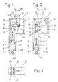
- eine Kniehebelspannvorrichtung gemäß der Erfindung im Längsschnitt, teils in der Ansicht bei in Spannstellung gefahrenem Spannhaken und Übertotpunktlage der Kniehebelgelenkanordnung;
- Fig. 2
- die aus Fig. 1 ersichtliche Kniehebelspannvorrichtung, allerdings in Lösestellung, wobei der Spannhaken vollkommen in das Gehäuse eingefahren ist, und
- Fig. 3
- eine Teildraufsicht zu Fig. 1.
- Fig. 1
- a toggle lever tensioning device according to the invention in longitudinal section, partly in view with the tensioning hook moved in the tensioned position and the dead center position of the toggle lever joint arrangement;
- Fig. 2
- the knee lever clamping device shown in Fig. 1, but in the release position, wherein the clamping hook is completely retracted into the housing, and
- Fig. 3
- 2 shows a partial top view of FIG. 1.
Mit dem Bezugszeichen 1 ist ein gehäuseartiger Zylinder bezeichnet, in dem ein Kolben 2 durch nicht dargestellte Dichtungen längsverschieblich und dichtend in Richtung A bzw. B in einem Zylinderraum 3 verschieblich geführt ist. Dem Zylinderraum 3 wird durch Anschlußkanäle 4 bzw. 5 Druckmittel, insbesondere Luftdruck, zugeführt, wodurch der Kolben 2 abwechselnd beidseitig mit Druckmitteldruck zu beaufschlagen ist.The
Mit dem Kolben 2 ist eine Kolbenstange 6 einstückig verbunden, die im Bereich eines Kragens 7 durch nicht dargestellte Dichtungsmittel abgedichtet ist. Die Kolbenstange 6 tritt in einen Bewegungsraum 8 aus, der über eine Öffnung 9 großen Querschnittes an die freie Atmosphäre oder einen Umgebungsraum angeschlossen ist.A
Der Bewegungsraum 8 wird von einem Gehäuse 10 umschlossen, das bei der dargestellten Ausführungsform materialmäßig einstückig aus Guß besteht und entweder mit dem Zylinder 1 materialmäßig einstückig oder funktionell verbunden ist. Letzteres ist nicht dargestellt.The
In dem Bewegungsraum 8 ist eine Kniehebelgelenkanordnung 11 angeordnet, der mindestens eine Lasche 12 zugeordnet ist, die über einen Kolbenstangenbolzen 13 mit der Kolbenstange 6 schwenkbeweglich verbunden ist. Der Kolbenstangenbolzen 13 ist orthogonal zur Längsachse der Kolbenstange 6 angeordnet und trägt an jedem Ende eine Rolle 14 bzw. 15. Jede der Rollen 14 und 15 ist in einer Führungsnut 16 bzw. 17 geführt. Die Führungsnuten 16 und 17 verlaufen parallel zueinander und parallel zur Längsachse der Kolbenstange 6 und sind Bestandteil des Gehäuses 10 und in dieses eingearbeitet. Dadurch wird der Kolbenstangenbolzen 13 relativ reibungsarm im Gehäuse 10 geführt, was auch Vorteile beim Übertotpunktfahren der Kniehebelgelenkanordnung 11 mit sich bringt.Arranged in the
Die Lasche 12 ist an ihrem Ende über eine ortsunbewegliche Kniehebelgelenkachse 18 schwenkbeweglich mit einer Schwinge 19 gekuppelt, die um eine gehäusefeste Achse 20 in dem Gehäuse 10 schwenkbeweglich angeordnet ist. Außerdem ist mit der Achse 18 ein zweiarmiger Hebel 21 schwenkbeweglich verbunden, der in Richtung C bzw. D schwenkbeweglich angeordnet ist und der von der Spannstellung aus Fig. 1 in die Lösestellung gemäß Fig. 2 vollkommen in den Bewegungsraum 8 einzuschwenken ist. Dabei wird der zweiarmige Hebel 21 durch einen Schwenkbolzen 22 in einem Kulissenschlitz 23 geführt, dessen Längsachse etwa unter 45° zur Längsachse der Kolbenstange 6 verläuft. Der Schwenkbolzen 22 kann an seinen Enden mit mindestens einer Rolle zur reibungsarmen Führung versehen sein. Der Kulissenschlitz 23 kann nur an einer Gehäuseseite des Gehäuses 10 vorgesehen sein. Es ist aber auch möglich, die Kulissenschlitze paarweise auf gegenüberliegenden Gehäuseseiten anzuordnen und den Schwenkbolzen 22 an seinem abgekehrten Ende durch je eine Rolle in dem zugeordneten Kulissenschlitz zu führen.The
Bei 24 ist ein Endanschlag angeordnet, der durch eine Schraube 25 verstellbar ist.At 24 an end stop is arranged, which is adjustable by a
Im Bedarsfall können dem Kolben 2 auch induktive Näherungsschalter oder dergleichen zugeordnet sein. Außerdem ist es möglich, die Form des zweiarmigen Hebels 21 je nach Bedarf zu ändern. Wie erkennbar ist, beschreibt der zweiarmige Hebel 21 einen relativ engen Kreisbogen, so daß er in Lösestellung ganz in dem Bewegungsraum 8 geschützt angeordnet ist.If necessary, inductive proximity switches or the like can also be assigned to the
Die obere Platte 26 kann - was allerdings nicht dargestellt ist - mit einer oder mehreren Bohrungen zum Befestigen der Kniehebelspannvorrichtung versehen sein. Dies gilt auch für die Seitenplatte 27 und die Bodenplatte 28.The upper plate 26 can be provided with one or more bores for fastening the toggle lever tensioning device, although this is not shown. This also applies to the side plate 27 and the base plate 28.
Claims (5)
- Hydraulic toggle lever device, in particular for vehicle body parts, consisting of:1.1 a single or multiple-part housing (1, 10) with a cylindrical space (3) for the piston (2) and a movement space (8) for the piston rod (6) and the toggle lever arrangement (11),1.2 means of guidance at the free piston rod end for the piston rod, which are guided in guide slots (16, 17) of the housing (10), and a piston rod pin.1.3 a strap which is swivel-mounted on the piston rod pin (13) and on a toggle lever pivot spindle (18),1.4 a two-armed clamp lever (21), whose drive end is also mounted on the toggle lever pivot spindle (18), and whose free end acts as a clamping part,1.5 a swivel pin (22) supported on the housing (1, 10) and engaging in the clamp lever, characterized by the fact that:1.6 the swivel pin (22) is located in a link slot (23) of the housing (10),1.7 a rocker arm (19) swivel-mounted in the housing (10), with its other rocker arm end also mounted on the toggle lever pivot spindle (18).
- Toggle lever device in accordance with Claim 1, characterized by the fact that one swivel pin (22) is assigned at least one roller with which the swivel pin (22) is located in a link slot (23), the link slot (23) describing an acute angle with the longitudinal axis of the piston rod (6).
- Toggle lever device in accordance with Claim 1 and/or 2, characterized by the fact that the housing (10) consists of a single piece of cast iron material and, on a top plate (26) and/or on a side plate (27) and/or on a baseplate (28) incorporates fixing holes and/or screws or screw holes for mounting purposes.
- Toggle lever device in accordance with Claim 1 or one of the subsequent Claims, characterized by the fact that the movement space (8) incorporates an opening (9) to the housing (10), through which the clamp lever (21) projects, for which purpose this clamp lever (21) is formed hook-shaped on the workpiece-side and its clamping motion is in opposition to the motion of the piston rod.
- Toggle lever device in accordance with Claim 1 or one of the subsequent Claims, characterized by the fact that a strap (12) of the toggle lever arrangement (11) is connected, by means of a fixed toggle lever pivot spindle (18) parallel to the piston rod pin (13) to the rocker arm (19), in such a way as to permit swivel motion, about a spindle (20) which is fixed in relation to the housing, whose longitudinal swivel axis is parallel to the piston rod pin (13) and to the toggle lever spindle (18).
Applications Claiming Priority (2)
| Application Number | Priority Date | Filing Date | Title |
|---|---|---|---|
| DE3938208 | 1989-11-17 | ||
| DE19893938208 DE3938208C1 (en) | 1989-11-17 | 1989-11-17 |
Publications (3)
| Publication Number | Publication Date |
|---|---|
| EP0433601A2 EP0433601A2 (en) | 1991-06-26 |
| EP0433601A3 EP0433601A3 (en) | 1992-02-26 |
| EP0433601B1 true EP0433601B1 (en) | 1994-06-08 |
Family
ID=6393702
Family Applications (1)
| Application Number | Title | Priority Date | Filing Date |
|---|---|---|---|
| EP19900120066 Expired - Lifetime EP0433601B1 (en) | 1989-11-17 | 1990-10-19 | Hydraulic toggle lever device |
Country Status (3)
| Country | Link |
|---|---|
| EP (1) | EP0433601B1 (en) |
| DE (1) | DE3938208C1 (en) |
| ES (1) | ES2055272T3 (en) |
Cited By (1)
| Publication number | Priority date | Publication date | Assignee | Title |
|---|---|---|---|---|
| CN110315371A (en) * | 2019-07-31 | 2019-10-11 | 中冶华天工程技术有限公司 | A kind of automatic side clamping device of steel sheet pile (H profile steel) sawing |
Families Citing this family (14)
| Publication number | Priority date | Publication date | Assignee | Title |
|---|---|---|---|---|
| DE9412722U1 (en) * | 1994-08-06 | 1994-09-29 | Sta Co Mettallerzeugnisse Gmbh | Toggle clamp device |
| DE29519232U1 (en) * | 1995-12-05 | 1996-04-04 | Tuenkers Maschinenbau Gmbh | Toggle clamp device |
| DE19715452C1 (en) * | 1997-04-10 | 1998-09-24 | Mannesmann Ag | Sheet clamp for edge forming machine |
| DE29718643U1 (en) * | 1997-10-21 | 1997-12-11 | Tuenkers Maschinenbau Gmbh | Combined centering and tensioning device which can be actuated by pressure medium, in particular for use in body construction in the motor vehicle industry |
| DE69805497T2 (en) * | 1998-02-18 | 2003-01-16 | Capital Formation Inc | Closed pneumatic clamping device |
| DE102004040606B3 (en) * | 2004-08-21 | 2006-01-12 | Tünkers Maschinenbau Gmbh | Crank lever clamping device for vehicle bodywork components has at least one connecting rod, by which first turning axis is coupled |
| ITTO20080914A1 (en) * | 2008-12-09 | 2010-06-10 | Vep Automation Srl | PIECE FIXING DEVICE, PARTICULARLY OF SHEETS OF SHEET |
| DE202011106409U1 (en) | 2011-09-29 | 2011-11-22 | Hohenstein Vorrichtungsbau Und Spannsysteme Gmbh | Clamping cassette with pull-down clamp |
| CN102658484A (en) * | 2012-04-25 | 2012-09-12 | 浙江宏源车轮有限公司 | Clamp special for valve holes of tubeless wheels of engineering truck |
| CN106903630B (en) * | 2017-04-27 | 2019-03-01 | 苏州赛腾精密电子股份有限公司 | A kind of parallel clamp system |
| CN108942030B (en) * | 2018-06-23 | 2020-10-02 | 刘道灵 | Pneumatic one-way tensioning pin hooking device |
| CN108994128A (en) * | 2018-08-01 | 2018-12-14 | 浙江金瑞五金索具有限公司 | A kind of carbine bending machine |
| CN109227175A (en) * | 2018-11-15 | 2019-01-18 | 宁波市慈力金属制品有限公司 | A kind of frock clamp for hub cap facing |
| DE102020003577B3 (en) * | 2020-06-16 | 2021-06-10 | Olaf und André Tünkers GbR (vertretungsberechtigter Gesellschafter: Dipl.-Ing. Olaf Tünkers, 40883 Ratingen) | Underbody tensioner with toggle joint and link guide, for use in body construction in the automotive industry |
Family Cites Families (11)
| Publication number | Priority date | Publication date | Assignee | Title |
|---|---|---|---|---|
| DD60527A (en) * | ||||
| US2995794A (en) * | 1959-07-20 | 1961-08-15 | Hacking Vernon Edward | Toggle clamp |
| US3480271A (en) * | 1967-10-18 | 1969-11-25 | Gen Motors Corp | Toggle clamp |
| FR1568574A (en) * | 1968-05-31 | 1969-05-23 | ||
| US3565415A (en) * | 1968-07-05 | 1971-02-23 | Leland F Blatt | Power-operated bar clamp |
| US3570835A (en) * | 1968-10-08 | 1971-03-16 | Dover Corp | Power operated clamping device |
| US3545050A (en) * | 1969-01-30 | 1970-12-08 | I S I Mfg Inc | Power clamp with pull-back action |
| FR2157696B3 (en) * | 1971-10-26 | 1974-06-07 | Maac Ets | |
| DE2222686B2 (en) * | 1972-05-09 | 1980-06-12 | Tuenkers Maschinenbau Gmbh, 4030 Ratingen | Pressure medium-operated toggle lever clamping device, in particular for body parts |
| DE2457933A1 (en) * | 1974-12-07 | 1976-06-16 | Schuler Gmbh L | Fast clamping arrgmt for presses - has remotely positioned operating member for clamping levers with shaped head |
| DE3419878C1 (en) * | 1984-05-28 | 1985-12-19 | De-Sta-Co Metallerzeugnisse Gmbh, 6000 Frankfurt | Carrier plate in particular transport trolley or pallet carrier plate with clamping device |
-
1989
- 1989-11-17 DE DE19893938208 patent/DE3938208C1/de not_active Expired - Lifetime
-
1990
- 1990-10-19 EP EP19900120066 patent/EP0433601B1/en not_active Expired - Lifetime
- 1990-10-19 ES ES90120066T patent/ES2055272T3/en not_active Expired - Lifetime
Cited By (1)
| Publication number | Priority date | Publication date | Assignee | Title |
|---|---|---|---|---|
| CN110315371A (en) * | 2019-07-31 | 2019-10-11 | 中冶华天工程技术有限公司 | A kind of automatic side clamping device of steel sheet pile (H profile steel) sawing |
Also Published As
| Publication number | Publication date |
|---|---|
| EP0433601A3 (en) | 1992-02-26 |
| EP0433601A2 (en) | 1991-06-26 |
| DE3938208C1 (en) | 1990-11-22 |
| ES2055272T3 (en) | 1994-08-16 |
Similar Documents
| Publication | Publication Date | Title |
|---|---|---|
| EP0433601B1 (en) | Hydraulic toggle lever device | |
| DE3419878C1 (en) | Carrier plate in particular transport trolley or pallet carrier plate with clamping device | |
| WO1999006169A1 (en) | Device for separating the rod and cap of a connecting rod by breaking | |
| DE4313473C2 (en) | Closing unit for an injection molding machine | |
| DD244723A5 (en) | PRESS WITH A TOP AND A LOWER PLATE TO CLIP A TOOL PACKAGE | |
| EP1824641B1 (en) | Clamping element for workpieces, especially vise | |
| DE1479547B2 (en) | Device for the simultaneous removal of superfluous waste sections from several finished molded plastic parts, in particular from hollow bodies produced by the blow molding process | |
| EP1052046A2 (en) | Clamping device for objects , e.g. for workpiece to be machined | |
| DE4429425C1 (en) | Multi=purpose clamping device | |
| DE3329942C1 (en) | Clamping device in particular for workpieces to be machined | |
| DE3831378C2 (en) | Stop device for table saws | |
| EP0107763B1 (en) | Vice, in particular a machine tool vice | |
| DE19535436C1 (en) | Column-less tool closure system for injection moulding machines with C-frame | |
| DE7614577U1 (en) | SEWING MACHINE FOR SEWING THE PARTS OF A TEXTILE WORK PIECE | |
| DE3221834A1 (en) | Track pinch bar | |
| DE19847973C1 (en) | Stepped work feed for press has auxiliary rail with pre-tensioned over load spring to control movement relative to main feed rail | |
| DE1502860A1 (en) | Machine tool with a clamping device for the workpiece | |
| EP0856391A1 (en) | Injection moulding machine | |
| DE2443376A1 (en) | Framework press for production of e.g. doors - has press corners with contacting surfaces moving towards and then along the article to be pressed | |
| DE4026827A1 (en) | DEVICE FOR FIXING TOOLS AND TOOL CARRIERS OF A SUSPENSION PRESS | |
| DE3152762C2 (en) | Electric resistance butt welding machine | |
| DE3400813C2 (en) | ||
| DE19535412A1 (en) | Tie bar-less form locking device | |
| DE1477299A1 (en) | Cutting tool for working metal | |
| DE3727739C1 (en) | Clamping device for workpieces, in particular to be machined |
Legal Events
| Date | Code | Title | Description |
|---|---|---|---|
| PUAI | Public reference made under article 153(3) epc to a published international application that has entered the european phase |
Free format text: ORIGINAL CODE: 0009012 |
|
| 17P | Request for examination filed |
Effective date: 19901106 |
|
| AK | Designated contracting states |
Kind code of ref document: A2 Designated state(s): ES FR IT |
|
| PUAL | Search report despatched |
Free format text: ORIGINAL CODE: 0009013 |
|
| AK | Designated contracting states |
Kind code of ref document: A3 Designated state(s): ES FR IT |
|
| 17Q | First examination report despatched |
Effective date: 19930210 |
|
| GRAA | (expected) grant |
Free format text: ORIGINAL CODE: 0009210 |
|
| ITF | It: translation for a ep patent filed |
Owner name: BARZANO' E ZANARDO MILANO S.P.A. |
|
| AK | Designated contracting states |
Kind code of ref document: B1 Designated state(s): ES FR IT |
|
| REG | Reference to a national code |
Ref country code: ES Ref legal event code: FG2A Ref document number: 2055272 Country of ref document: ES Kind code of ref document: T3 |
|
| ET | Fr: translation filed | ||
| PLBE | No opposition filed within time limit |
Free format text: ORIGINAL CODE: 0009261 |
|
| STAA | Information on the status of an ep patent application or granted ep patent |
Free format text: STATUS: NO OPPOSITION FILED WITHIN TIME LIMIT |
|
| 26N | No opposition filed | ||
| PGFP | Annual fee paid to national office [announced via postgrant information from national office to epo] |
Ref country code: ES Payment date: 20091117 Year of fee payment: 20 |
|
| PGFP | Annual fee paid to national office [announced via postgrant information from national office to epo] |
Ref country code: IT Payment date: 20091015 Year of fee payment: 20 Ref country code: FR Payment date: 20091029 Year of fee payment: 20 |
|
| REG | Reference to a national code |
Ref country code: ES Ref legal event code: FD2A Effective date: 20120423 |
|
| PG25 | Lapsed in a contracting state [announced via postgrant information from national office to epo] |
Ref country code: ES Free format text: LAPSE BECAUSE OF EXPIRATION OF PROTECTION Effective date: 20101020 |