EP0432618A2 - Spiegelteleskop - Google Patents
Spiegelteleskop Download PDFInfo
- Publication number
- EP0432618A2 EP0432618A2 EP90123267A EP90123267A EP0432618A2 EP 0432618 A2 EP0432618 A2 EP 0432618A2 EP 90123267 A EP90123267 A EP 90123267A EP 90123267 A EP90123267 A EP 90123267A EP 0432618 A2 EP0432618 A2 EP 0432618A2
- Authority
- EP
- European Patent Office
- Prior art keywords
- mirror
- telescope
- secondary mirror
- tube
- eyepiece
- Prior art date
- Legal status (The legal status is an assumption and is not a legal conclusion. Google has not performed a legal analysis and makes no representation as to the accuracy of the status listed.)
- Granted
Links
Images

Classifications
-
- G—PHYSICS
- G02—OPTICS
- G02B—OPTICAL ELEMENTS, SYSTEMS OR APPARATUS
- G02B17/00—Systems with reflecting surfaces, with or without refracting elements
- G02B17/08—Catadioptric systems
- G02B17/0852—Catadioptric systems having a field corrector only
-
- G—PHYSICS
- G02—OPTICS
- G02B—OPTICAL ELEMENTS, SYSTEMS OR APPARATUS
- G02B17/00—Systems with reflecting surfaces, with or without refracting elements
- G02B17/08—Catadioptric systems
- G02B17/0804—Catadioptric systems using two curved mirrors
- G02B17/0808—Catadioptric systems using two curved mirrors on-axis systems with at least one of the mirrors having a central aperture
-
- G—PHYSICS
- G02—OPTICS
- G02B—OPTICAL ELEMENTS, SYSTEMS OR APPARATUS
- G02B23/00—Telescopes, e.g. binoculars; Periscopes; Instruments for viewing the inside of hollow bodies; Viewfinders; Optical aiming or sighting devices
-
- G—PHYSICS
- G02—OPTICS
- G02B—OPTICAL ELEMENTS, SYSTEMS OR APPARATUS
- G02B23/00—Telescopes, e.g. binoculars; Periscopes; Instruments for viewing the inside of hollow bodies; Viewfinders; Optical aiming or sighting devices
- G02B23/16—Housings; Caps; Mountings; Supports, e.g. with counterweight
Definitions
- the invention is a mirror telescope with a main and a secondary mirror, the distance between the two mirrors being determined by a tube and the secondary mirror being located on a front ring.
- Mirror telescopes have aplanatic mirror systems and are sometimes referred to as coma-free mirror telescopes. They are mainly used for astrophotographic purposes and are characterized by the fulfillment of the sine condition, which makes a larger image field free of coma.
- a concave mirror or a composite mirror system serves as the objective.
- the main mirror is designed as a parabolic mirror to avoid spherical aberration.
- An important advantage of the mirror telescopes is their freedom from chromatic aberration.
- Mirror telescopes can be manufactured with much larger lens diameters than lens telescopes, whereby the aperture ratio may be much larger due to the lack of residual errors on the optical axis (secondary spectrum, aperture errors).
- a disadvantage of the mirror telescopes is their great sensitivity with regard to the adjustment; especially if the optical quality must be maintained for several years without refocusing and should be independent of temperature changes, shaking stress and material aging (e.g. when used in inaccessible assemblies, such as satellites).
- the present invention has for its object to provide a mirror telescope that maintains its optical quality for several years without refocusing and in which one is therefore heavy and voluminous and can necessarily do without a refocusing device with a certain failure probability.
- both the mirror and the distance-defining components By making both the mirror and the distance-defining components from the same material, you can ensure that all optical properties (e.g. position of the focus in the first approximation) are retained in the event of a total geometric change (temperature, aging) that may occur due to external influences. However, this eliminates the need for refocusing. In order to keep these overall changes as small as possible, the construction of the mirror telescope from the smallest possible number of components is advantageous.
- Zerodur is particularly suitable as a material, which has a low weight (2.7 gr per cm3), has proven itself particularly well as a mirror building material and has a low coefficient of thermal expansion.
- the minimum number of components results from the mirror telescope system used. If you use a Cassegrain mirror telescope (which has the particular advantage of a very short overall length), you need at least a main mirror with a support structure, a tube, a front ring with a spider and secondary mirror holder and a secondary mirror as mechanical components and an eyepiece as an assembly. The components are further minimized if the front ring is manufactured directly with the secondary mirror. Although this manufacture is more difficult in terms of manufacturing technology, it reduces the number of components and in particular avoids the relatively difficult attachment of the secondary mirror to the Secondary mirror frame of the front ring.
- mirror telescope according to the invention shown in Figure 1 is shown in exploded view in elevation.
- the essential aspects of this construction of the mirror telescope are a very high optical quality of the image without refocusing even after several years, as well as a short overall length and the lowest possible weight with sufficient strength, especially against tensile stress.
- the mirror telescope consists of a front ring (1), which is placed on a tube (2).
- the front ring (1) has a circumferential, U-shaped circular ring (1a) which is open at the top and whose inner circular ring side is drawn somewhat higher than the outer circular ring side.
- the sides of the circular ring (1a) all have the same wall thickness.
- Three spiders (1b) are attached to the inward, inner side of the annulus.
- the wall thickness of the spider (1b) corresponds to the wall thickness of the sides of the circular ring (1a).
- the spiders (1b) have an angle of inclination ⁇ relative to the base of the circular ring (1a) of approximately 15 °.
- the width of the spider (1b) is almost the same over its entire length.
- the secondary mirror frame (1c) consists of a solid, round block of material, the diameter of which is slightly smaller than the diameter of the secondary mirror (3). So that the secondary mirror (3) can still be attached to the secondary mirror holder (1c), the spiders (1b) are designed in such a way that they start off horizontally from the secondary mirror holder (1c) and only bend when the secondary mirror holder (1c) there is sufficient space for attaching the secondary mirror (3).
- the underside (1.1) of the secondary mirror holder is slightly higher than the upper edge of the circular ring (1a) and so much so that the underside (3.1) of the secondary mirror (3) ends exactly with the upper edge of the inner circular ring (1a) when the secondary mirror (3) with its flat surface (3.2) is attached to the underside of the plan (1.1) of the secondary mirror frame (1c).
- the secondary mirror (3) is aligned so that its optical axis (6) exactly with the surface normal of the lower one Side (1.2) of the annulus (1a) matches.
- the front ring (1) with attached secondary mirror (3) is then placed on the tube (2).
- the contact surfaces (2.1a) located at the upper end (2.1) of the tube (2) serve as mechanical contact points (2.1a) for the front ring (1).
- the tube (2) is glued to the front ring (1) by filling the space between the three contact surfaces (2.1a) with a suitable adhesive.
- the tube (2) is a hollow cylinder with circular ring surfaces (2.3,2.4), on which the three raised contact surfaces (2.1a, 2.2a) are attached.
- the wall thickness of the lateral covering (2.5) corresponds to the wall thickness of the sides of the circular ring (1a).
- the lower contact surfaces (2.2a) of the tube (2) serve as contact points (2.2a) for the base plate (4). After alignment, the space between the contact points (2.2a) is filled with a suitable adhesive and the base plate (4) is thus fixed relative to the tube.
- the base plate (4) consists of a support structure (4a) and a main mirror (4b), both of which have a sufficiently large opening (4.1) in the middle for the eyepiece (5) to be inserted later. There is a shoulder (4.5) in the bore (4.1) to limit the movement of the eyepiece (5) into the interior of the tube (2).
- the support structure (4a) under the main mirror (4b) consists of three hollow bodies (4.2) arranged in a circle, the hollow bodies (4.2) being at the same distance from one another.
- the surface normal of the lower surface (4.3) of the hollow body (4.2) coincides with the optical axis (6).
- the hollow bodies (4.3) have ventilation holes (4.4) on their top.
- the eyepiece (5) has several lenses (5.1,5.2,5.3,5.4).
- the sleeve (5.7) has a shoulder (5.6) which corresponds to the shoulder (4.5) of the opening (4.1) of the base plate (4).
- All parts of the telescope (1,2,3,4,5) are made of the same material. Only the lenses (5.1-5.4) of the eyepiece (5) must be made of a material that is transparent for the wavelength used. Zerodur is particularly suitable as the material for the parts of the telescope (1,2,3,4,5), which offers special advantages due to its low specific weight (2.7gr / cm3) and its minimal coefficient of thermal expansion and should preferably come from one batch .
- the secondary mirror (3) When installing the telescope, the secondary mirror (3) is first aligned and attached to the secondary mirror holder (1c) of the front ring (1). Then the secondary mirror (3) is aligned relative to the main mirror (4b) by means of a polishing adjustment with subsequent gluing. At the three raised contact surfaces (2.1a, 2.2a) at the ends (2.1,2.2) of the tube (2) an adjustment of the front ring (1) with attached secondary mirror (3) to the base plate (4) with the Main mirror (4b) made in the 1 / 10 ⁇ m range. This enables the permissible distance tolerance between the main mirror (4b) and the secondary mirror (3) due to, for example, thermal influences or to keep it smaller than 2 ⁇ m after a shock.
- the area between the raised contact surfaces (2.1a, 2.2a) is filled with a suitable adhesive.
- the suitability of an adhesive for this application consists in a coefficient of thermal expansion adapted to the parts (1, 2, 3, 4, 5) of the telescope and in a high aging resistance of the adhesive.
- the telescope shown in Fig. 1 has a primary mirror diameter of approximately 250 mm, a total diameter of approximately 310 mm and in the assembled state a total length of approximately 450 mm with a weight of less than 8.5 kg. It is particularly suitable as an antenna / transmitter for optical telecommunications in space. This also results in the very high demands on the adjustment of the parts (1,2,3,4,5) of the telescope, which must be maintained without refocusing for at least 10 years.
- the Cassegrain system with eyepiece (5) used in the telescope allows, in particular, the very short construction, which in turn leads to considerable weight savings.
- the opening of the main mirror is 1: 1.5.
- An optical receiving and transmitting device (12) according to the known state of the art is arranged behind the eyepiece (5) and is connected to parts of the system in which the telescope is installed.
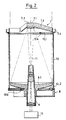
- FIG. 2 shows a telescope in the assembled state.
- the secondary mirror holder (7.1) and the secondary mirror (7.2) together with the spiders (7.3) and the circular ring (7.4) were designed as a monolithic front ring (7).
- this secondary mirror (7.2) has a convex hyperbolic shape, one of its focal points coinciding with the focal point of the main mirror (8.1).
- the second focal point of the secondary mirror (7.1) is in the vicinity of the central bore of the main mirror (8.1), from which the eyepiece (9) protrudes.
- the eyepiece (9) With the eyepiece (9) the secondary image can be observed as an inverted image. There is no real intermediate image in front of the eyepiece (9).
- the equivalent focal length of the assembled system is larger than the focal length of the main mirror (8.1), despite the short overall length.
- the monolithic front ring (7) with secondary mirror (7.1) reduces the number of parts required to build the telescope to three plus the eyepiece (9) as an assembly. This solution, which is more difficult to manufacture, reduces the risk of misalignment and avoids the problems of attaching the secondary mirror (7.2) to the secondary mirror frame (7.1).
- the spaces (10.1, 10.2) shown in this illustration between the front ring (7) and the tube (10) and the tube (10) and the base plate (8) are filled with adhesive. In order to be able to represent the intermediate spaces (10.1, 10.2) and the contact surfaces (10a, 10b), they are shown oversized in FIG. 2.
- the beam path of the telescope with the optical axis (11) is also shown in FIG. 2.
- the telescope works in the infrared at around 825 nm.
- the transition from the commonly used microwaves to infrared waves leads to several advantages: smaller design, higher transmission rate and thus transmission of more information per unit of time as well as lower power consumption during transmission (mW range in contrast to Watt range).
- Receiving and transmitting device (13) arranged according to the known prior art. This device (13) is connected to other parts of the structure, not shown here, in which the mirror telescope is installed.
Landscapes
- Physics & Mathematics (AREA)
- General Physics & Mathematics (AREA)
- Optics & Photonics (AREA)
- Astronomy & Astrophysics (AREA)
- Telescopes (AREA)
- Lenses (AREA)
Abstract
Description
- Bei der Erfindung handelt es sich um ein Spiegelteleskop mit einem Haupt- und einem Sekundärspiegel, wobei die Entfernung der beiden Spiegel durch einen Tubus festgelegt ist und der Sekundärspiegel sich an einem Frontring befindet.
- Spiegelteleskope haben aplanatische Spiegelsysteme und werden gelegentlich auch als komafreie Spiegelfernrohre bezeichnet. Sie werden vornehmlich für astrophotographische Zwecke verwendet und zeichnen sich durch eine Erfüllung der Sinusbedingung aus, wodurch ein größeres Bildfeld komafrei wird. Bei den Spiegelteleskopen dient als Objektiv ein Hohlspiegel oder ein zusammengesetztes Spiegelsystem. Zur Vermeidung der sphärischen Aberration ist der Hauptspiegel als Parabolspiegel ausgebildet. Ein wichtiger Vorteil der Spiegelteleskope ist deren Freiheit von chromatischer Aberration. Spiegelteleskope lassen sich mit weit größeren Objektivdurchmessern herstellen als Linsenfernrohre, wobei das Öffnungsverhältnis wegen des Fehlens von Restfehlern auf der optischen Achse (sekundäre Spektrum, Öffnungsfehler) wesentlich größer sein darf.
- Ein Nachteil der Spiegelteleskope ist deren große Empfindlichkeit hinsichtlich der Justierung; insbesondere, wenn die optische Qualität über mehrere Jahre ohne Nachfokussierung erhalten bleiben muß und unabhängig von Temperaturänderungen, Schüttelbelastung und Materialalterung sein soll (z.B. bei einem Einsatz in unzugängliche Baugruppen, wie es Satelliten sind).
- Der vorliegenden Erfindung liegt nun die Aufgabe zugrunde, ein Spiegelteleskop zu schaffen, welches seine optische Qualität über mehrere Jahre ohne Nachfokussierung beibehält und bei welchem man deshalb auf eine schwere und voluminöse und notwendigerweise mit einer bestimmten Ausfallwahrscheinlichkeit behafteten Nachfokussierungseinrichtung verzichten kann.
- Diese Aufgabe wird erfindungsgemäß durch ein Spiegelteleskop nach dem kennzeichnenden Teil des ersten Patentanspruches gelöst.
- Indem man sowohl die Spiegel als auch die die Distanz festlegenden Bauteile aus demselben Material fertigt, erreicht man, daß bei einer möglicherweise durch äußere Einflüsse eintretenden geometrischen Gesamtänderung (Temperatur, Alterung) alle optischen Eigenschaften (z.B. Lage des Fokus in erster Näherung) erhalten bleiben. Damit entfällt aber die Notwendigkeit einer Nachfokussierung. Um diese Gesamtänderungen als solche möglichst gering zu halten, ist der Aufbau des Spiegelteleskops aus einer möglichst geringen Bauteileanzahl vorteilhaft.
- Als Material eignet sich insbesondere Zerodur, welches ein geringes Gewicht (2,7 gr pro cm³) aufweist, sich insbesondere als Spiegelbaustoff hervorragend bewährt hat und einen geringen thermischen Ausdehnungskoeffizienten hat.
- Die minimale Anzahl der Bauteile ergibt sich aus dem verwendeten Spiegelteleskopsystem. Verwendet man ein Spiegelteleskop nach Cassegrain (welches als besonderen Vorteil eine sehr kurze Baulänge hat), so benötigt man mindestens einen Hauptspiegel mit Stützstruktur, einen Tubus, einen Frontring mit Spider und Sekundärspiegelfassung und einen Sekundärspiegel als mechanische Bauteile sowie ein Okular als Baugruppe. Eine weitere Minimierung der Bauteile erhält man, wenn man den Frontring direkt mit dem Sekundärspiegel fertigt. Diese Herstellung ist zwar fertigungstechnisch schwieriger, verringert aber die Anzahl der Bauteile und umgeht insbesondere die relativ schwierige Befestigung des Sekundärspiegels an der Sekundärspiegelfassung des Frontringes.
- Nachdem man die Teile zueinander justiert hat, werden sie vorteilhafterweise miteinander verklebt. Dieses Verkleben sollte dabei möglichst neben den mechanischen Berührungspunkten erfolgen, um die Justierung durch das Verkleben nicht zu verschlechtern.
- Das erfindungsgemäße Teleskop kann bevorzugt als optische Sende- und Empfangsantenne dienen. Der Übergang bei der Datenübertragung von Mikrowellen zu Infrarotwellen hat dabei mehrere Vorteile:
- kleinere Bauart der Antennen,
- höhere Übertragungsrate und
- geringere Leistungsaufnahme beim Sendebetrieb.
- In den nachfolgenden Figuren wird die Erfindung anhand von zwei Ausführungsbeispielen näher erläutert, wobei dem besseren Verständnis dienende Erläuterungen und Ausgestaltungsmöglichkeiten des Gedankens der Erfindung beschrieben sind.
-
- Fig. 1
- ein Spiegelteleskop mit seinen fünf Einzelteilen;
- Fig. 2
- ein zusammengebautes Spiegelteleskop mit vier Einzelteilen.
- Als in der Figur 1 dargestellte erfindungsgemäße Spiegelteleskop ist als Explosionszeichnung im Aufriß dargestellt. Die wesentlichen Gesichtspunkte bei dieser Konstruktion des Spiegelteleskops sind eine sehr hohe optische Qualität der Abbildung ohne Nachfokussierung auch nach mehreren Jahren, sowie eine kurze Baulänge und ein möglichst geringes Gewicht bei ausreichender Festigkeit insbesondere gegen Zugspannungen.
- Das Spiegelteleskop besteht aus einem Frontring (1), welcher auf einem Tubus (2) aufgesetzt wird. Der Frontring (1) hat einen umlaufenden, u-förmigen Kreisring (1a), welcher nach oben offen ist und dessen innerer Kreisringseite etwas höher gezogen ist als dessen äußere Kreisringseite. Die Seiten des Kreisringes (1a) haben alle dieselbe Wandstärke. An der nach innen gerichteten, inneren Kreisringseite sind drei Spider (1b) angebracht, deren Anlageflächen sich an der nach innen gerichteten, zur Befestigung dienenden inneren Kreisringseite aus Stabilitätsgründen etwas verbreitern. Die Wandstärke der Spider (1b) entspricht dabei der Wandstärke der Seiten des Kreisringes (1a). Die Spider (1b) haben einen Neigungswinkel α relativ zur Grundfläche des Kreisringes (1a) von ungefähr 15°. Die Breite der Spider (1b) ist fast auf ihrer gesamten Länge gleich.
- Im Zentrum des Kreisringes (1a) befindet sich eine Sekundärspiegelfassung (1c), welche durch Spider (1b) gehalten wird. Die Sekundärspiegelfassung (1c) besteht aus einem massiven runden Materialblock, dessen Durchmesser etwas kleiner ist als der Durchmesser des Sekundärspiegels (3). Damit der Sekundärspiegel (3) aber dennoch an der Sekundärspiegelfassung (1c) befestigt werden kann, sind die Spider (1b) so ausgeführt, daß sie von der Sekundärspiegelfassung (1c) zuerst waagerecht abgehen und erst dann abknicken, wenn um die Sekundärspiegelfassung (1c) ein ausreichender Raum für die Befestigung des Sekundärspiegels (3) vorhanden ist. Die Unterseite (1.1) der Sekundärspiegelfassung liegt etwas höher als die Oberkante des Kreisringes (1a) und zwar um so viel, daß die Unterseite (3.1) des Sekundärspiegels (3) genau mit der Oberkante des inneren Kreisringes (1a) abschließt, wenn der Sekundärspiegel (3) mit seiner planen Oberfläche (3.2) an der Planunterseite (1.1) der Sekundärspiegelfassung (1c) angebracht ist. Der Sekundärspiegel (3) wird dabei so ausgerichtet, daß seine optische Achse (6) genau mit der Flächennormalen der unteren Seite (1.2) des Kreisringes (1a) übereinstimmt.
- Der Frontring (1) mit angebrachtem Sekundärspiegel (3) wird dann auf den Tubus (2) aufgesetzt. Auf dem Tubus (2) befinden sich auf beiden, verdickt ausgeführten Kreisringen (2.1,2.2) jeweils drei erhabene Berührungsflächen bzw. -punkte (2.1a,2.2a). Die an dem oberen Ende (2.1) des Tubus (2) befindlichen Berührungsflächen (2.1a) dienen als mechanische Berührungspunkte (2.1a) für den Frontring (1). Nachdem alle Teile des Teleskops zueinander ausgerichtet sind, wird der Tubus (2) mit dem Frontring (1) durch Auffüllen des Zwischenraumes zwischen den drei Berührungsflächen (2.1a) mit einem geeigneten Kleber miteinander verklebt.
- Der Tubus (2) ist ein Hohlzylinder mit Kreisringflächen (2.3,2.4), auf welchen die jeweils drei erhabenen Berührungsflächen (2.1a,2.2a) angebracht sind. Die Wandstärke der seitlichen Umhüllung (2.5) entspricht dabei der Wandstärke der Seiten des Kreisringes (1a).
- Die unteren Berührungsflächen (2.2a) des Tubus (2) dienen als Berührungspunkte (2.2a) für die Basisplatte (4). Nach der Ausrichtung wird der Zwischenraum zwischen den Berührungspunkten (2.2a) mit einem geeigneten Kleber aufgefüllt und so die Basisplatte (4) relativ zum Tubus fixiert.
- Die Basisplatte (4) besteht aus einer Stützkonstruktion (4a) und einem Hauptspiegel (4b), wobei bei beiden in der Mitte eine genügend große Öffnung (4.1) für das später einzuschiebene Okular (5) vorhanden ist. In der Bohrung (4.1) befindet sich ein Absatz (4.5), um die Bewegung des Okulars (5) in das innere des Tubus (2) zu begrenzen. Die Stützstruktur (4a) unter dem Hauptspiegel (4b) besteht aus drei in einem Kreis angeordneten Hohlkörpern (4.2), wobei die Hohlkörper (4.2) zueinander den gleichen Abstand haben. Die Flächennormale der unteren Fläche (4.3) der Hohlkörper (4.2) stimmt mit der optischen Achse (6) überein. Die Hohlkörper (4.3) haben Entlüftungsbohrungen (4.4) an ihrer Oberseite.
- Das Okular (5) besitzt mehrere Linsen (5.1,5.2,5.3,5.4). Außerdem besitzt die Hülle (5.7) einen Absatz (5.6), der mit dem Absatz (4.5) der Öffnung (4.1) der Basisplatte (4) korrespondiert. Nachdem die beiden vorderen Linsen (5.1,5.2) in dem Okular (5) befestigt sind, werden die beiden hinteren Linsen (5.3,5.4) in einer separaten Fassung (5.5) in das Okular (5) eingeschoben und festgelegt. Danach wird das Okular (5) in die Öffnung (4.1) der Basisplatte (4) eingeschoben, bis sich die beiden Absätze (5.6,4.5) berühren. Dann wird das Okular (5) durch einen geeigneten Kleber in der Öffnung festgelegt.
- Alle Teile des Teleskops (1,2,3,4,5) sind aus demselben Werkstoff gefertigt. Lediglich die Linsen (5.1-5.4) des Okulars (5) müssen aus einem Werkstoff sein, welcher für die verwendete Wellenlänge transparent ist. Als Werkstoff für die Teile des Teleskops (1,2,3,4,5) eignet sich insbesondere Zerodur, welches aufgrund seines geringen spezifischen Gewichts (2,7gr/cm³) und seines minimalen Temperaturausdehnungskoeffizienten besondere Vorteile bietet und möglichst aus einer Charge stammen sollte.
- Bei der Montage des Teleskops wird zuerst der Sekundärspiegel (3) an der Sekundärspiegelfassung (1c) des Frontringes (1) ausgerichtet und befestigt. Danach erfolgt die Ausrichtung des Sekundärspiegels (3) relativ zum Hauptspiegel (4b) durch eine Polierjustierung mit anschließender Verklebung. Dabei wird an den jeweils drei erhabenen Berührungsflächen (2.1a,2.2a) an den Enden (2.1,2.2) des Tubus (2) durch Läppen eine Justierung des Frontringes (1) mit angebrachtem Sekundärspiegel (3) zur Basisplatte (4) mit dem Hauptspiegel (4b) im 1/10µm-Bereich vorgenommen. Dies ermöglicht es, die zulässige Entfernungstoleranz zwischen dem Hauptspiegel (4b) und dem Sekundärspiegel (3) durch z.B. thermische Einflüsse oder nach einem Schock kleiner als 2µm zu halten. Nach erfolgter Justierung wird der Bereich zwischen den erhabenen Berührungsflächen (2.1a,2.2a) mit einem geeigneten Kleber aufgefüllt. Die Eignung eines Klebers für diese Anwendung besteht in einem, den Teilen (1,2,3,4,5) des Teleskops angepaßten thermischen Ausdehnungskoeffizienten und in einer hohen Alterungsbeständigkeit des Klebers. Zuletzt wird das Okular (5) in die Öffnung (4.1) der Basisplatte (4) eingeschoben. Dabei ist darauf zu achten, daß parallele Eingangsstrahlenbündel des Teleskops das Okular (5) als auch parallele Ausgangsstrahlenbündel verlassen.
- Das in Fig. 1 dargestellte Teleskop hat einen Hauptspiegeldurchmesser von ungefähr 250 mm, einen Gesamtdurchmesser von ungefähr 310 mm und im zusammengebauten Zustand eine Gesamtlänge von ungefähr 450 mm bei einem Gewicht von kleiner als 8,5 kg. Es eignet sich insbesondere als Antenne/Sender für eine optische Telekommunikation im Weltraum. Daraus resultieren auch die sehr hohen Forderungen an die Justierung der Teile (1,2,3,4,5) des Teleskops, welche über mindestens 10 Jahre ohne Nachfokussierung erhalten bleiben muß. Das bei dem Teleskop verwendete Cassegrain-System mit Okular (5) erlaubt insbesondere die sehr kurze Bauweise, welche ihrerseits zu einer beträchtlichen Gewichtseinsparung führt. Die Öffnung des Hauptspiegels beträgt 1:1,5.
- Hinter dem Okular (5) ist eine optische Empfangs- und Sendereinrichtung (12) nach dem bekannten Stand der Technik angeordnet, welche mit Teilen des Systems in Verbindung steht, in welches das Teleskop eingebaut ist.
- In Fig. 2 ist nun ein Teleskop im zusammengebauten Zustand dargestellt. Dabei wurde im Gegensatz zu Fig. 1 allerdings die Sekundärspiegelfassung (7.1) und der Sekundärspiegel (7.2) zusammen mit den Spidern (7.3) und dem Kreisring (7.4) als monolithischer Frontring (7) ausgeführt. Wie in Fig. 1 hat dieser Sekundärspiegel (7.2) eine konvexhyperbolische Form, wobei einer seiner Brennpunkte mit dem Brennpunkt des Hauptspiegels (8.1) zusammenfällt. Der zweite Brennpunkt des Sekundärspiegels (7.1) befindet sich in der Nähe der zentralen Bohrung des Hauptspiegels (8.1), aus welchem das Okular (9) herausragt. Mit dem Okular (9) kann das sekundäre Bild als umgekehrtes Bild beobachtet werden. Ein reelles Zwischenbild kommt vor dem Okular (9) nicht zustande. Bei dem Teleskop ist die Äquivalenzbrennweite des zusammengesetzten Systems größer als die Brennweite des Hauptspiegels (8.1), trotz der kurzen Baulänge.
- Durch den monolithischen Frontring (7) mit Sekundärspiegel (7.1) reduziert sich die Zahl der zum Bau des Teleskops benötigten Teile auf drei zuzüglich des Okulars (9) als Baugruppe. Diese fertigungstechnisch schwierigere Lösung führt zu einer Verringerung der Gefahr einer Dejustage und umgeht die Probleme der Befestigung des Sekundärspiegels (7.2) an der Sekundärspiegelfassung (7.1). Die in dieser Darstellung gezeigten Zwischenräume (10.1,10.2) zwischen dem Frontring (7) und dem Tubus (10) sowie dem Tubus (10) und der Basisplatte (8) sind mit Kleber aufgefüllt. Um die Zwischenräume (10.1,10.2) und die Berührungsflächen (10a,10b) darstellen zu können, sind sie in Fig. 2 überdimensional dargestellt. Außerdem ist in Fig. 2 der Strahlengang des Teleskops mit der optischen Achse (11) dargestellt.
- Das Teleskop arbeitet im Infraroten bei ungefähr 825 nm. Der Übergang von den üblicherweise verwendeten Mikrowellen zu Infrarotwellen führt zu mehreren Vorteilen: kleinere Bauart, höhere Übertragungsrate und damit Übertragung von mehr Information pro Zeiteinheit sowie eine geringere Leistungsaufnahme beim Sendebetrieb (mW-Bereich im Gegensatz zu Watt-Bereich). Damit eignet sich das Teleskop hervorragend für Übertragungen im außeratmosphärischen Bereich. Zur Durchführung von Sendungen und dem Empfang von Infrarotsignalen ist hinter dem Okular (9) eine optische Empfangs- und Sendeeinrichtung (13) nach dem bekannten Stand der Technik angeordnet. Diese Einrichtung (13) besteht mit weiteren, hier nicht eingezeichneten Teilen des Baukörpers in Verbindung, in welches das Spiegelteleskop eingebaut ist.
Claims (9)
- Spiegelteleskop mit einem Haupt- und einem Sekundärspiegel, wobei die Entfernung der beiden Spiegel durch einen Tubus festgelegt ist und der Sekundärspiegel sich an einem Frontring befindet, dadurch gekennzeichnet, daß sowohl der Haupt- (4b;8.1) als auch der Sekundärspiegel (3;7.2) sowie alle die Distanz festlegenden und beeinflußenden Bauteile (1,2;10) aus demselben Material hergestellt sind.
- Spiegelteleskop nach Anspruch 1, dadurch gekennzeichnet, daß das Material Zerodur ist.
- Spiegelteleskop nach Anspruch 1 oder 2, dadurch gekennzeichnet, daß das Spiegelteleskop aus einem Frontring (1;7) mit Sekundärspiegelfassung (1c;7.2), einen Sekundärspiegel (3;7.1), einem Tubus (2;10) und einer Basisplatte (4;8) mit Hauptspiegel (4b;8.1) als mechanische Bauteile sowie einem Okular (5;9) als Baugruppe besteht.
- Spiegelteleskop nach Anspruch 3, dadurch gekennzeichnet, daß der Frontring (7) mit der Sekundärspiegelfassung (7.2) und dem Sekundärspiegel (7.1) ein einziges monolithisches, mechanisches Bauteil ist.
- Spiegelteleskop nach einem der Ansprüche 1 - 4, dadurch gekennzeichnet, daß das Spiegelteleskop als ein Cassegrain-System ausgebildet ist.
- Spiegelteleskop nach einem der Ansprüche 1 - 5, dadurch gekennzeichnet, daß sowohl die mechanischen Teile (1,2,3,4;7,8,10) als auch die Baugruppe (5;9) zur Fixierung ihrer Lage zueinander miteinander verklebt sind.
- Spiegelteleskop nach einem der Ansprüche 1 - 6, dadurch gekennzeichnet, daß jeweils drei mechanische Berührungspunkte (2.1a,2.2a;10a,10b) an den Enden des Tubus (2;10) vorhanden sind, mit welchen eine Festlegung der Entfernung zwischen dem Sekundärspiegel (3;7.1) und dem Hauptspiegel (4b;8.1) und eine Ausrichtung der beiden Spiegel (3,4b;7.1,8.1) zu einer gemeinsamen optischen Achse (6;11) erfolgt.
- Spiegelteleskop nach Anspruch 7, dadurch gekennzeichnet, daß die Flächen auf dem Kreisumfang des Tubus (2;10) neben den mechanischen Berührungspunkten (2.1a,2.2a;10a,10b) als Klebefläche verwendet sind.
- Spiegelteleskop nach einem der Ansprüche 1 - 8, dadurch gekennzeichnet, daß hinter dem Okular (5;9) des Spiegelteleskops eine optische, infrarotempfindliche Empfangs- und Sendeeinrichtung (12;13) angeordnet ist.
Applications Claiming Priority (2)
| Application Number | Priority Date | Filing Date | Title |
|---|---|---|---|
| DE3940924 | 1989-12-12 | ||
| DE3940924A DE3940924A1 (de) | 1989-12-12 | 1989-12-12 | Spiegelteleskop |
Publications (3)
| Publication Number | Publication Date |
|---|---|
| EP0432618A2 true EP0432618A2 (de) | 1991-06-19 |
| EP0432618A3 EP0432618A3 (en) | 1991-09-18 |
| EP0432618B1 EP0432618B1 (de) | 1995-03-08 |
Family
ID=6395264
Family Applications (1)
| Application Number | Title | Priority Date | Filing Date |
|---|---|---|---|
| EP90123267A Expired - Lifetime EP0432618B1 (de) | 1989-12-12 | 1990-12-05 | Spiegelteleskop |
Country Status (4)
| Country | Link |
|---|---|
| US (1) | US5138484A (de) |
| EP (1) | EP0432618B1 (de) |
| CA (1) | CA2032001C (de) |
| DE (2) | DE3940924A1 (de) |
Cited By (4)
| Publication number | Priority date | Publication date | Assignee | Title |
|---|---|---|---|---|
| FR2736165A1 (fr) * | 1995-06-30 | 1997-01-03 | Vernois Goulven Jean Alain | Telescope satellise |
| DE19962831A1 (de) * | 1999-12-23 | 2001-07-12 | Dlr Ev | Teleskop |
| RU2321872C2 (ru) * | 2005-11-08 | 2008-04-10 | Федеральное государственное унитарное предприятие "Производственное объединение "Новосибирский приборостроительный завод" (ФГУП "ПО "НПЗ") | Узел крепления и юстировки астрономического зеркала в трубе телескопа |
| RU2536322C1 (ru) * | 2013-04-29 | 2014-12-20 | Открытое акционерное общество "Лыткаринский завод оптического стекла" | Способ позиционирования и приклейки вспомогательных элементов крупногабаритных оптических деталей |
Families Citing this family (18)
| Publication number | Priority date | Publication date | Assignee | Title |
|---|---|---|---|---|
| CN1099604C (zh) * | 1999-06-18 | 2003-01-22 | 中国科学院上海技术物理研究所 | 空间用大口径光学主镜支承装置 |
| US6795260B2 (en) | 1999-12-09 | 2004-09-21 | Contraves Space Ag | Optical unit and its use |
| CH694744A5 (de) * | 1999-12-09 | 2005-06-30 | Contraves Space Ag | Optische Einheit und deren Verwendung. |
| RU2201608C2 (ru) * | 2001-04-18 | 2003-03-27 | Государственное унитарное предприятие "Производственное объединение "Новосибирский приборостроительный завод" | Способ крепления астрономического зеркала в трубе телескопа |
| FR2857106B1 (fr) * | 2003-07-04 | 2005-09-30 | Cit Alcatel | Telescope a tres haute resolution |
| US7486438B2 (en) * | 2005-04-28 | 2009-02-03 | Institut National D'optique | High-resolution optical imaging systems |
| FR2930352B1 (fr) | 2008-04-21 | 2010-09-17 | Commissariat Energie Atomique | Membrane perfectionnee notamment pour dispositif optique a membrane deformable |
| US10018851B2 (en) | 2014-08-14 | 2018-07-10 | Yakov Soskind | Optical field transformation methods and systems |
| US10732378B2 (en) * | 2017-01-25 | 2020-08-04 | Flir Systems, Inc. | Mounting optical elements in optical systems |
| RU2672777C2 (ru) * | 2017-02-02 | 2018-11-19 | Публичное акционерное общество "Ростовский оптико-механический завод" | Зеркально-линзовый объектив |
| FR3070502B1 (fr) * | 2017-08-22 | 2020-06-26 | Safran Electronics & Defense | Telescope a montage simplifie et procede de reglage d'un tel telescope |
| FR3072784B1 (fr) * | 2017-10-19 | 2019-11-15 | Thales | Telescope de type korsh ameliore |
| JP7102802B2 (ja) * | 2018-03-14 | 2022-07-20 | 日本電気株式会社 | 光学系支持機構 |
| US10534165B1 (en) * | 2018-09-07 | 2020-01-14 | Bae Systems Information And Electronic Systems Integration Inc. | Athermal cassegrain telescope |
| RU189105U1 (ru) * | 2018-11-07 | 2019-05-13 | Андрей Иванович Клем | Датчик углового рассогласования |
| US10495839B1 (en) | 2018-11-29 | 2019-12-03 | Bae Systems Information And Electronic Systems Integration Inc. | Space lasercom optical bench |
| DE112019005629T5 (de) * | 2018-12-13 | 2021-07-29 | Mitsubishi Electric Corporation | Optische Vorrichtung |
| CN111781719B (zh) * | 2020-07-21 | 2021-12-07 | 中国科学院长春光学精密机械与物理研究所 | 一种大口径大视场望远镜系统内置测量装置及其测量方法 |
Family Cites Families (9)
| Publication number | Priority date | Publication date | Assignee | Title |
|---|---|---|---|---|
| FR2449380A1 (fr) * | 1979-02-15 | 1980-09-12 | Onera (Off Nat Aerospatiale) | Camera infrarouge a miroir vibrant |
| BE887757A (fr) * | 1980-03-05 | 1981-07-01 | Barr & Stroud Ltd | Systeme pour objectifs de lunettes |
| DE3214269A1 (de) * | 1982-04-17 | 1983-10-20 | Zeiss Carl Fa | Gekuehlte feldoptik fuer infrarotteleskope |
| US4624538A (en) * | 1985-05-28 | 1986-11-25 | The Perkin-Elmer Corporation | Coma-compensation telescope |
| US5016265A (en) * | 1985-08-15 | 1991-05-14 | The United States Of America As Represented By The Administrator Of The National Aeronautics And Space Administration | Variable magnification variable dispersion glancing incidence imaging x-ray spectroscopic telescope |
| US4649274A (en) * | 1985-08-22 | 1987-03-10 | The United States Of America As Represented By The Secretary Of The Army | Temperature stable boresight module |
| GB8605031D0 (en) * | 1986-02-28 | 1986-04-09 | Gec Avionics | Fixed prealignment of laser optics |
| DE3707642C1 (de) * | 1987-03-06 | 1988-03-10 | Herman Huegenell | Spiegelteleskop |
| EP0315030A1 (de) * | 1987-11-05 | 1989-05-10 | Siemens Aktiengesellschaft | Laserröhre |
-
1989
- 1989-12-12 DE DE3940924A patent/DE3940924A1/de not_active Withdrawn
-
1990
- 1990-12-05 DE DE59008635T patent/DE59008635D1/de not_active Expired - Fee Related
- 1990-12-05 EP EP90123267A patent/EP0432618B1/de not_active Expired - Lifetime
- 1990-12-10 US US07/624,598 patent/US5138484A/en not_active Expired - Lifetime
- 1990-12-11 CA CA002032001A patent/CA2032001C/en not_active Expired - Fee Related
Cited By (5)
| Publication number | Priority date | Publication date | Assignee | Title |
|---|---|---|---|---|
| FR2736165A1 (fr) * | 1995-06-30 | 1997-01-03 | Vernois Goulven Jean Alain | Telescope satellise |
| DE19962831A1 (de) * | 1999-12-23 | 2001-07-12 | Dlr Ev | Teleskop |
| DE19962831C2 (de) * | 1999-12-23 | 2002-10-10 | Deutsch Zentr Luft & Raumfahrt | Teleskop |
| RU2321872C2 (ru) * | 2005-11-08 | 2008-04-10 | Федеральное государственное унитарное предприятие "Производственное объединение "Новосибирский приборостроительный завод" (ФГУП "ПО "НПЗ") | Узел крепления и юстировки астрономического зеркала в трубе телескопа |
| RU2536322C1 (ru) * | 2013-04-29 | 2014-12-20 | Открытое акционерное общество "Лыткаринский завод оптического стекла" | Способ позиционирования и приклейки вспомогательных элементов крупногабаритных оптических деталей |
Also Published As
| Publication number | Publication date |
|---|---|
| DE59008635D1 (de) | 1995-04-13 |
| EP0432618A3 (en) | 1991-09-18 |
| EP0432618B1 (de) | 1995-03-08 |
| US5138484A (en) | 1992-08-11 |
| CA2032001C (en) | 2001-03-20 |
| CA2032001A1 (en) | 1991-06-13 |
| DE3940924A1 (de) | 1991-06-13 |
Similar Documents
| Publication | Publication Date | Title |
|---|---|---|
| EP0432618B1 (de) | Spiegelteleskop | |
| DE19502431B4 (de) | Optische Schaltvorrichtung | |
| EP1297372B1 (de) | Vorrichtung zur übertragung optischer signale | |
| DE3128190C2 (de) | ||
| WO2020069787A1 (de) | Aktuatoreinrichtung zur ausrichtung eines elements, projektionsbelichtungsanlage für die halbleiterlithografie und verfahren zur ausrichtung eines elements | |
| EP1574808B1 (de) | Zielfernrohr | |
| DE102016100478B4 (de) | Kamera für einen Raumflugkörper | |
| DE3232509A1 (de) | Fassung fuer ein objektiv mit veraenderlicher brennweite | |
| EP0800660A2 (de) | Zielfernrohr mit variabler vergrösserung | |
| DE3500123C2 (de) | ||
| DE3330901C2 (de) | ||
| DD144985A5 (de) | Aufnahmeroehre und verfahren zu deren herstellung | |
| DE102016116410A1 (de) | Optisches system zur einkopplung von laserlicht in eine lichtleitfaser, insbesondere eine einmoden-faser und ein verfahren zur erhöhung einer einstellgenauigkeit eines fokus eines lichtstrahls | |
| DE19724180C2 (de) | Monolithischer optischer Lagesensor | |
| EP0382737B1 (de) | Optisches system, das aus wenigstens zwei teilsystemen besteht | |
| EP1651981B1 (de) | Vorrichtung zum justieren eines optischen spiegels | |
| DD242105A1 (de) | Beleuchtungseinrichtung fuer mikroskope und projektoren | |
| DE3200938A1 (de) | Faseroptische mehrpunktleuchte mit variabler brennweite | |
| DD250784A1 (de) | Optische anordnung mit radialer und axialer temperaturkompensation | |
| DE3876571T2 (de) | Kardanische aufhaengung. | |
| DE102017113402B4 (de) | Fernoptisches Gerät, Mehrachsen-Justiervorrichtung und Verfahren zum Justieren eines fernoptischen Geräts | |
| EP1273962B1 (de) | Beleuchtungsvorrichtung für eine Bilderzeugungsvorrichtung | |
| DE10128827A1 (de) | Justierverfahren, insbesondere Laser-Justierverfahren und hierfür geeigneter Aktor | |
| DE19605033A1 (de) | Aplanatisches, anastigmatisches Spiegelsystem mit 2 Spiegeln, 3 Flächen und 4 Reflexionen | |
| WO2025021886A1 (de) | Einrichtung zur bewegung einer optik und laserbearbeitungsvorrichtung |
Legal Events
| Date | Code | Title | Description |
|---|---|---|---|
| PUAI | Public reference made under article 153(3) epc to a published international application that has entered the european phase |
Free format text: ORIGINAL CODE: 0009012 |
|
| AK | Designated contracting states |
Kind code of ref document: A2 Designated state(s): DE FR GB IT NL |
|
| PUAL | Search report despatched |
Free format text: ORIGINAL CODE: 0009013 |
|
| AK | Designated contracting states |
Kind code of ref document: A3 Designated state(s): DE FR GB IT NL |
|
| 17P | Request for examination filed |
Effective date: 19920226 |
|
| 17Q | First examination report despatched |
Effective date: 19940321 |
|
| ITF | It: translation for a ep patent filed | ||
| GRAA | (expected) grant |
Free format text: ORIGINAL CODE: 0009210 |
|
| RAP1 | Party data changed (applicant data changed or rights of an application transferred) |
Owner name: CARL ZEISS-STIFTUNG HANDELND ALS CARL ZEISS Owner name: CARL ZEISS |
|
| AK | Designated contracting states |
Kind code of ref document: B1 Designated state(s): DE FR GB IT NL |
|
| REF | Corresponds to: |
Ref document number: 59008635 Country of ref document: DE Date of ref document: 19950413 |
|
| GBT | Gb: translation of ep patent filed (gb section 77(6)(a)/1977) |
Effective date: 19950518 |
|
| ET | Fr: translation filed | ||
| PLBE | No opposition filed within time limit |
Free format text: ORIGINAL CODE: 0009261 |
|
| STAA | Information on the status of an ep patent application or granted ep patent |
Free format text: STATUS: NO OPPOSITION FILED WITHIN TIME LIMIT |
|
| 26N | No opposition filed | ||
| REG | Reference to a national code |
Ref country code: GB Ref legal event code: IF02 |
|
| REG | Reference to a national code |
Ref country code: GB Ref legal event code: 732E |
|
| NLS | Nl: assignments of ep-patents |
Owner name: CARL ZEISS SMT AG |
|
| REG | Reference to a national code |
Ref country code: FR Ref legal event code: TP |
|
| PGFP | Annual fee paid to national office [announced via postgrant information from national office to epo] |
Ref country code: NL Payment date: 20071213 Year of fee payment: 18 |
|
| PGFP | Annual fee paid to national office [announced via postgrant information from national office to epo] |
Ref country code: IT Payment date: 20071222 Year of fee payment: 18 |
|
| PGFP | Annual fee paid to national office [announced via postgrant information from national office to epo] |
Ref country code: GB Payment date: 20071218 Year of fee payment: 18 |
|
| PGFP | Annual fee paid to national office [announced via postgrant information from national office to epo] |
Ref country code: DE Payment date: 20071221 Year of fee payment: 18 |
|
| PGFP | Annual fee paid to national office [announced via postgrant information from national office to epo] |
Ref country code: FR Payment date: 20071217 Year of fee payment: 18 |
|
| GBPC | Gb: european patent ceased through non-payment of renewal fee |
Effective date: 20081205 |
|
| NLV4 | Nl: lapsed or anulled due to non-payment of the annual fee |
Effective date: 20090701 |
|
| REG | Reference to a national code |
Ref country code: FR Ref legal event code: ST Effective date: 20090831 |
|
| PG25 | Lapsed in a contracting state [announced via postgrant information from national office to epo] |
Ref country code: DE Free format text: LAPSE BECAUSE OF NON-PAYMENT OF DUE FEES Effective date: 20090701 |
|
| PG25 | Lapsed in a contracting state [announced via postgrant information from national office to epo] |
Ref country code: NL Free format text: LAPSE BECAUSE OF NON-PAYMENT OF DUE FEES Effective date: 20090701 Ref country code: GB Free format text: LAPSE BECAUSE OF NON-PAYMENT OF DUE FEES Effective date: 20081205 |
|
| PG25 | Lapsed in a contracting state [announced via postgrant information from national office to epo] |
Ref country code: FR Free format text: LAPSE BECAUSE OF NON-PAYMENT OF DUE FEES Effective date: 20081231 |
|
| PG25 | Lapsed in a contracting state [announced via postgrant information from national office to epo] |
Ref country code: IT Free format text: LAPSE BECAUSE OF NON-PAYMENT OF DUE FEES Effective date: 20081205 |