EP0432143B1 - Verfahren und Verwendung einer Anordnung zur Prüfung mindestens eines Hohlkörpers auf sein Volumenverhalten - Google Patents
Verfahren und Verwendung einer Anordnung zur Prüfung mindestens eines Hohlkörpers auf sein Volumenverhalten Download PDFInfo
- Publication number
- EP0432143B1 EP0432143B1 EP91104023A EP91104023A EP0432143B1 EP 0432143 B1 EP0432143 B1 EP 0432143B1 EP 91104023 A EP91104023 A EP 91104023A EP 91104023 A EP91104023 A EP 91104023A EP 0432143 B1 EP0432143 B1 EP 0432143B1
- Authority
- EP
- European Patent Office
- Prior art keywords
- pressure
- volume
- hollow body
- test chamber
- predetermined
- Prior art date
- Legal status (The legal status is an assumption and is not a legal conclusion. Google has not performed a legal analysis and makes no representation as to the accuracy of the status listed.)
- Expired - Lifetime
Links
- 238000012360 testing method Methods 0.000 title claims description 68
- 238000000034 method Methods 0.000 title claims description 20
- 230000001419 dependent effect Effects 0.000 claims description 6
- 239000002131 composite material Substances 0.000 abstract 1
- 238000011156 evaluation Methods 0.000 description 8
- 238000009530 blood pressure measurement Methods 0.000 description 6
- 238000010586 diagram Methods 0.000 description 2
- 238000005259 measurement Methods 0.000 description 2
- 206010041953 Staring Diseases 0.000 description 1
- 230000000052 comparative effect Effects 0.000 description 1
- 230000000694 effects Effects 0.000 description 1
- 230000005489 elastic deformation Effects 0.000 description 1
- 238000003780 insertion Methods 0.000 description 1
- 230000037431 insertion Effects 0.000 description 1
- 238000004519 manufacturing process Methods 0.000 description 1
- 230000001105 regulatory effect Effects 0.000 description 1
- 238000007789 sealing Methods 0.000 description 1
- 238000003860 storage Methods 0.000 description 1
- 230000002123 temporal effect Effects 0.000 description 1
- 238000010998 test method Methods 0.000 description 1
- 230000001960 triggered effect Effects 0.000 description 1
- 238000003466 welding Methods 0.000 description 1
Images

Classifications
-
- B—PERFORMING OPERATIONS; TRANSPORTING
- B07—SEPARATING SOLIDS FROM SOLIDS; SORTING
- B07C—POSTAL SORTING; SORTING INDIVIDUAL ARTICLES, OR BULK MATERIAL FIT TO BE SORTED PIECE-MEAL, e.g. BY PICKING
- B07C5/00—Sorting according to a characteristic or feature of the articles or material being sorted, e.g. by control effected by devices which detect or measure such characteristic or feature; Sorting by manually actuated devices, e.g. switches
- B07C5/34—Sorting according to other particular properties
- B07C5/3404—Sorting according to other particular properties according to properties of containers or receptacles, e.g. rigidity, leaks, fill-level
- B07C5/3408—Sorting according to other particular properties according to properties of containers or receptacles, e.g. rigidity, leaks, fill-level for bottles, jars or other glassware
-
- G—PHYSICS
- G01—MEASURING; TESTING
- G01F—MEASURING VOLUME, VOLUME FLOW, MASS FLOW OR LIQUID LEVEL; METERING BY VOLUME
- G01F17/00—Methods or apparatus for determining the capacity of containers or cavities, or the volume of solid bodies
-
- G—PHYSICS
- G01—MEASURING; TESTING
- G01M—TESTING STATIC OR DYNAMIC BALANCE OF MACHINES OR STRUCTURES; TESTING OF STRUCTURES OR APPARATUS, NOT OTHERWISE PROVIDED FOR
- G01M3/00—Investigating fluid-tightness of structures
- G01M3/02—Investigating fluid-tightness of structures by using fluid or vacuum
- G01M3/26—Investigating fluid-tightness of structures by using fluid or vacuum by measuring rate of loss or gain of fluid, e.g. by pressure-responsive devices, by flow detectors
- G01M3/32—Investigating fluid-tightness of structures by using fluid or vacuum by measuring rate of loss or gain of fluid, e.g. by pressure-responsive devices, by flow detectors for containers, e.g. radiators
- G01M3/3236—Investigating fluid-tightness of structures by using fluid or vacuum by measuring rate of loss or gain of fluid, e.g. by pressure-responsive devices, by flow detectors for containers, e.g. radiators by monitoring the interior space of the containers
- G01M3/3263—Investigating fluid-tightness of structures by using fluid or vacuum by measuring rate of loss or gain of fluid, e.g. by pressure-responsive devices, by flow detectors for containers, e.g. radiators by monitoring the interior space of the containers using a differential pressure detector
-
- G—PHYSICS
- G01—MEASURING; TESTING
- G01M—TESTING STATIC OR DYNAMIC BALANCE OF MACHINES OR STRUCTURES; TESTING OF STRUCTURES OR APPARATUS, NOT OTHERWISE PROVIDED FOR
- G01M3/00—Investigating fluid-tightness of structures
- G01M3/02—Investigating fluid-tightness of structures by using fluid or vacuum
- G01M3/26—Investigating fluid-tightness of structures by using fluid or vacuum by measuring rate of loss or gain of fluid, e.g. by pressure-responsive devices, by flow detectors
- G01M3/32—Investigating fluid-tightness of structures by using fluid or vacuum by measuring rate of loss or gain of fluid, e.g. by pressure-responsive devices, by flow detectors for containers, e.g. radiators
- G01M3/3281—Investigating fluid-tightness of structures by using fluid or vacuum by measuring rate of loss or gain of fluid, e.g. by pressure-responsive devices, by flow detectors for containers, e.g. radiators removably mounted in a test cell
- G01M3/329—Investigating fluid-tightness of structures by using fluid or vacuum by measuring rate of loss or gain of fluid, e.g. by pressure-responsive devices, by flow detectors for containers, e.g. radiators removably mounted in a test cell for verifying the internal pressure of closed containers
Definitions
- the present invention relates to a method and a use of an arrangement for detecting the volume behavior of a hollow body due to a pressure load on its walls.
- the present invention is based on the object of creating a test method for hollow bodies of this type and of using an arrangement with which hollow bodies of this type are to be tested in a simple manner and with great reliability.
- the procedure according to claim 2 takes advantage of the fact that if such a hollow body is introduced into a test chamber and a positive or negative differential pressure of a test gas, preferably air, is applied in the test chamber with regard to the hollow body pressure, on the one hand there is a pressure equalization between the test chamber pressure and the internal pressure of the hollow body depending on the density or leakage on the hollow body whose time behavior is a measure of the size of any leakage that may be present.
- a test gas preferably air
- an increase or decrease in volume of the hollow body has an effect - an increase in the differential pressure directed outwards from the hollow body interior, a decrease in the differential pressure directed towards the interior of the hollow body - and is a measure of the elasticity of the hollow body wall.
- a chamber with a predetermined volume is considered to be one charged predetermined pressure and then connected this chamber to the test chamber.
- the pressure in the test chamber results on the one hand from the charge pressure of the chamber and the volume ratio of the two chambers with the hollow body.
- the test chamber can be preloaded with a positive or negative pressure with regard to atmospheric pressure.
- test chamber is first connected to a reference pressure system and then the reference pressure system is separated from the chamber and uses its pressure as a reference pressure for the subsequent evaluation of the chamber pressure.
- the reference pressure system is initially connected to the chamber, the same pressure is set in it as in the test chamber. If the reference pressure system is then separated from the chamber, the pressure value prevailing in the test chamber remains stored in the reference pressure system and serves as a reference pressure for a differential pressure measurement in the subsequent evaluation.
- a check is carried out to determine whether the ACTUAL chamber pressure corresponds to a previously determined TARGET chamber pressure. If the ACTUAL test chamber pressure is compared at two or more points in time or even in its continuous time course with TARGET pressure values at two or more points in time or with a TARGET pressure time curve, this results in an increase in the evaluation resolution, e.g. by integrating the comparison result or the TARGET-ACTUAL difference.
- Predefined pressure values are preferred in the following or SHOULD pressure curves are stored and compared in the above-mentioned test as a comparative value with the then registered actual values, in order to conclude, for example, that hollow parts are rejected due to parts of the wall that are too stiff or too elastic.
- EP-A-0060548 a method and a device for density testing of electrical components is known.
- the component to be tested is placed in a test chamber, which is pressurized.
- the pressure in the test chamber is pressurized through a chamber with a given volume, which is charged to a predetermined pressure value, and the behavior of the pressure in the differential volume between the test chamber volume and the component volume is used to infer the sealing behavior of the component.
- this arrangement which is known per se, is excellently suited for testing the volume behavior of hollow bodies on which the present invention is based.
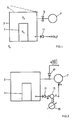
- a hollow body 1 should then be checked as its volume changes due to pressure, due to the elastic deformation of its walls.
- the hollow body 1 is introduced into a test chamber 3, for example through an insertion opening which can be tightly closed by means of a cover 5.
- the test chamber 3 is pressurized by connecting a pressure medium source 7 of the test chamber 3.
- a gas preferably air, is used as the pressure medium.
- a positive or negative differential pressure is generated in the test chamber 3 with reference to the internal pressure p il within the hollow body 1.
- the pressure inside the test chamber 3 is designated in Fig. 1 with p3. Then the pressure system, consisting of the test chamber 3 and the hollow body 1 to be tested, is separated from the pressure medium source 7, as with a shut-off valve 9, and left to its own devices. If the hollow body 1 is tight with respect to the gas used and its walls are so rigid that the forces resulting from the pressure difference between p3 and p i1 on the walls do not cause any noticeable deformations, then with a pressure sensor as shown schematically in FIG. 1 at 11 , for example as a mechanical / electrical converter, such as a piezzo pressure sensor, an output signal s (p3), as shown qualitatively in Fig. 2a, registered.
- a pressure sensor as shown schematically in FIG. 1 at 11 , for example as a mechanical / electrical converter, such as a piezzo pressure sensor, an output signal s (p3), as shown qualitatively in Fig. 2a, registered.
- the pressure in the test chamber 3 corresponding to the signal s (p3) and the internal pressure p i1 in the hollow body 1 is plotted qualitatively over time t. Up to the point in time t 1 until where the hollow body 1 has been inserted into the test chamber 3 and the latter has been sealed with the cover 5, p 3 and p il are equal to the ambient pressure P u . At the time t 1 begins to put the test chamber 3 under pressure with the source 7, the pressure in the test chamber 3 increases. In the case of rigid and dense hollow body walls mentioned above, the internal pressure p il remains unaffected by the pressure change in the test chamber 3. At the time t2, the source 7 is separated from the test chamber 3, in the present case the test chamber pressure p3 (a) remains at least almost constant and likewise the internal pressure p i1 (a) in the hollow body 1.
- both pressures aim for a different, constant limit value asymptotically after a shorter or longer time.
- FIG. 2b the situation in the case of existing, differently sized leaks on the hollow body 1 is shown in an analogous representation to FIG. 2a.
- the internal pressure of the hollow body 1 and the pressure between the test chamber 3 and the hollow body 1 balance out relatively slowly in accordance with the qualitative profiles p (c), with larger leakages increasingly faster, as shown, for example, with the profiles p (d).
- the output side of the sensor 11 is compared by comparing the actual curve with such a target curve assesses how far a tested hollow body is tight or not or whether it should be rejected or not.
- the pressure p3 is measured, for example with reference to the ambient atmosphere with pressure p u , advantageously and as will be described below , a differential pressure measurement of the pressure p3 is carried out with respect to a predetermined reference pressure.
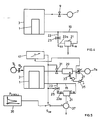
- a further variant is shown in FIG. 3, in which the pressure in the test chamber 3 is constantly regulated and the pressure medium quantity or gas quantity per gas unit supplied or discharged for this purpose or integrated over a predetermined period of time is recorded as a measured variable .
- the latter is pressurized by means of a medium source 7, such as with air or again evacuated, and the internal pressure of the test chamber 3 is measured as a controlled variable W with a pressure sensor 11 .
- the controlled variable W is compared on a differential unit 13 with a reference pressure X or a signal corresponding to the reference pressure, and the resulting control difference ⁇ is applied to a control input S7 of the source 7.
- the pressure in the test chamber 3 is set to the SET value X set on a specification unit 15.
- the medium volume per unit of time to be supplied by the source 7 as an actuator of the test chamber 3 is recorded on a flow sensor 17 as a signal s ( ⁇ V ⁇ t ), which is integrated for further evaluation, for example over a predetermined period of time.
- the test chamber 3 is connected via a line 19 to the one input E 1 of a differential pressure sensor 21, such as a piezoelectric sensor. Via a second line 23, with a shut-off valve 25, the test chamber 3 is further connected to the second input E23 of the differential pressure sensor 21.
- the shut-off valve 25 is closed, so that in line piece 23 a , as a reference pressure system, between shut-off valve 25 and inlet E23, the pressure prevailing in the test chamber 3 then remains built up.
- This pressure in the connection 23 a acts as a reference pressure on the differential pressure sensor 21 and since the line 19 remains open for t> t 2 in the subsequent measuring phase, a differential pressure measurement at the differential pressure sensor 21 results with reference to the test chamber pressure at the time t R.
- the time t R is set on a case-specific basis for optimal measurement resolution, as represented by t R ′ , t R ⁇ and the resulting reference pressures p R , p R ′ , p R ⁇ .
- a test gas source such as a pump 7 a
- a reference volume in a reference chamber 29 via a shut-off valve 27.
- the latter is connected to the test chamber 3 via a further shut-off valve 31.
- the reference chamber 29 is filled with test gas and the pressure is measured therein by means of a pressure sensor 33. If the pressure measured by the sensor 33 reaches a reference pressure set at a reference signal source 35, the valve 27 is blocked.
- valve 31 is then opened, whereby the chambers 3 and 29 form a communicating system and a test gas equalization is established in accordance with the volumes in chamber 29 and in chamber 3.
- a test gas equalization is established in accordance with the volumes in chamber 29 and in chamber 3.
- the course of the differential pressure is measured with the differential pressure sensor 21 or, at a predetermined measuring time t m according to FIG. 2b, differences between a TARGET Pressure difference and an actual pressure difference registered.
- the output of the differential pressure sensor 21 is fed, for example, to a differential unit 37 which, at a second input, has a storage and output device, shown schematically at 39, input of a standard curve is fed in like a computer, so that the deviations of the current test result from a predetermined target result are output at the output of the differential unit 37 and a decision can be made on the basis of these deviations about the intactness or rejection of the tested hollow body 1.
- a timing control unit shown schematically at 41, is triggered when a predetermined pressure is reached in the reference chamber 29 and then controls, according to the entered time periods T, the valves 31, 25 and, if need be, the setpoint value input at S39.
- behavior of the hollow body which deviates from expected behavior can be detected, such as in the case of inadmissibly rigid wall parts or inadmissibly elastic parts.
Landscapes
- General Physics & Mathematics (AREA)
- Physics & Mathematics (AREA)
- Fluid Mechanics (AREA)
- Examining Or Testing Airtightness (AREA)
- Investigating Strength Of Materials By Application Of Mechanical Stress (AREA)
- Blow-Moulding Or Thermoforming Of Plastics Or The Like (AREA)
- Containers Having Bodies Formed In One Piece (AREA)
- Measuring Fluid Pressure (AREA)
- Processing And Handling Of Plastics And Other Materials For Molding In General (AREA)
- External Artificial Organs (AREA)
- Separation Using Semi-Permeable Membranes (AREA)
- Cable Accessories (AREA)
- Measurement Of The Respiration, Hearing Ability, Form, And Blood Characteristics Of Living Organisms (AREA)
Priority Applications (1)
| Application Number | Priority Date | Filing Date | Title |
|---|---|---|---|
| EP91104023A EP0432143B1 (de) | 1987-10-28 | 1987-10-28 | Verfahren und Verwendung einer Anordnung zur Prüfung mindestens eines Hohlkörpers auf sein Volumenverhalten |
Applications Claiming Priority (6)
| Application Number | Priority Date | Filing Date | Title |
|---|---|---|---|
| EP91104023A EP0432143B1 (de) | 1987-10-28 | 1987-10-28 | Verfahren und Verwendung einer Anordnung zur Prüfung mindestens eines Hohlkörpers auf sein Volumenverhalten |
| EP87115839A EP0313678B1 (de) | 1987-10-28 | 1987-10-28 | Verfahren und Anordnung zur Dichteprüfung eines Hohlkörpers sowie Verwendung des Verfahrens |
| US47416490A | 1990-02-02 | 1990-02-02 | |
| US07/551,792 US5170660A (en) | 1987-10-28 | 1990-07-12 | Process and apparatus for volume-testing a hollow body |
| US07/599,424 US5029464A (en) | 1987-10-28 | 1990-10-18 | Method and apparatus for leak testing a hollow body |
| US07/693,586 US5239859A (en) | 1987-10-28 | 1991-04-30 | Method and apparatus for leak testing a hollow body |
Related Parent Applications (1)
| Application Number | Title | Priority Date | Filing Date |
|---|---|---|---|
| EP87115839.0 Division | 1987-10-28 |
Publications (3)
| Publication Number | Publication Date |
|---|---|
| EP0432143A2 EP0432143A2 (de) | 1991-06-12 |
| EP0432143A3 EP0432143A3 (en) | 1991-09-25 |
| EP0432143B1 true EP0432143B1 (de) | 1994-06-08 |
Family
ID=27513498
Family Applications (4)
| Application Number | Title | Priority Date | Filing Date |
|---|---|---|---|
| EP91104023A Expired - Lifetime EP0432143B1 (de) | 1987-10-28 | 1987-10-28 | Verfahren und Verwendung einer Anordnung zur Prüfung mindestens eines Hohlkörpers auf sein Volumenverhalten |
| EP87115839A Expired - Lifetime EP0313678B1 (de) | 1987-10-28 | 1987-10-28 | Verfahren und Anordnung zur Dichteprüfung eines Hohlkörpers sowie Verwendung des Verfahrens |
| EP91810563A Expired - Lifetime EP0466657B1 (en) | 1987-10-28 | 1991-07-11 | In-line volume testing a plastic bottle |
| EP96117600A Expired - Lifetime EP0763722B1 (en) | 1987-10-28 | 1991-07-11 | In-line testing of hollow bodies with a pressure difference once a given pressure has been reached |
Family Applications After (3)
| Application Number | Title | Priority Date | Filing Date |
|---|---|---|---|
| EP87115839A Expired - Lifetime EP0313678B1 (de) | 1987-10-28 | 1987-10-28 | Verfahren und Anordnung zur Dichteprüfung eines Hohlkörpers sowie Verwendung des Verfahrens |
| EP91810563A Expired - Lifetime EP0466657B1 (en) | 1987-10-28 | 1991-07-11 | In-line volume testing a plastic bottle |
| EP96117600A Expired - Lifetime EP0763722B1 (en) | 1987-10-28 | 1991-07-11 | In-line testing of hollow bodies with a pressure difference once a given pressure has been reached |
Country Status (11)
| Country | Link |
|---|---|
| US (2) | US5029464A (cg-RX-API-DMAC7.html) |
| EP (4) | EP0432143B1 (cg-RX-API-DMAC7.html) |
| JP (3) | JPH0781927B2 (cg-RX-API-DMAC7.html) |
| AT (4) | ATE107025T1 (cg-RX-API-DMAC7.html) |
| AU (2) | AU606096B2 (cg-RX-API-DMAC7.html) |
| CA (2) | CA1340901C (cg-RX-API-DMAC7.html) |
| DE (4) | DE3779920D1 (cg-RX-API-DMAC7.html) |
| DK (2) | DK0763722T3 (cg-RX-API-DMAC7.html) |
| ES (4) | ES2033284T3 (cg-RX-API-DMAC7.html) |
| GR (1) | GR3004948T3 (cg-RX-API-DMAC7.html) |
| HK (1) | HK1002539A1 (cg-RX-API-DMAC7.html) |
Families Citing this family (61)
| Publication number | Priority date | Publication date | Assignee | Title |
|---|---|---|---|---|
| EP0432143B1 (de) | 1987-10-28 | 1994-06-08 | Martin Lehmann | Verfahren und Verwendung einer Anordnung zur Prüfung mindestens eines Hohlkörpers auf sein Volumenverhalten |
| US5150605A (en) * | 1989-12-01 | 1992-09-29 | Simpson Edwin K | Package integrity detection method |
| DE4017853C2 (de) * | 1990-06-02 | 1993-12-23 | Martin Lehmann | Anschluß zum Befüllen eines Behältnisses und Vorrichtung zum Prüfen des Volumens von Behältnissen |
| US5345814A (en) * | 1990-12-28 | 1994-09-13 | Whirlpool Corporation | Method and apparatus for testing vacuum insulation panel quality |
| US5226316A (en) * | 1992-03-20 | 1993-07-13 | Oscar Mayer Foods Corporation | Package leak detection |
| US5513516A (en) * | 1992-05-01 | 1996-05-07 | Visi-Pack, Inc. | Method and apparatus for leak testing a container |
| US5546789A (en) * | 1992-08-03 | 1996-08-20 | Intertech Development Company | Leakage detection system |
| CH685887A5 (de) | 1992-08-12 | 1995-10-31 | Martin Lehmann | Verfahren zur Pruefung von Behaeltnissen Anwendung des Verfahrens sowie Pruefanordnung |
| US6662634B2 (en) | 1994-06-15 | 2003-12-16 | Martin Lehmann | Method for testing containers, use of the method, and a testing device |
| DE4230025C2 (de) * | 1992-09-10 | 1995-03-09 | Jagenberg Ag | Verfahren und Vorrichtung zum Prüfen der Dichtheit von gefüllten, mit einem angesiegelten oder aufgeschweißten Deckel verschlossenen Behältern |
| AT405459B (de) * | 1992-12-09 | 1999-08-25 | Freiherr Von Leonhardi Vertrie | Einrichtung zur erfassung und aufzeichnung |
| US5625141A (en) * | 1993-06-29 | 1997-04-29 | Varian Associates, Inc. | Sealed parts leak testing method and apparatus for helium spectrometer leak detection |
| GB9403184D0 (en) * | 1994-02-18 | 1994-04-06 | Boc Group Plc | Methods and apparatus for leak testing |
| CH688424A5 (de) * | 1994-04-13 | 1997-09-15 | Witschi Electronic Ag | Verfahren und Vorrichtung zur Dichtigkeitspruefung von Gehaeusen. |
| US6082184A (en) * | 1997-05-27 | 2000-07-04 | Martin Lehmann | Method for leak testing and leak testing apparatus |
| EP0791814A3 (en) * | 1997-05-26 | 1997-11-26 | Martin Lehmann | Method for leak testing and leak testing apparatus |
| EP0786654A3 (de) * | 1997-05-07 | 1997-12-10 | Martin Lehmann | Behälter-Dichtheitsprüfanlage |
| US6038915A (en) * | 1997-07-25 | 2000-03-21 | Questech Packaging, Inc. Liquidating Trust | Automated testing apparatus and method, especially for flexible walled containers |
| US6167751B1 (en) * | 1997-11-26 | 2001-01-02 | Thermedics Detection, Inc. | Leak analysis |
| AU2900399A (en) * | 1998-03-11 | 1999-09-27 | True Technology, Inc. | Method and apparatus for detection of leaks in hermetic packages |
| RU2253852C2 (ru) * | 1998-06-25 | 2005-06-10 | Мартин Леманн | Способ контроля герметичности емкостей и устройство для его осуществления |
| DE19846800A1 (de) * | 1998-10-10 | 2000-04-13 | Leybold Vakuum Gmbh | Folien-Lecksucher |
| US6316949B1 (en) * | 1999-01-19 | 2001-11-13 | Nidec-Read Corporation | Apparatus and method for testing electric conductivity of circuit path ways on circuit board |
| FR2799280B1 (fr) * | 1999-10-05 | 2001-11-23 | Courval Verreries | Procede de mesure du volume de contenants et installation pour sa mise en oeuvre |
| EP1222449B1 (en) | 1999-10-19 | 2011-12-07 | Benthos Inc. | Multiple sensor in-line container inspection |
| US6308556B1 (en) * | 1999-12-17 | 2001-10-30 | Atc, Inc. | Method and apparatus of nondestructive testing a sealed product for leaks |
| US6584828B2 (en) | 1999-12-17 | 2003-07-01 | Atc, Inc. | Method and apparatus of nondestructive testing a sealed product for leaks |
| US6526809B2 (en) | 2000-03-30 | 2003-03-04 | Cincinnati Test Systems, Inc. | Method for identifying leaks in a sealed package having a liquid therein |
| US6595036B1 (en) * | 2002-02-27 | 2003-07-22 | Bel Japan, Inc. | Method and apparatus for measuring amount of gas adsorption |
| JP3820168B2 (ja) * | 2002-03-15 | 2006-09-13 | オリンパス株式会社 | リークテスタ |
| CN101334382B (zh) | 2002-10-31 | 2014-01-08 | 马丁·莱曼 | 制造填充容器的方法及用于填充容器粘合区域的检验装置 |
| DE102004017535A1 (de) * | 2004-04-08 | 2005-10-27 | Richter, Günter | Behälter zur Aufnahme von Medien sowie Verfahren zur Herstellung und zum Überprüfen der Dichtheit des Behälters |
| US7266993B2 (en) * | 2004-06-04 | 2007-09-11 | Air Logic Power Systems, Inc. | Container leak detection apparatus and method |
| DE102004036133B4 (de) * | 2004-07-24 | 2006-07-06 | Festo Ag & Co. | Verfahren und Vorrichtungen zur Ermittlung mindestens eines Volumens |
| DE102004039210C5 (de) * | 2004-08-12 | 2012-11-15 | Rudolf Wild Gmbh & Co. Kg | Verfahren zur Bewertung der Produkthaltbarkeit in einem Packmittel |
| US20070157457A1 (en) * | 2004-09-10 | 2007-07-12 | Lance Fried | Assembly Method and Machinery for Waterproof Testing of Electronic Devices |
| DE102004045803A1 (de) * | 2004-09-22 | 2006-04-06 | Inficon Gmbh | Leckprüfverfahren und Leckprüfvorrichtung |
| KR100870875B1 (ko) * | 2006-12-29 | 2008-11-28 | 삼성중공업 주식회사 | 액화가스 화물창의 이차 방벽의 건전성 평가 방법 |
| CN100554930C (zh) * | 2007-05-30 | 2009-10-28 | 王欣 | 煤矿井下用抽排瓦斯管材承受负压能力的检测方法 |
| US7707871B2 (en) * | 2007-09-24 | 2010-05-04 | Raytheon Company | Leak detection system with controlled differential pressure |
| US20090139911A1 (en) * | 2007-11-30 | 2009-06-04 | Nova Chemicals Inc. | Method of detecting defective containers |
| US20120037795A1 (en) | 2010-08-10 | 2012-02-16 | Martin Lehmann | Method and apparatuses for quality evaluation and leak testing |
| US8692186B2 (en) | 2010-08-10 | 2014-04-08 | Wilco Ag | Method and apparatus for leak testing containers |
| FR2982668B1 (fr) * | 2011-11-16 | 2014-10-10 | Asc Instr | Appareil de mesure de l'etancheite d'un emballage |
| DE102013100926B4 (de) * | 2013-01-30 | 2021-06-10 | Continental Automotive Gmbh | Verfahren zum Erkennen eines Aufpralls mittels eines elastisch deformierbaren Hohlkörpers und Drucksensoren |
| DE102014211228A1 (de) | 2014-06-12 | 2015-12-17 | Inficon Gmbh | Differenzdruckmessung mit Folienkammer |
| TWI543636B (zh) * | 2014-06-20 | 2016-07-21 | 致伸科技股份有限公司 | 密封式揚聲器漏氣測試系統及方法 |
| DE102015203552A1 (de) | 2015-02-27 | 2016-09-01 | Robert Bosch Gmbh | Anordnung und Verfahren zur Dichtheitsüberprüfung eines Behältnisses |
| US9976929B2 (en) * | 2015-10-20 | 2018-05-22 | Institute of Nuclear Energy Research, Atomic Energy Council, Executive Yuan, R.O.C. | Apparatus for verifying the integrity of the confinement boundary of a spent nuclear fuel dry storage canister in operation |
| GB2551378A (en) * | 2016-06-16 | 2017-12-20 | Bentley Motors Ltd | Method of assessing damage to composite members |
| DK3299144T3 (da) * | 2016-09-26 | 2020-02-03 | Boehringer Ingelheim Int | Fremgangsmåde til tæthedsprøvning af en pose indeni en beholder |
| TWI666616B (zh) * | 2016-10-20 | 2019-07-21 | 星喬科技股份有限公司 | 防水及防塵之裝置及方法 |
| JP7008986B2 (ja) * | 2016-12-27 | 2022-01-25 | パッケージング テクノロジーズ アンド インスペクション、エルエルシイ | 動的真空減衰リーク検出方法および装置 |
| DE102017200850A1 (de) * | 2017-01-13 | 2018-07-19 | Robert Bosch Gmbh | Prüfvorrichtung, insbesondere für pharmazeutische Erzeugnisse, mit verbesserter Messqualität |
| CN108760512A (zh) * | 2018-03-22 | 2018-11-06 | 天津航天瑞莱科技有限公司 | 一种航空发动机中介机匣支板蒙皮的气压静载试验系统 |
| JP2020038095A (ja) * | 2018-09-03 | 2020-03-12 | 株式会社小島製作所 | 漏洩試験装置 |
| US11248985B2 (en) * | 2019-02-15 | 2022-02-15 | Eugene SCHREIBER | Production method and production system that detect the integrity of the hermetic seal of a container containing a product |
| CN112432745B (zh) * | 2019-08-26 | 2022-02-08 | 中国烟草总公司郑州烟草研究院 | 一种卷烟小盒包装密封度的无损检测方法 |
| CN116615640A (zh) | 2020-12-17 | 2023-08-18 | 伟视达电子工贸有限公司 | 泄漏测试设备和方法 |
| CN114985301B (zh) * | 2022-05-05 | 2023-01-17 | 芜湖中氢新能源科技有限公司 | 一种用于电解水制氢的氢气纯化装置 |
| JP7742181B1 (ja) * | 2024-04-05 | 2025-09-19 | 太陽精密工業株式会社 | 漏れ検査装置、漏れ検査方法およびプログラム |
Family Cites Families (36)
| Publication number | Priority date | Publication date | Assignee | Title |
|---|---|---|---|---|
| US2784373A (en) * | 1953-03-02 | 1957-03-05 | Nat Res Corp | High-vacuum device |
| US2936611A (en) * | 1959-01-16 | 1960-05-17 | Mat Lee E Le | Leak testing system |
| US3060735A (en) * | 1959-12-04 | 1962-10-30 | Owens Illinois Glass Co | Volumetric measurement |
| CH418678A (de) * | 1963-06-06 | 1966-08-15 | Balzers Patent Beteilig Ag | Verfahren zur serienmässigen Prüfung geschlossener, gasgefüllter Behälter auf Dichtigkeit |
| FR1474553A (fr) * | 1966-04-04 | 1967-03-24 | Dispositif de contrôle d'étanchéité des capacités en matière synthétique ou autres | |
| JPS5147558B2 (cg-RX-API-DMAC7.html) * | 1972-03-30 | 1976-12-15 | ||
| US3800586A (en) * | 1972-04-24 | 1974-04-02 | Uson Corp | Leak testing apparatus |
| CH534350A (de) * | 1972-06-27 | 1973-02-28 | Felix Leu Hans | Verfahren und Vorrichtung zum Prüfen der Gasdichtigkeit |
| JPS50109785A (cg-RX-API-DMAC7.html) * | 1974-02-04 | 1975-08-29 | ||
| IT1047349B (it) * | 1975-10-07 | 1980-09-10 | Gastaldo R | Procedimento e dispositivo automatico per il collaudo di cavita a tenuta |
| US4019370A (en) * | 1975-10-24 | 1977-04-26 | Farm Stores, Inc. | Leak testing device and method for plastic bottles |
| JPS5321867A (en) * | 1976-08-13 | 1978-02-28 | Shin Meiwa Ind Co Ltd | Means for preventing clogging of holes in compacter |
| SU795538A1 (ru) * | 1978-07-05 | 1981-01-15 | Предприятие П/Я М-5729 | Способ испытани на герметичностьгАзОНАпОлНЕННыХ СОСудОВ |
| FR2453395A1 (fr) * | 1979-04-06 | 1980-10-31 | Bertin & Cie | Procede et dispositif pour la mesure pneumatique de volume interieur de flacons |
| DE2945356A1 (de) * | 1979-11-09 | 1981-05-21 | Siemens AG, 1000 Berlin und 8000 München | Verfahren und vorrichtung zur messung des fuellvolumesn in einem geschlossenen behaelter |
| US4350038A (en) * | 1980-05-19 | 1982-09-21 | The Stellhorn Company | Fluidic type leak testing machine |
| DE3110575A1 (de) * | 1981-03-18 | 1982-09-30 | Siemens AG, 1000 Berlin und 8000 München | Verfahren und vorrichtung zur dichtheitspruefung elektrischer bauelemente |
| JPS57165732A (en) * | 1981-04-03 | 1982-10-12 | Cosmo Keiki:Kk | Device for measuring amount of leakage |
| JPS5834337A (ja) * | 1981-08-25 | 1983-02-28 | Dainippon Printing Co Ltd | 容器の漏れ検査装置 |
| US4490800A (en) * | 1981-12-14 | 1984-12-25 | Powers Manufacturing, Inc. | Dual head gauger apparatus with automatic adjustment for pressure variation |
| US4430891A (en) * | 1981-12-21 | 1984-02-14 | Holm Albert E | Method and apparatus for measuring volume |
| FR2528730A1 (fr) * | 1982-06-17 | 1983-12-23 | Chauchat Jean Claude | Procede et installation de tri de recipients selon leur contenance |
| US4478070A (en) * | 1982-11-10 | 1984-10-23 | The Aro Corporation | Vacuum package tester and method |
| GB8330583D0 (en) * | 1983-11-16 | 1984-01-18 | Schlumberger Electronics Uk | Pressure sensors |
| US4542643A (en) * | 1983-11-25 | 1985-09-24 | S. Himmelstein And Company | Fluid leak testing method |
| NL8401150A (nl) * | 1984-04-11 | 1985-11-01 | Douwe Egberts Tabaksfab | Drukmeting in vacuumpakken. |
| JPS61107126A (ja) * | 1984-10-30 | 1986-05-26 | Nippon Sanso Kk | 真空パツク式断熱材の真空度測定装置 |
| DD232550A1 (de) * | 1984-12-07 | 1986-01-29 | Medizin Labortechnik Veb K | Einrichtung zur pruefung von behaeltnissen aus folie auf dichtheit |
| JPS6238338A (ja) * | 1985-08-13 | 1987-02-19 | Omron Tateisi Electronics Co | 密封形電気機器の気密性検査装置 |
| JPS6238339A (ja) * | 1985-08-13 | 1987-02-19 | Omron Tateisi Electronics Co | 密封形電気機器の気密性検査方法 |
| DE3762460D1 (de) * | 1986-03-22 | 1990-05-31 | Nestle Sa | Verfahren und vorrichtung zum feststellen von undichtigkeiten bei behaeltnissen. |
| US4942758A (en) * | 1986-12-04 | 1990-07-24 | Cofield Dennis H | High speed leak tester |
| US4763518A (en) * | 1987-03-23 | 1988-08-16 | Frigo France | Method for measuring net internal volume of a receptacle containing an unknown volume of residual liquid |
| DE3736375C1 (en) * | 1987-10-27 | 1989-02-02 | Muenchner Medizin Mechanik | Method of checking a gas steriliser for leaks and gas steriliser for performing the method |
| EP0432143B1 (de) | 1987-10-28 | 1994-06-08 | Martin Lehmann | Verfahren und Verwendung einer Anordnung zur Prüfung mindestens eines Hohlkörpers auf sein Volumenverhalten |
| FR2646238B1 (fr) * | 1989-04-20 | 1994-01-14 | Peugeot Automobiles | Systeme de jaugeage par pressurisation pour reservoir carburant |
-
1987
- 1987-10-28 EP EP91104023A patent/EP0432143B1/de not_active Expired - Lifetime
- 1987-10-28 AT AT91104023T patent/ATE107025T1/de not_active IP Right Cessation
- 1987-10-28 DE DE8787115839T patent/DE3779920D1/de not_active Expired - Lifetime
- 1987-10-28 DE DE3750043T patent/DE3750043D1/de not_active Expired - Lifetime
- 1987-10-28 EP EP87115839A patent/EP0313678B1/de not_active Expired - Lifetime
- 1987-10-28 ES ES198787115839T patent/ES2033284T3/es not_active Expired - Lifetime
- 1987-10-28 ES ES91104023T patent/ES2055935T3/es not_active Expired - Lifetime
- 1987-10-28 AT AT87115839T patent/ATE77480T1/de not_active IP Right Cessation
- 1987-11-10 CA CA000616929A patent/CA1340901C/en not_active Expired - Fee Related
- 1987-11-10 CA CA000551508A patent/CA1335540C/en not_active Expired - Lifetime
- 1987-11-13 AU AU81201/87A patent/AU606096B2/en not_active Expired
- 1987-11-13 JP JP62287220A patent/JPH0781927B2/ja not_active Expired - Fee Related
-
1990
- 1990-05-14 AU AU55031/90A patent/AU623994B2/en not_active Expired
- 1990-10-18 US US07/599,424 patent/US5029464A/en not_active Expired - Lifetime
-
1991
- 1991-04-30 US US07/693,586 patent/US5239859A/en not_active Expired - Lifetime
- 1991-07-11 AT AT96117600T patent/ATE248353T1/de not_active IP Right Cessation
- 1991-07-11 DE DE69127144T patent/DE69127144T2/de not_active Expired - Fee Related
- 1991-07-11 AT AT91810563T patent/ATE156589T1/de not_active IP Right Cessation
- 1991-07-11 EP EP91810563A patent/EP0466657B1/en not_active Expired - Lifetime
- 1991-07-11 DE DE69133306T patent/DE69133306T2/de not_active Expired - Fee Related
- 1991-07-11 DK DK96117600T patent/DK0763722T3/da active
- 1991-07-11 DK DK91810563.6T patent/DK0466657T3/da active
- 1991-07-11 ES ES96117600T patent/ES2204987T3/es not_active Expired - Lifetime
- 1991-07-11 ES ES91810563T patent/ES2106069T3/es not_active Expired - Lifetime
- 1991-07-11 EP EP96117600A patent/EP0763722B1/en not_active Expired - Lifetime
-
1992
- 1992-06-18 GR GR920401079T patent/GR3004948T3/el unknown
-
1995
- 1995-02-23 JP JP7035640A patent/JP2854534B2/ja not_active Expired - Lifetime
-
1996
- 1996-12-11 JP JP8331184A patent/JP3001820B2/ja not_active Expired - Lifetime
-
1998
- 1998-02-04 HK HK98100826A patent/HK1002539A1/en not_active IP Right Cessation
Also Published As
Similar Documents
| Publication | Publication Date | Title |
|---|---|---|
| EP0432143B1 (de) | Verfahren und Verwendung einer Anordnung zur Prüfung mindestens eines Hohlkörpers auf sein Volumenverhalten | |
| EP0619015B1 (de) | Verfahren zur prüfung eines behältnisses, prüfanordnung, verwendung | |
| EP0460511B1 (de) | Verfahren zum Messen des Volumens von Behältnissen | |
| EP0217833B1 (de) | Verfahren zur dichteprüfung von behältnissen sowie dichteprüfeinrichtung hierzu | |
| WO2008031658A1 (de) | Verfahren und vorrichtung zur diagnose von flüssigkeitsverlusten in mit druck übertragenden flüssigkeiten gefüllten druckmessaufnehmern | |
| EP0459335B1 (de) | Verwendung eines Verfahrens und einer Anordnung zur Leckageprüfung | |
| EP3394588B1 (de) | Grobleckmessung eines inkompressiblen prüflings in einer folienkammer | |
| EP0615120A2 (de) | Leckgaskontrolle eines Gas- oder Flüssiggasbehälters | |
| EP0727016B1 (de) | Verfahren zur funktionsprüfung eines hydraulischen aggregats | |
| EP3262324B1 (de) | Anordnung und verfahren zur dichtheitsüberprüfung eines behältnisses | |
| DE102005045269A1 (de) | Verfahren und Vorrichtung zur Erkennung von Leckagen in einer Kraftfahrzeug-Luftfederanordnung | |
| DE3933265C2 (de) | Verfahren und vorrichtung zur leckpruefung bei mehrwandigen druckbehaeltern | |
| DE102018215655A1 (de) | Hochvoltbatterie für ein Kraftfahrzeug mit einer Überwachungsvorrichtung zum Überwachen einer Dichtigkeit eines Batteriegehäuses sowie Kraftfahrzeug | |
| WO1995016122A1 (de) | Verfahren zur ermittlung von aussagen über den zustand einer tankentlüftungsanlage | |
| DE19903476B4 (de) | Anordnung und Verfahren zur Prüfung von Gefäßimplantaten | |
| DE69523847T2 (de) | Vorrichtung zur erkennung von kleinen löchern | |
| EP0450340B1 (de) | Verfahren und Vorrichtung zur Bestimmung des Volumens eines Hohlraumes | |
| CH671464A5 (en) | Sealed container quality control testing device - monitors test chamber pressure to provide leakage indication | |
| DE10242491A1 (de) | Verfahren und Vorrichtung zur Prüfung geringer Leckraten | |
| DE102016206478A1 (de) | Vorrichtung und Verfahren zur Veränderung eines Drucks in einem Kraftstoffbehälter | |
| DE10258017A1 (de) | Leckagemesseinrichtung | |
| DE102020111814A1 (de) | Verfahren zur Dichtigkeitsprüfung eines Prüfkörpers und Prüfvorrichtung sowie Hochvoltspeicher | |
| CH635197A5 (de) | Verfahren zur leckratenbestimmung. | |
| WO2022228752A1 (de) | Dichtheitsprüfung und komponentenprüfung eines tanksystems | |
| EP1357374B1 (de) | Verfahren zur Prüfung einer Vakuumverpackung |
Legal Events
| Date | Code | Title | Description |
|---|---|---|---|
| PUAI | Public reference made under article 153(3) epc to a published international application that has entered the european phase |
Free format text: ORIGINAL CODE: 0009012 |
|
| AC | Divisional application: reference to earlier application |
Ref document number: 313678 Country of ref document: EP |
|
| AK | Designated contracting states |
Kind code of ref document: A2 Designated state(s): AT BE CH DE ES FR GB GR IT LI LU NL SE |
|
| PUAL | Search report despatched |
Free format text: ORIGINAL CODE: 0009013 |
|
| AK | Designated contracting states |
Kind code of ref document: A3 Designated state(s): AT BE CH DE ES FR GB GR IT LI LU NL SE |
|
| 17P | Request for examination filed |
Effective date: 19920323 |
|
| 17Q | First examination report despatched |
Effective date: 19930922 |
|
| GRAA | (expected) grant |
Free format text: ORIGINAL CODE: 0009210 |
|
| AC | Divisional application: reference to earlier application |
Ref document number: 313678 Country of ref document: EP |
|
| AK | Designated contracting states |
Kind code of ref document: B1 Designated state(s): AT BE CH DE ES FR GB GR IT LI LU NL SE |
|
| PG25 | Lapsed in a contracting state [announced via postgrant information from national office to epo] |
Ref country code: GR Free format text: LAPSE BECAUSE OF FAILURE TO SUBMIT A TRANSLATION OF THE DESCRIPTION OR TO PAY THE FEE WITHIN THE PRESCRIBED TIME-LIMIT Effective date: 19940608 |
|
| REF | Corresponds to: |
Ref document number: 107025 Country of ref document: AT Date of ref document: 19940615 Kind code of ref document: T |
|
| REF | Corresponds to: |
Ref document number: 3750043 Country of ref document: DE Date of ref document: 19940714 |
|
| ET | Fr: translation filed | ||
| REG | Reference to a national code |
Ref country code: ES Ref legal event code: FG2A Ref document number: 2055935 Country of ref document: ES Kind code of ref document: T3 |
|
| ITF | It: translation for a ep patent filed | ||
| GBT | Gb: translation of ep patent filed (gb section 77(6)(a)/1977) |
Effective date: 19940906 |
|
| PG25 | Lapsed in a contracting state [announced via postgrant information from national office to epo] |
Ref country code: LU Free format text: LAPSE BECAUSE OF NON-PAYMENT OF DUE FEES Effective date: 19941031 |
|
| EAL | Se: european patent in force in sweden |
Ref document number: 91104023.6 |
|
| PLBE | No opposition filed within time limit |
Free format text: ORIGINAL CODE: 0009261 |
|
| STAA | Information on the status of an ep patent application or granted ep patent |
Free format text: STATUS: NO OPPOSITION FILED WITHIN TIME LIMIT |
|
| 26N | No opposition filed | ||
| REG | Reference to a national code |
Ref country code: GB Ref legal event code: IF02 |
|
| PGFP | Annual fee paid to national office [announced via postgrant information from national office to epo] |
Ref country code: NL Payment date: 20061023 Year of fee payment: 20 |
|
| PGFP | Annual fee paid to national office [announced via postgrant information from national office to epo] |
Ref country code: FR Payment date: 20061025 Year of fee payment: 20 Ref country code: GB Payment date: 20061025 Year of fee payment: 20 |
|
| PGFP | Annual fee paid to national office [announced via postgrant information from national office to epo] |
Ref country code: SE Payment date: 20061026 Year of fee payment: 20 Ref country code: DE Payment date: 20061026 Year of fee payment: 20 |
|
| PGFP | Annual fee paid to national office [announced via postgrant information from national office to epo] |
Ref country code: ES Payment date: 20061027 Year of fee payment: 20 Ref country code: AT Payment date: 20061027 Year of fee payment: 20 |
|
| PGFP | Annual fee paid to national office [announced via postgrant information from national office to epo] |
Ref country code: IT Payment date: 20061031 Year of fee payment: 20 |
|
| PGFP | Annual fee paid to national office [announced via postgrant information from national office to epo] |
Ref country code: BE Payment date: 20061218 Year of fee payment: 20 |
|
| PGFP | Annual fee paid to national office [announced via postgrant information from national office to epo] |
Ref country code: CH Payment date: 20061227 Year of fee payment: 20 |
|
| REG | Reference to a national code |
Ref country code: GB Ref legal event code: PE20 |
|
| REG | Reference to a national code |
Ref country code: CH Ref legal event code: PL |
|
| BE20 | Be: patent expired |
Owner name: *LEHMANN MARTIN Effective date: 20071028 |
|
| NLV7 | Nl: ceased due to reaching the maximum lifetime of a patent |
Effective date: 20071028 |
|
| REG | Reference to a national code |
Ref country code: ES Ref legal event code: FD2A Effective date: 20071029 |
|
| PG25 | Lapsed in a contracting state [announced via postgrant information from national office to epo] |
Ref country code: NL Free format text: LAPSE BECAUSE OF EXPIRATION OF PROTECTION Effective date: 20071028 |
|
| PG25 | Lapsed in a contracting state [announced via postgrant information from national office to epo] |
Ref country code: GB Free format text: LAPSE BECAUSE OF EXPIRATION OF PROTECTION Effective date: 20071027 Ref country code: ES Free format text: LAPSE BECAUSE OF EXPIRATION OF PROTECTION Effective date: 20071029 |