EP0432142A2 - Séparateur dentaire - Google Patents
Séparateur dentaire Download PDFInfo
- Publication number
- EP0432142A2 EP0432142A2 EP91103247A EP91103247A EP0432142A2 EP 0432142 A2 EP0432142 A2 EP 0432142A2 EP 91103247 A EP91103247 A EP 91103247A EP 91103247 A EP91103247 A EP 91103247A EP 0432142 A2 EP0432142 A2 EP 0432142A2
- Authority
- EP
- European Patent Office
- Prior art keywords
- centrifuge
- solids
- pump
- container
- inlet space
- Prior art date
- Legal status (The legal status is an assumption and is not a legal conclusion. Google has not performed a legal analysis and makes no representation as to the accuracy of the status listed.)
- Granted
Links
Images


Classifications
-
- A—HUMAN NECESSITIES
- A61—MEDICAL OR VETERINARY SCIENCE; HYGIENE
- A61C—DENTISTRY; APPARATUS OR METHODS FOR ORAL OR DENTAL HYGIENE
- A61C17/00—Devices for cleaning, polishing, rinsing or drying teeth, teeth cavities or prostheses; Saliva removers; Dental appliances for receiving spittle
- A61C17/06—Saliva removers; Accessories therefor
- A61C17/065—Saliva removers; Accessories therefor characterised by provisions for processing the collected matter, e.g. for separating solids or air
Definitions
- the invention relates to a dental separator with a downwardly removable collecting container for the collective collection of solids, which consists of a first solid-liquid mixture discharged by means of an impeller pump from a vacuum suction device under vacuum and a second solid-liquid mixture flowing out of a bowl by gravity be separated, a check valve being provided on the pressure side of the impeller pump.
- Such separators are known for example from DE-A-32 31 272 and 32 42 212.
- a siphon-like collecting container which can have filter inserts. Without filter inserts, the deposit is strongly disturbed due to the flow, so that the yield is low.
- filter cartridges move relatively quickly because the fine solid content is large. The recovery of the solids from the filter cartridges represents additional work, although the motivation for recovering the metal parts is not particularly great, since the liquid (due to its composition (blood, saliva, water, pus)) is a rather disgusting substance, which is also a has a high concentration of bacteria.
- the invention has now set itself the task of developing a separator of the type mentioned, which causes the most complete possible three-phase separation with the simplest possible construction, so that in addition to the clean air also pure, that is solids-free liquid leaves the separator and collected all solids without a filter can be.
- the centrifuge Due to the centrifugal separation, the centrifuge enables the extraction of practically all solids even with an exceptionally high inflow rate. Furthermore, the direct attachment of the centrifuge to the pump results in an extremely compact unit with a low overall height, so that the separator can be installed in a dental treatment apparatus.
- the pump housing is preferably composed of three parts, its upper part accommodating the motor and the auxiliary pump and allowing the suction air separator housing to be attached.
- a circular receptacle for the cylindrical middle part is provided on the upper part, which delimits the centrifuge inlet space and to which the likewise cylindrical lower part can be attached.
- the centrifuge container has an outer annular flange, the lower part of the pump housing enclosing an annular channel to which an outlet channel connects approximately tangentially. Due to the cylindrical design of the lower part, the drain channel can be rotated into the position most favorable for installation.
- the annular channel is divided upwards by a guide surface from the centrifuge inlet space, which leads into the centrifuge container while leaving a gap.
- the drain pipe of the bowl can also be turned to any suitable position.
- the drain pipe coming from the cuspidor can also surround the drive motor, so that the rinsing water cools it.
- the centrifuge 80 of the separator is supplied with the solid-liquid mixture to be separated, on the one hand by gravity from a bowl or the like, and on the other hand by the suction system from the patient's mouth.
- a housing 10, which is separated by a partition 11, which ends at a distance from the housing cover 4, is divided into a settling tank 1 and a secondary tank 2. Above both remains a common space, which is part of an air separation space 3, which is formed in an attachment 26.
- the deflection surface 33 widens from the inlet 7 towards the outer wall 19 of the housing.
- the settling tank 1 forms a removable collecting pot 6, which is pushed on from below and held in a sealing manner.
- the mixture flowing through the inlet 7 and the deflection surface 33 separates solids and liquid from the suction air, which collect in the settling container 1, through the deflection, the swirling and the impact on the outer wall 19. At the same time, this forms a calming zone for the deposition of the solids at the bottom of the collecting pot 6.
- the inflowing solid-liquid mixture displaces clarified, however liquid containing solids via a transfer device, arranged above the maximum solids deposition level, into the secondary container 2, which can be of any type.
- a discontinuous liquid transfer is preferably provided by the suction lifter 20 shown, the longer leg 23 of which opens into the secondary container 2.
- the inlet opening of the shorter leg 22 is above the maximum deposit height and below the insertion edge of the collecting pot 6 and the overflow level of the suction lifter 20 is lower than the upper edge of the partition, from which a grid 79 is pulled up to cover 4.
- the secondary container 2 is surrounded by a further housing 72 and provided with a liquid outlet 9, the outlet opening 63 of which is secured against the entry of false air by a check valve 50.
- the auxiliary container is emptied by means of an auxiliary pump designed as an impeller pump 47 via a pipe section 45 and the liquid outlet 9, the outlet opening 63 of which is formed laterally in the pump chamber 60 at a short distance above the bottom 64.
- an auxiliary pump designed as an impeller pump 47
- the suction channel 46 of the impeller pump 47 is inserted, which has a base plate 66 with a central opening opening into the pump chamber.
- the housing 72 consists of an upper part 74 which accommodates the motor 53 of the impeller pump 47, the upper side 62 of which is aligned with the cover 4 and the cyclone 38 of the air separation space 3 is delimited at the bottom, a central part 75 and a lower part 76.
- the vertically running drive shaft 55 is in a bearing body 61 is mounted, which is inserted into a floor 25 separating the engine receiving space from the intake duct 46, protrudes through an enlarged section of the intake duct 46 and is supported on the horizontal base plate 66 via support webs 95.
- An air line 71 leads from the expanded part of the intake duct 46 through the pipe section 45 leading through the bottom 25 back into the air separation space 3, which is separated from the secondary container 2 by a partition 78.
- the drive shaft 65 carries the curved impeller 59 of the impeller pump 47 directly below the opening in the base plate 66. Because of the check valve 50 which protects the outlet opening 63 against entry of false air, there is normal pressure below the bottom 64 separating the pump chamber 60 from the central part 75.
- the impeller pump 47 is switched via the controller 54 as a function of the liquid level in the intake duct 46 and in the secondary tank 2, which is sensed by sensors 52.
- the middle part 75 of the pump housing 72 receives a centrifuge inlet space 82 and is cylindrical so that it can be rotated into any position.
- the centrifuge inlet space 82 is also penetrated by the drive shaft 55, on which a centrifuge container 83 is arranged following the impeller 59 via support webs 91.
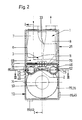
- a guide surface 86 which runs horizontally in the peripheral part and merges into a sleeve coaxial with the drive shaft 55 and projecting into the centrifuge interior 90, an outlet line 89 opens essentially tangentially (FIG. 3) the bowl.
- the centrifuge container 83 tapers downward to a bottom opening 84, through which the centrifuged solids get into the collecting bowl 77 placed on the lower part 76, in which, when the centrifuge 80 is at a standstill, any solids that flow away together with residual liquid settle out.
- the liquid rises in the centrifuge container 83 upwards and enters via an inwardly projecting ring flange 85 into an outer ring channel 88 of the lower part 76, the ring channel towards the collecting bowl 77 being covered by an outer ring flange 87 of the centrifuge container 83.
- the cleaned liquid then flows out via the drain channel 49 (FIG. 3), which, like the drain line 89 of the bowl, can be rotated into any position.
- the collecting pot 77 usually has a limited capacity, which is less than that of the collecting pot 6 of the settling container 1, the collecting pot 77 is also connected via a line 81 to the mixture inlet 7, the inlet opening being covered by a sieve 65.
- the separator housing 10 can be separated from the upper part 74 of the housing 72 in a simple manner as soon as the attachment 26 has been removed.
- the two pipe pieces 45 also form push-on parts for the secondary container 2, which carries lateral pins 73 on the upper side, which can be inserted from above into slots in the side walls of the housing 72.
- the air freed from the solids and the liquid is directed downwards along a wall section 27 extending in the extension of the partition 11 in the attachment 26, in a helix of a cyclone 38 around a central suction pipe 42, and then at the end through the suction pipe 42 back up and finally sucked through the clean air outlet 8 to the suction pump.
- the suction pipe 42 is through a closure body 41 closable, which is arranged on a rod 28 projecting upwardly through the suction pipe 42, which passes through the upper cover 29 of the attachment 26 and has a head 93 there, a compression spring 92 being arranged between the cover 29 and the head 93, so that the closure body 41 is acted upon in the closing direction.
- the upper cover 29 delimits a chamber 30 in which a membrane 31 is arranged and is under vacuum via a line 32 which is connected to the clean air outlet 8.
- the membrane 31 acts on the head 93 and holds the closure body 41 in the open position.
- a valve 69 is inserted into the line 32 and is operated via a control 54, to which a liquid level sensor 68 is assigned. If the liquid in the housing 10 rises into the air separation space 3, the valve 69 is actuated via the level sensor 68, which connects the chamber 30 to the outside air, so that the closure body 41 closes the suction pipe 42 under the action of the spring 92.
- the suction pump itself is also advantageously switched off at the same time.
- a collecting trough 94 around the cyclone 38 collects residual liquid and directs it into the housing 10, preferably into the sub-container 2 below.
Landscapes
- Health & Medical Sciences (AREA)
- Dentistry (AREA)
- Epidemiology (AREA)
- Life Sciences & Earth Sciences (AREA)
- Animal Behavior & Ethology (AREA)
- General Health & Medical Sciences (AREA)
- Public Health (AREA)
- Veterinary Medicine (AREA)
- Centrifugal Separators (AREA)
- Cyclones (AREA)
- Dental Preparations (AREA)
- Acyclic And Carbocyclic Compounds In Medicinal Compositions (AREA)
- Display Devices Of Pinball Game Machines (AREA)
- Toys (AREA)
- Separation Using Semi-Permeable Membranes (AREA)
- Apparatus For Radiation Diagnosis (AREA)
- Dental Tools And Instruments Or Auxiliary Dental Instruments (AREA)
- Eye Examination Apparatus (AREA)
- Vaporization, Distillation, Condensation, Sublimation, And Cold Traps (AREA)
Applications Claiming Priority (3)
| Application Number | Priority Date | Filing Date | Title |
|---|---|---|---|
| AT398684 | 1984-12-17 | ||
| AT3986/84 | 1984-12-17 | ||
| EP86900003A EP0242358B1 (fr) | 1984-12-17 | 1985-12-16 | Procede de separation d'un melange liquide-solide dentaire |
Related Parent Applications (1)
| Application Number | Title | Priority Date | Filing Date |
|---|---|---|---|
| EP86900003.4 Division | 1985-12-16 |
Publications (3)
| Publication Number | Publication Date |
|---|---|
| EP0432142A2 true EP0432142A2 (fr) | 1991-06-12 |
| EP0432142A3 EP0432142A3 (en) | 1991-07-31 |
| EP0432142B1 EP0432142B1 (fr) | 1995-05-10 |
Family
ID=3558107
Family Applications (4)
| Application Number | Title | Priority Date | Filing Date |
|---|---|---|---|
| EP86900003A Expired - Lifetime EP0242358B1 (fr) | 1984-12-17 | 1985-12-16 | Procede de separation d'un melange liquide-solide dentaire |
| EP91103249A Expired - Lifetime EP0441410B1 (fr) | 1984-12-17 | 1985-12-16 | Procédé pour séparer les particules solides-liquides d'un mélange dentaire |
| EP91103247A Expired - Lifetime EP0432142B1 (fr) | 1984-12-17 | 1985-12-16 | Séparateur dentaire |
| EP91103248A Expired - Lifetime EP0433270B1 (fr) | 1984-12-17 | 1985-12-16 | Séparateur et procédé pour séparer les particules solides de l'air d'aspiration |
Family Applications Before (2)
| Application Number | Title | Priority Date | Filing Date |
|---|---|---|---|
| EP86900003A Expired - Lifetime EP0242358B1 (fr) | 1984-12-17 | 1985-12-16 | Procede de separation d'un melange liquide-solide dentaire |
| EP91103249A Expired - Lifetime EP0441410B1 (fr) | 1984-12-17 | 1985-12-16 | Procédé pour séparer les particules solides-liquides d'un mélange dentaire |
Family Applications After (1)
| Application Number | Title | Priority Date | Filing Date |
|---|---|---|---|
| EP91103248A Expired - Lifetime EP0433270B1 (fr) | 1984-12-17 | 1985-12-16 | Séparateur et procédé pour séparer les particules solides de l'air d'aspiration |
Country Status (7)
| Country | Link |
|---|---|
| US (1) | US5018971A (fr) |
| EP (4) | EP0242358B1 (fr) |
| AT (4) | ATE134496T1 (fr) |
| AU (1) | AU5311886A (fr) |
| CA (1) | CA1293455C (fr) |
| DE (6) | DE3588017D1 (fr) |
| WO (1) | WO1986003669A1 (fr) |
Cited By (4)
| Publication number | Priority date | Publication date | Assignee | Title |
|---|---|---|---|---|
| DE4243239A1 (de) * | 1992-12-19 | 1994-06-23 | Schwarz Joerg Martin Dr | Vorrichtung zum Abscheiden von Amalgam |
| WO1994016643A1 (fr) * | 1993-01-22 | 1994-08-04 | Trawoeger Werner | Separateur a usage dentaire |
| WO1994018903A1 (fr) * | 1993-02-18 | 1994-09-01 | Trawoeger Werner | Procede et appareil pour la separation de l'air aspire transporteur et d'un fluide transporte |
| AT400512B (de) * | 1993-11-19 | 1996-01-25 | Trawoeger Werner | Abscheider |
Families Citing this family (38)
| Publication number | Priority date | Publication date | Assignee | Title |
|---|---|---|---|---|
| DE3633494C2 (de) * | 1986-10-02 | 1995-04-27 | Duerr Dental Gmbh Co Kg | Vorrichtung zum Abscheiden von feinen Feststoffpartikeln, insbesondere Amalgampartikeln, aus Abwasser |
| DE3860326D1 (de) * | 1987-05-13 | 1990-08-23 | Siemens Ag | Vorrichtung zum abscheiden von feststoffen aus fluessigkeiten in zahnaerztlichen einrichtungen. |
| CH675549A5 (fr) * | 1987-10-31 | 1990-10-15 | Emda | |
| AT389236B (de) | 1987-11-03 | 1989-11-10 | Trawoeger Werner | Abscheider |
| AT388285B (de) * | 1987-11-20 | 1989-05-26 | Trawoeger Werner | Abscheider |
| ATA209688A (de) * | 1988-08-25 | 1989-10-15 | Trawoeger Werner | Verfahren und einrichtung zur hintanhaltung von funktionsstoerungen einer zahnaerztlichen absauganlage |
| US4919826A (en) * | 1988-12-20 | 1990-04-24 | Air Techniques, Incorporated | Process and apparatus for separating solids and liquids from an effluent stream |
| US5032260A (en) * | 1988-12-20 | 1991-07-16 | Air Techniques Incorporated | Eductor system for water ring vacuum pump |
| SE469681B (sv) * | 1991-02-07 | 1993-08-23 | Boliden Contech Ab | Saett att minska risker foer kvicksilverskador i samband med tandbehandling |
| AT394952B (de) * | 1991-04-12 | 1992-08-10 | Trawoeger Werner | Abscheider zur trennung eines feststoff-fluessigkeitsgemisches |
| AT395941B (de) * | 1991-04-12 | 1993-04-26 | Trawoeger Werner | Abscheider zur trennung eines feststoff-fluessigkeitsgemisches |
| DE4117479A1 (de) * | 1991-05-28 | 1992-12-03 | Eitenmueller Klaus | Entleerbares sedimentiergefaess und verfahren zum entleeren eines sedimentiergefaesses |
| DE4143625B4 (de) * | 1991-07-03 | 2006-12-21 | Dürr Dental GmbH & Co. KG | Abscheideeinheit |
| IT1259318B (it) * | 1992-02-19 | 1996-03-11 | Cattani Spa | Separatore di particelle solide per portare variabili di fluidi di scarico di impianti odontoiatrici |
| US5428256A (en) * | 1992-12-08 | 1995-06-27 | Schloss Engineering Equipment, Inc. | Submersible motor enclosure |
| AT400393B (de) * | 1993-11-05 | 1995-12-27 | Trawoeger Werner | Abscheider |
| US5667382A (en) * | 1994-05-27 | 1997-09-16 | Holland; Robert S. | Vacuum pump seal-water recycling and waste disposal system for dental operatories |
| DE4420723A1 (de) * | 1994-06-15 | 1995-12-21 | Duerr Dental Gmbh Co Kg | Einrichtung zum Entfernen von Feststoffpartikeln aus einer Arbeitsflüssigkeit |
| AT401228B (de) * | 1995-02-09 | 1996-07-25 | Trawoeger Werner | Abscheider |
| US5788852A (en) * | 1997-04-18 | 1998-08-04 | Mescon; Howard Michael | Process for preventing accumulation of contaminants in dental suction systems |
| AT405366B (de) * | 1997-05-05 | 1999-07-26 | Pregenzer Bruno | Absaugeinrichtung für ein fliessfähiges medium |
| US6083306A (en) * | 1999-01-19 | 2000-07-04 | Cattani S.P.A. | Separator and discharger device for waste fluids in dental aspiration apparatus |
| US6276936B1 (en) | 1999-09-30 | 2001-08-21 | Michael Forster | Dental separator for solids from a solids/liquid mixture |
| US6083391A (en) * | 1999-05-20 | 2000-07-04 | Pregenzer; Bruno | Dental separator |
| US7306460B2 (en) * | 2001-06-25 | 2007-12-11 | Henry Hubner | Dental vacuum system assembly and process incorporating an amalgam separation chamber |
| US6790038B2 (en) * | 2001-06-25 | 2004-09-14 | Air Techniques, Inc. | Dental vacuum system assembly and process incorporating an amalgam separation chamber |
| WO2005032394A2 (fr) * | 2003-10-01 | 2005-04-14 | Ada Technologies, Inc. | Systeme pour enlever le mercure et les composes de mercure de dechets dentaires |
| FR2877208B1 (fr) * | 2004-10-28 | 2007-02-23 | Joseph Ohayon | Appareil d'hygiene bucco-dentaire et ensemble jetable |
| US20070172790A1 (en) * | 2006-01-26 | 2007-07-26 | Midmark Corporation | Dental Vacuum System |
| KR100746529B1 (ko) * | 2006-10-10 | 2007-08-06 | 주식회사 지피코 | 치과용 오염물 소독기 |
| DE102006058955B4 (de) * | 2006-12-12 | 2014-07-24 | DüRR DENTAL AG | Saugvorrichtung für dentale, medizinische und industrielle Zwecke |
| DE202010010802U1 (de) * | 2010-07-29 | 2011-11-02 | DüRR DENTAL AG | Feststoffabscheider |
| US11963836B2 (en) | 2016-10-12 | 2024-04-23 | Solmetex Llc | Detachable recycling container |
| US10779923B2 (en) | 2016-10-12 | 2020-09-22 | Solmetex, L.L.C. | Detachable recycling container |
| US11660175B2 (en) | 2016-05-23 | 2023-05-30 | Solmetex, Llc | Detachable recycling container |
| CA2982106C (fr) | 2016-10-12 | 2020-05-05 | Solmetex, Llc | Separation d'amalgame dentaire et systeme de recyclage |
| AT523129B1 (de) * | 2019-11-08 | 2022-07-15 | Pregenzer Bruno | Dentalabscheider |
| AT524360B1 (de) * | 2020-11-02 | 2023-01-15 | Pregenzer Bruno | Abscheider mit integriertem Dichtelement zur Flüssigkeit-Luft-Trennung |
Family Cites Families (38)
| Publication number | Priority date | Publication date | Assignee | Title |
|---|---|---|---|---|
| GB496998A (en) * | 1937-03-10 | 1938-12-12 | Erkensator G M B H | Improvements in and relating to centrifuges |
| US2759476A (en) * | 1954-12-08 | 1956-08-21 | Gomco Surgical Mfg Corp | Aspirating apparatus |
| US3051175A (en) * | 1960-02-29 | 1962-08-28 | Ritter Co Inc | Dental waste disposal system |
| US3078579A (en) * | 1960-10-28 | 1963-02-26 | Pelton & Crane Company | Dental aspirator with splash baffle |
| US3138873A (en) * | 1961-09-08 | 1964-06-30 | Harold P Bishop | Vacuum attachment for dental aspirator unit |
| GB1106858A (en) * | 1965-11-01 | 1968-03-20 | Electrolux Ab | Aspirator apparatus for dental purposes |
| GB1220255A (en) * | 1967-06-07 | 1971-01-27 | Chirana Zd Y Zdravotnicke Tech | Improvements in or relating to suction devices |
| US3665682A (en) * | 1970-08-06 | 1972-05-30 | Pennwalt Corp | Dental evacuation apparatus |
| US3847573A (en) * | 1971-03-10 | 1974-11-12 | S Gandrud | Dental office system |
| SE375701B (fr) * | 1972-08-23 | 1975-04-28 | B I F Ritzler | |
| US3777403A (en) * | 1972-09-18 | 1973-12-11 | J Ritchie | Dental silver retrieval apparatus |
| US3861584A (en) * | 1973-06-20 | 1975-01-21 | Donaldson Co Inc | Self-purging centrifuge |
| DE2459881B2 (de) * | 1974-12-18 | 1979-04-12 | Siemens Ag, 1000 Berlin Und 8000 Muenchen | Zahnärztliches Gerät mit einer Absaugvorrichtung |
| DE2713321C2 (de) * | 1977-03-25 | 1987-02-26 | Dürr-Dental GmbH & Co KG, 7120 Bietigheim-Bissingen | Verfahren und Vorrichtung zum Abscheiden von flüssigen und festen Bestandteilen aus dem aus dem Mund eines Patienten kommenden Saugmediengemisch |
| IT1124255B (it) * | 1979-01-15 | 1986-05-07 | Augusto Cattani & C Sas Off | Dispositivo separatore e scaricatore di liquido per impianti di aspirazione di fluidi in particolare per impianti per gabinetti odonto iatrici |
| SE427988B (sv) * | 1979-03-08 | 1983-05-30 | Bjorn Ekman | Anordning for avskiljning av tunga metaller fran avloppsvatten, foretredesvis i tandlekarpraktik |
| US4234325A (en) * | 1979-03-19 | 1980-11-18 | Dresser Industries, Inc. | Silencer-separator with internal trap for liquid seal blowers or the like |
| DE2929804C2 (de) * | 1979-07-23 | 1985-10-03 | Siemens AG, 1000 Berlin und 8000 München | Zahnärztliche Absaugeinrichtung |
| SE440071B (sv) * | 1979-08-17 | 1985-07-15 | Scania Dental | Apparat av centrifugtyp for avskiljning av fasta partiklar fran avfallsvatten |
| US4332560A (en) * | 1980-03-10 | 1982-06-01 | Rait Joseph M | Particle collector for use with dental suction apparatus |
| US4385891A (en) * | 1981-04-09 | 1983-05-31 | Ligotti Eugene F | Dental apparatus for preventing loss of precious metal particles |
| DE3145838A1 (de) * | 1981-11-19 | 1983-05-26 | Siemens AG, 1000 Berlin und 8000 München | "zahnaerztliche absaugeinrichtung" |
| DK156880C (da) * | 1982-02-05 | 1990-03-12 | Horn Lassen Hans | Apparat til udskillelse af affaldsstoffer fra en stroem af vaeske og gas |
| SE8203454L (sv) * | 1982-06-04 | 1983-12-05 | Ernryd Leif Ab | Anordning for avskiljning av fasta partiklar fran en vetska |
| DE3231272A1 (de) * | 1982-08-23 | 1984-02-23 | Siemens AG, 1000 Berlin und 8000 München | Zahnaerztliche absaugeinrichtung |
| DE3242212A1 (de) * | 1982-11-15 | 1984-05-17 | Siemens AG, 1000 Berlin und 8000 München | Zahnaerztliche absaugeinrichtung |
| NL8401573A (nl) * | 1983-05-17 | 1984-12-17 | Renneberg Johann | Werkwijze en inrichting voor de behandeling van gassen en dampen. |
| DE8314829U1 (de) * | 1983-05-19 | 1983-10-06 | Jerzy, Ingo, 2056 Glinde | Schwerkraftabscheider fuer absauggeraete fuer zahnaerzte |
| SE442829B (sv) * | 1984-06-20 | 1986-02-03 | Scania Dental | Apparat for att separera luft och fasta partiklar fran en vetska |
| GB2160786B (en) * | 1984-06-26 | 1988-03-23 | Broadbent & Sons Ltd Thomas | Separating systems |
| IT1187187B (it) * | 1985-07-31 | 1987-12-16 | Cattani Off Augusto & Co | Dispositivo separatore e scaricatore di liquidi con pompa di drenaggio,in particolare per impianti di aspirazione odontoiatrici |
| DE3542134A1 (de) * | 1985-11-28 | 1987-06-04 | Duerr Dental Gmbh Co Kg | Geraet zum abscheiden feiner feststoffpartikel aus abwasser |
| DE3542115A1 (de) * | 1985-11-28 | 1987-06-04 | Duerr Dental Gmbh Co Kg | Vollmantel-zentrifuge zum abscheiden feiner feststoffpartikel aus abwasser |
| DE3542133A1 (de) * | 1985-11-28 | 1987-06-04 | Duerr Dental Gmbh Co Kg | Geraet zum abscheiden feiner feststoffpartikel aus abwasser |
| DE3542114A1 (de) * | 1985-11-28 | 1987-06-04 | Duerr Dental Gmbh Co Kg | Zentrifuge zum abscheiden feiner feststoffpartikel aus abwasser |
| DE3601254C2 (de) * | 1986-01-17 | 1995-05-04 | Duerr Dental Gmbh Co Kg | Zahnärztliche Absaugeinrichtung |
| DE3633494C2 (de) * | 1986-10-02 | 1995-04-27 | Duerr Dental Gmbh Co Kg | Vorrichtung zum Abscheiden von feinen Feststoffpartikeln, insbesondere Amalgampartikeln, aus Abwasser |
| DE8702001U1 (de) * | 1987-02-10 | 1987-03-26 | Pregenzer, Bruno, Oberperfuß | Abscheider |
-
1985
- 1985-12-16 DE DE3588017T patent/DE3588017D1/de not_active Expired - Fee Related
- 1985-12-16 EP EP86900003A patent/EP0242358B1/fr not_active Expired - Lifetime
- 1985-12-16 DE DE8590187U patent/DE8590187U1/de not_active Expired
- 1985-12-16 DE DE3588000T patent/DE3588000D1/de not_active Expired - Fee Related
- 1985-12-16 CA CA000497756A patent/CA1293455C/fr not_active Expired - Lifetime
- 1985-12-16 EP EP91103249A patent/EP0441410B1/fr not_active Expired - Lifetime
- 1985-12-16 DE DE8686900003T patent/DE3584636D1/de not_active Expired - Lifetime
- 1985-12-16 AT AT91103249T patent/ATE134496T1/de not_active IP Right Cessation
- 1985-12-16 DE DE3588087T patent/DE3588087D1/de not_active Expired - Fee Related
- 1985-12-16 EP EP91103247A patent/EP0432142B1/fr not_active Expired - Lifetime
- 1985-12-16 WO PCT/AT1985/000057 patent/WO1986003669A1/fr not_active Ceased
- 1985-12-16 EP EP91103248A patent/EP0433270B1/fr not_active Expired - Lifetime
- 1985-12-16 AT AT86900003T patent/ATE69151T1/de not_active IP Right Cessation
- 1985-12-16 AT AT91103247T patent/ATE122223T1/de not_active IP Right Cessation
- 1985-12-16 AT AT91103248T patent/ATE119378T1/de active
- 1985-12-16 AU AU53118/86A patent/AU5311886A/en not_active Abandoned
- 1985-12-16 DE DE8536837U patent/DE8536837U1/de not_active Expired
-
1989
- 1989-06-22 US US07/370,152 patent/US5018971A/en not_active Expired - Lifetime
Cited By (5)
| Publication number | Priority date | Publication date | Assignee | Title |
|---|---|---|---|---|
| DE4243239A1 (de) * | 1992-12-19 | 1994-06-23 | Schwarz Joerg Martin Dr | Vorrichtung zum Abscheiden von Amalgam |
| WO1994016643A1 (fr) * | 1993-01-22 | 1994-08-04 | Trawoeger Werner | Separateur a usage dentaire |
| AT399457B (de) * | 1993-01-22 | 1995-05-26 | Trawoeger Werner | Zahnärztlicher abscheider |
| WO1994018903A1 (fr) * | 1993-02-18 | 1994-09-01 | Trawoeger Werner | Procede et appareil pour la separation de l'air aspire transporteur et d'un fluide transporte |
| AT400512B (de) * | 1993-11-19 | 1996-01-25 | Trawoeger Werner | Abscheider |
Also Published As
| Publication number | Publication date |
|---|---|
| DE3588000D1 (de) | 1995-04-13 |
| EP0242358A1 (fr) | 1987-10-28 |
| US5018971A (en) | 1991-05-28 |
| ATE134496T1 (de) | 1996-03-15 |
| DE3588017D1 (de) | 1995-06-14 |
| ATE69151T1 (de) | 1991-11-15 |
| EP0432142B1 (fr) | 1995-05-10 |
| EP0433270A3 (en) | 1991-08-14 |
| EP0242358B1 (fr) | 1991-11-06 |
| EP0441410B1 (fr) | 1996-02-28 |
| DE3588087D1 (de) | 1996-04-04 |
| AU5311886A (en) | 1986-07-22 |
| ATE122223T1 (de) | 1995-05-15 |
| DE8536837U1 (de) | 1987-12-10 |
| DE8590187U1 (de) | 1987-12-10 |
| EP0441410A1 (fr) | 1991-08-14 |
| EP0433270B1 (fr) | 1995-03-08 |
| WO1986003669A1 (fr) | 1986-07-03 |
| DE3584636D1 (de) | 1991-12-12 |
| ATE119378T1 (de) | 1995-03-15 |
| EP0433270A2 (fr) | 1991-06-19 |
| CA1293455C (fr) | 1991-12-24 |
| EP0432142A3 (en) | 1991-07-31 |
Similar Documents
| Publication | Publication Date | Title |
|---|---|---|
| EP0432142B1 (fr) | Séparateur dentaire | |
| EP0579705B1 (fr) | Separateur pour melange liquide-solide | |
| DE69306433T2 (de) | Abscheider fester Partikel für den variablen Abzug von Flüssigkeitsströmen in einem zahnärztlichen Apparat | |
| EP0237708B2 (fr) | Dispositif d'aspiration dentaire | |
| EP0678008B1 (fr) | Separateur | |
| DE3916742C2 (de) | Abscheideeinheit | |
| JP3448565B2 (ja) | 分離機の自己放出型遠心ドラムから回収された固体の液体含有量を調整する方法および装置 | |
| EP0387262B1 (fr) | Separateur | |
| EP0224232B1 (fr) | Centrifugeuse à paroi pleine pour la séparation de particules solides fines | |
| DE8536838U1 (de) | Abscheider | |
| SE445036B (sv) | Anordning for rening av avloppsvatten innehallande olja och/eller andra fororeningar | |
| WO1994016643A1 (fr) | Separateur a usage dentaire | |
| DE3726394C2 (de) | Separator | |
| EP0387263A1 (fr) | Separateur centrifuge. | |
| AT510883B1 (de) | Abscheider zum abscheiden von feststoffen aus einem zahnärztlichen abwassergemisch | |
| DE4102695A1 (de) | Feststoff-abscheidevorrichtung | |
| DE102006012312B4 (de) | Zentrifuge zum Abscheiden feiner Partikel aus einem Fluid | |
| CN218774406U (zh) | 一种对向式折叠滤袋固液分离装置 | |
| AT501623B1 (de) | Zentrifuge zum abscheiden feiner partikel aus einem fluid | |
| WO1993015843A1 (fr) | Procede pour utiliser en continu un separateur et accessoires pour ledit separateur | |
| DE8126650U1 (de) | Vorrichtung zum abscheiden von sink und/oder schwimmstoffen, insbesondere sand |
Legal Events
| Date | Code | Title | Description |
|---|---|---|---|
| PUAI | Public reference made under article 153(3) epc to a published international application that has entered the european phase |
Free format text: ORIGINAL CODE: 0009012 |
|
| AC | Divisional application: reference to earlier application |
Ref document number: 242358 Country of ref document: EP |
|
| AK | Designated contracting states |
Kind code of ref document: A2 Designated state(s): AT BE CH DE FR GB IT LI NL SE |
|
| PUAL | Search report despatched |
Free format text: ORIGINAL CODE: 0009013 |
|
| AK | Designated contracting states |
Kind code of ref document: A3 Designated state(s): AT BE CH DE FR GB IT LI NL SE |
|
| 17P | Request for examination filed |
Effective date: 19910705 |
|
| 17Q | First examination report despatched |
Effective date: 19941024 |
|
| GRAA | (expected) grant |
Free format text: ORIGINAL CODE: 0009210 |
|
| ITF | It: translation for a ep patent filed | ||
| AC | Divisional application: reference to earlier application |
Ref document number: 242358 Country of ref document: EP |
|
| AK | Designated contracting states |
Kind code of ref document: B1 Designated state(s): AT BE CH DE FR GB IT LI NL SE |
|
| REF | Corresponds to: |
Ref document number: 122223 Country of ref document: AT Date of ref document: 19950515 Kind code of ref document: T |
|
| GBT | Gb: translation of ep patent filed (gb section 77(6)(a)/1977) |
Effective date: 19950516 |
|
| REF | Corresponds to: |
Ref document number: 3588017 Country of ref document: DE Date of ref document: 19950614 |
|
| ET | Fr: translation filed | ||
| PG25 | Lapsed in a contracting state [announced via postgrant information from national office to epo] |
Ref country code: GB Effective date: 19951216 Ref country code: AT Effective date: 19951216 |
|
| PG25 | Lapsed in a contracting state [announced via postgrant information from national office to epo] |
Ref country code: SE Effective date: 19951217 |
|
| PG25 | Lapsed in a contracting state [announced via postgrant information from national office to epo] |
Ref country code: LI Effective date: 19951231 Ref country code: CH Effective date: 19951231 Ref country code: BE Effective date: 19951231 |
|
| PLBE | No opposition filed within time limit |
Free format text: ORIGINAL CODE: 0009261 |
|
| STAA | Information on the status of an ep patent application or granted ep patent |
Free format text: STATUS: NO OPPOSITION FILED WITHIN TIME LIMIT |
|
| 26N | No opposition filed | ||
| BERE | Be: lapsed |
Owner name: PREGENZER BRUNO Effective date: 19951231 Owner name: TRAWOGER WERNER Effective date: 19951231 |
|
| PG25 | Lapsed in a contracting state [announced via postgrant information from national office to epo] |
Ref country code: NL Effective date: 19960701 |
|
| GBPC | Gb: european patent ceased through non-payment of renewal fee |
Effective date: 19951216 |
|
| REG | Reference to a national code |
Ref country code: CH Ref legal event code: PL |
|
| PG25 | Lapsed in a contracting state [announced via postgrant information from national office to epo] |
Ref country code: FR Effective date: 19960830 |
|
| NLV4 | Nl: lapsed or anulled due to non-payment of the annual fee |
Effective date: 19960701 |
|
| REG | Reference to a national code |
Ref country code: FR Ref legal event code: ST |
|
| PGFP | Annual fee paid to national office [announced via postgrant information from national office to epo] |
Ref country code: DE Payment date: 20000131 Year of fee payment: 15 |
|
| PG25 | Lapsed in a contracting state [announced via postgrant information from national office to epo] |
Ref country code: DE Free format text: LAPSE BECAUSE OF NON-PAYMENT OF DUE FEES Effective date: 20011002 |