EP0429434A2 - Druckeinstellvorrichtung für Tintenstrahldrucker - Google Patents
Druckeinstellvorrichtung für Tintenstrahldrucker Download PDFInfo
- Publication number
- EP0429434A2 EP0429434A2 EP91101791A EP91101791A EP0429434A2 EP 0429434 A2 EP0429434 A2 EP 0429434A2 EP 91101791 A EP91101791 A EP 91101791A EP 91101791 A EP91101791 A EP 91101791A EP 0429434 A2 EP0429434 A2 EP 0429434A2
- Authority
- EP
- European Patent Office
- Prior art keywords
- ink
- air
- ink jet
- recording apparatus
- jet recording
- Prior art date
- Legal status (The legal status is an assumption and is not a legal conclusion. Google has not performed a legal analysis and makes no representation as to the accuracy of the status listed.)
- Granted
Links
Images


Classifications
-
- B—PERFORMING OPERATIONS; TRANSPORTING
- B41—PRINTING; LINING MACHINES; TYPEWRITERS; STAMPS
- B41J—TYPEWRITERS; SELECTIVE PRINTING MECHANISMS, i.e. MECHANISMS PRINTING OTHERWISE THAN FROM A FORME; CORRECTION OF TYPOGRAPHICAL ERRORS
- B41J2/00—Typewriters or selective printing mechanisms characterised by the printing or marking process for which they are designed
- B41J2/005—Typewriters or selective printing mechanisms characterised by the printing or marking process for which they are designed characterised by bringing liquid or particles selectively into contact with a printing material
- B41J2/01—Ink jet
- B41J2/07—Ink jet characterised by jet control
-
- B—PERFORMING OPERATIONS; TRANSPORTING
- B41—PRINTING; LINING MACHINES; TYPEWRITERS; STAMPS
- B41J—TYPEWRITERS; SELECTIVE PRINTING MECHANISMS, i.e. MECHANISMS PRINTING OTHERWISE THAN FROM A FORME; CORRECTION OF TYPOGRAPHICAL ERRORS
- B41J2/00—Typewriters or selective printing mechanisms characterised by the printing or marking process for which they are designed
- B41J2/005—Typewriters or selective printing mechanisms characterised by the printing or marking process for which they are designed characterised by bringing liquid or particles selectively into contact with a printing material
- B41J2/01—Ink jet
- B41J2/015—Ink jet characterised by the jet generation process
- B41J2/04—Ink jet characterised by the jet generation process generating single droplets or particles on demand
- B41J2/06—Ink jet characterised by the jet generation process generating single droplets or particles on demand by electric or magnetic field
-
- B—PERFORMING OPERATIONS; TRANSPORTING
- B41—PRINTING; LINING MACHINES; TYPEWRITERS; STAMPS
- B41J—TYPEWRITERS; SELECTIVE PRINTING MECHANISMS, i.e. MECHANISMS PRINTING OTHERWISE THAN FROM A FORME; CORRECTION OF TYPOGRAPHICAL ERRORS
- B41J2/00—Typewriters or selective printing mechanisms characterised by the printing or marking process for which they are designed
- B41J2/005—Typewriters or selective printing mechanisms characterised by the printing or marking process for which they are designed characterised by bringing liquid or particles selectively into contact with a printing material
- B41J2/01—Ink jet
- B41J2/17—Ink jet characterised by ink handling
- B41J2/175—Ink supply systems ; Circuit parts therefor
-
- B—PERFORMING OPERATIONS; TRANSPORTING
- B41—PRINTING; LINING MACHINES; TYPEWRITERS; STAMPS
- B41J—TYPEWRITERS; SELECTIVE PRINTING MECHANISMS, i.e. MECHANISMS PRINTING OTHERWISE THAN FROM A FORME; CORRECTION OF TYPOGRAPHICAL ERRORS
- B41J2/00—Typewriters or selective printing mechanisms characterised by the printing or marking process for which they are designed
- B41J2/005—Typewriters or selective printing mechanisms characterised by the printing or marking process for which they are designed characterised by bringing liquid or particles selectively into contact with a printing material
- B41J2/01—Ink jet
- B41J2/015—Ink jet characterised by the jet generation process
- B41J2/04—Ink jet characterised by the jet generation process generating single droplets or particles on demand
- B41J2/06—Ink jet characterised by the jet generation process generating single droplets or particles on demand by electric or magnetic field
- B41J2002/061—Ejection by electric field of ink or of toner particles contained in ink
-
- B—PERFORMING OPERATIONS; TRANSPORTING
- B41—PRINTING; LINING MACHINES; TYPEWRITERS; STAMPS
- B41J—TYPEWRITERS; SELECTIVE PRINTING MECHANISMS, i.e. MECHANISMS PRINTING OTHERWISE THAN FROM A FORME; CORRECTION OF TYPOGRAPHICAL ERRORS
- B41J2202/00—Embodiments of or processes related to ink-jet or thermal heads
- B41J2202/01—Embodiments of or processes related to ink-jet heads
- B41J2202/02—Air-assisted ejection
Definitions
- This invention relates generally to ink jet recording apparatus for recording letters and/or pictures on a recording medium by an ink-discharge using an airflow, and which responds to an electric signal, and particularly to an ink jet recording apparatus with pressure adjustable mechanisms for discharging a constant ink amount.
- ink jet printers have advantages such as noiselessness, ease of application to color printers, and high picture quality.
- methods for discharging ink the use of an airflow and an electrostatic force bring about a superior response.
- ink jet printers are known, and one example of the ink jet printers is disclosed in United States Patent No. 4,403,234.
- a conventional ink jet recording apparatus using an airflow and an electrostatic force comprises a nonconductive air nozzle plate having an air nozzle and a conductive ink nozzle plate being set in parallel with the air nozzle plate.
- the air nozzle plate has an electrode and has an ink nozzle for keeping an ink meniscus.
- the electrode and the conductive ink nozzle plate are connected to a signal source to establish an elctric field gradient therebetween.
- the ink nozzle plate and the air nozzle plate are secured to a rear housing to define an ink chamber and an annular airflow chamber.
- the ink chamber is connected to an ink tank for storing ink therein through an ink pipe, and the ink receives a constant pressure by a pressure regulator regulating a pressurized air from the air supply source.
- the pressurized air from an air supply source flows into the annular airflow chamber via an air pipe, and then flows out via the air nozzle.
- Such airstream makes a sharp pressure gradient at an annular laminar-airflow space between the ink nozzle and the air nozzle. Owing to the electric field gradient and the sharp pressure gradient, the meniscus is extended and discharged via the air nozzle.
- a condition of the meniscus is influenced by a difference between the level of the ink in the ink tank and the level of the ink nozzle, and by a distance between the air nozzle plate and the ink nozzle plate.
- the difference and the distance give great influence to recording characteristics including a record response of ink jet printing head and a threshold voltage, i.e. the minimum voltage for ink-discharge. Therefore, the difference and the distance have to be set to an optimum value such that an ink meniscus formed at the ink nozzle is in a convex shape.
- the present invention has been developed in order to remove the above-described drawbacks inherent to the conventional ink jet recording apparatus.
- an object of the present invention to provide new and useful ink jet recording apparatus with pressure adjustable mechanisms so that the amount of the discharging ink is constant, or does not decrease in accordance with the amount of remaining ink.
- an ink jet recording apparatus comprising a detachable air adjusting member having a smaller inside cross-sectional area than that of connecting means between the air supply source and the ink jet printing head, and an ink tank having introducing means having a duct and an air chamber.
- a printing head 30 comprises an air nozzle plate 2 having an air nozzle 1 and an ink nozzle plate 3 being set in parallel with the air nozzle plate 2.
- the air nozzle plate 2 is made of a nonconductive material and secured to a rear housing 31 made of a nonconductive material.
- the ink nozzle plate 3 is made of a conductive material and secured to the rear housing 31.
- the air nozzle plate 2 has an electrode 14, and the ink nozzle plate 3 has an ink nozzle 4 for keeping an ink meniscus.
- the ink nozzle plate 3 and the rear housing 31 define an ink chamber 10.
- the air nozzle plate 2, the ink nozzle plate 3, and the rear housing 31 define an annular airflow chamber 9.
- the ink chamber 10 is connected, through an ink line or an ink pipe 6, to an ink tank 11 for storing ink 26 therein, and the ink 26 receives a constant pressure by a pressure regulator 13 regulating a pressurized air from an air supply source 12.
- the pressurized air flows into the annular airflow chamber 9 via an air line or an air pipe 8, and then flows out via the air nozzle 1.
- Such airstream makes a sharp pressure gradient at an annular laminar-airflow space 7 between the ink nozzle 4 and the air nozzle 1.
- a signal source 5 is connected to an electrode 14 and the conductive ink nozzle plate 3 thereby developing an electric potential difference between the air nozzle 1 and the ink nozzle 4. Therefore, the ink meniscus is streched out in the direction to the air nozzle 1 by the electric potential difference and is torn off along the sharp pressure gradient made by the airflow in the annular laminar-airflow space 7. Owing to effects of the electrostatic force and the sharp gradient, the ink meniscus is discharged via the air nozzle 1.
- Reference “h” is difference between the level of the ink nozzle 4 and the ink level in the ink tank 11.
- a distance between the ink nozzle plate 3 and ink nozzle plate 2, i.e. "thickness" of the annular laminar- airflow space 7 gives greate influence to record characteristics including a record response of ink jet printing head and a threshold voltage, i.e. the minimum voltage for ink-discharge. Therefore, the distance have to be set to an optimum value such that an ink meniscus formed at the ink nozzle is in a convex shape. According to experiments, this distance is preferably set to approximately 10 ⁇ m to obtain satisfactory recording characteristics. Owing to this, there is an adjustment by a distance between the air nozzle plate 2 and the ink nozzle plate 3.
- the difference "h” does not assume a constant value, or varies among the ink jet heads. This is because the distance of the annular laminar-airflow space 7 usually differs throughout a plurality of heads due to difficulty in practical manufacturing processes. As described before, the difference "h” gives influence to ink-discharge. Namely, it is easy to discharge the ink 26 when the difference "h” comes to large, so that the amount of discharging ink is increased. On the contrary, the amount of the discharging ink is decreased when the difference "h” comes to small.
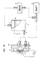
- FIG. 1A there is shown an ink jet printing head and its associated devices according to the first embodiment of the present invention.
- the same or corresponding elements and parts are designated at like reference numerals throughout the drawings.
- a printing head 30 comprises an air nozzle plate 2 having an air nozzle 1 and an ink nozzle plate 3 being set in parallel with the air nozzle plate 2.
- the air nozzle plate 2 is made of a nonconductive material and secured to a rear housing 31 made of a nonconductive material.
- the ink nozzle plate 3 is made of a conductive material and secured to the rear housing 31.
- the air nozzle plate 2 has an elctrode 14, and the ink nozzle plate 3 has an ink nozzle 4 for keeping an ink meniscus.
- the electrode 14 and the conductive ink nozzle plate 3 are connected to a signal source 5 to establish an elctricfield gradient therebetween.
- the ink nozzle plate 3 and the rear housing 31 define an ink chamber 10.
- the air nozzle plate 2, the ink nozzle plate 3, and the rear housing 31 define an annular airflow chamber 9.
- the ink chamber 10 is connected, through an ink line or an ink pipe 6, to an ink tank 11 for storing ink 26 therein, and the ink 26 receives a constant pressure by a pressure regulator 13 regulating a pressurized air from an air supply source 12.
- the pressurized air flows into the annular airflow chamber 9 via an air line or an air pipe 8 and an air adjusting member 16, and then flows out via the air nozzle 1.
- Such airstream makes a sharp pressure gradient at an annular laminar-airflow space 7 between the ink nozzle 4 and the air nozzle 1. Owing to the electric field gradient and the sharp pressure gradient, the meniscus is extended and discharged via the air nozzle 1.
- the air adjusting member 16 is set with an O-ring 15 to make a uniform airflow in the annular airflow chamber 9.
- the air adjustng member 16 may be pipy, and has a small inside cross-sectional area in comparison with the air pipe 8. It is to be noted that the air adjusting member 16 is detachablly provided so as to be another air adjusting member having a different inside cross-sectional area. More specifically, a plurality of air adjusting members 16 each having different inside cross-sectional area are prepared so that one of them is selectively used to establish an optimum balance between the outer surface of the meniscus and the ink chamber 10. While the length of the plurality of the air adjusting pipes 16 is approximately 10mm, the inner-diameters of the same are successively different by 0.1mm for example.
- Reference “h” is a difference between the level of the ink 26 in the ink tank 11 and the level of the ink nozzle 4.
- a condition of the meniscus is influenced by the difference "h”. Namely, it is easy to discharge the ink 26 when the difference "h” is large, so that the amount of discharging ink is increased. On the contrary, the amount of discharging ink is decreased when the difference "h” is small.
- the difference "h” is required to change by only 10 to 20mm when the pipe inner-diameter is changed by 0.1mm.
- the air adjusting member 16 set at near the ink jet printing head 30 brings about pressure loss by resistance generated at the time when the airflow passes through the air adjusting pipe 16.
- two elements of a length and an inside cross-sectional area of the air adjusting pipe 16 influence the pressure loss by the airflow, the adjustment by the inside cross-sectional area is better than the adjustment by the pipe length. This is because the pipe length cannot be set to a large value in practical. As a matter of fact, the adjustment may be controlled by both elements.
- the air adjusting pipe 16 is preferably close to head, because the airflow in the head is influenced by the pressure regulator 13 if the pipe 16 is set nearby the air supply 12.
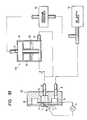
- Fig. 1B is a schematic view showing an ink discharging system of an ink jet recording apparatus according to the second embodiment of the present invention.
- the ink discharging system differs from Fig. 1A only in the following points.
- the air adjusting pipe 16 shown in Fig. 1A is absent, and another ink tank 11a is applied instead the ink tank 11 shown in Fig. 1A.
- the ink tank 11a is shown in Fig. 2.
- the pressurized air from the air supply source 12 flows into an air chamber 18 through an air inlet 17 in order to pressurize the ink 26 in an ink storage 19 via an air introducing means, such as a pipe or an air introducing duct 20 which extends to almost the bottom of the ink tank 11a.
- the ink 26 in the ink storage 19 is supplied from an ink outlet 21 to the ink chamber 10 in the ink jet printing head 30 via the ink pipe 6.
- an air pressure Pa from the air supply source 12 is applied to the ink tank 11a and the ink jet printing head 30 to make a stable meniscus at the ink nozzle 4, thereby pressing the ink 26 in the ink storage 19 through the air introducing duct 20.
- the same amount of air as the spending ink 26 flows out from the air introducing duct 20 so that ink level which substantially affects the ink jet printing head 30 assumes at the height O of the lower end of the air introducing duct 20. Therefore, the liquid level in the ink atorage 19 is always kept at the height O in spite of the amount of the remaining ink 26 in the ink storage 19.
- a reference ⁇ is the density of the ink 26
- a reference g is the gravitational acceleration
- a reference H is the height of level A relative to level O.
- the ink tank according to the present invention has an air introducing means such as a pipe or duct, whereby the pressure head at the ink level substantally affecting the ink jet printing head can be established to a constant value at the height O.
- Fig. 1C is a schematic view showing an ink discharging system of an ink jet recording apparatus according to the third embodiment of the invention.
- the first embodiment of Fig. 1A and the second embodiment of Fig. 2 are combined. Therefore, the above-mentioned effects of the use of the air adjusting pipe 16 and the use of the ink tank 11a can be obtained, so that the recording characteristics are further improved.
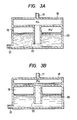
- Fig. 3A illustrates a pressurized ink tank 11a
- Fig. 3B shows a non-pressurized ink tank 11a used in the invention.
- the air pressure Pa is applied to the air chamber 18, and the air pressure Pa' is applied to the upper portion of the ink storage 19. If the air pressure Pa is not applied to the ink tank 11a, the value of the pressure Pa is decreased to the value of an atmospheric pressure Po so that the air pressure Pa' is also decreased. Therefore, the ink 26 in the ink storage 19 flows into the air chamber 18 as shown in Fig. 3B. Owing to such flown ink, the air chamber 18 is provided, and operates so as to prevent the ink 26 in the ink storage 19 from flowing out via the air inlet 17.
- an actual minimum capacity of the air chamber 18 can be determined by the capacity of the ink storage 19 and the magnitude of the air pressure Pa.
- V' is the air volume of the upper portion in the ink storage 19 as shown in Fig. 3A
- V2 Pa/Po ⁇ V'
- Fig. 4 is an illustration of a modified ink tank used in the invention.
- the pressurized air from the air supply source 12 flows into an air chamber 218 through an air inlet 17 to pressurize the ink 26 in an ink storage 219 via an air introducing duct 220.
- the end of the air introducing duct 220 is obliquely cut so as to look upward such that the pressurized air is easy to flow out of a large opening in response to the consumption of the ink 26. More specifically, since bubbles at the end of the air introducing duct 220 is difficult to enter the liquid when the cross-sectional area of the opening at the the end of the air introducing duct 220 is small, this cross-sectional area is made large by the above-mentioned oblique configulation.
- the configulation of the contact surface between the pressurized air and the ink 26 in the ink storage 219 different at the time between just before and just after the bubbles flow out from the air introducing duct 220.
- the air introducing duct 220 extends to almost the bottom of an ink tank 11b and further extends in the horizontal direction, it is able to keep the height O constant which is established at a contact position between the pressurized air and the ink in the ink storage 219. This is because the contact surface is shifted or moved only in the horizontal direction even if the ink tank is impacted or vibrated.
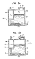
- the ink level which substantially affects the ink jet printing head 30 is established at the position as shown in Fig. 5B if the pressurized air is applied to the ink 26.
- the height B being established by the liquid level of the ink 26 which flows into the air chamber 218 is a substantial ink level while the pressurized air is not aplied.
- the height B changes in accordance with the amount of the remaining ink, the height B is not constant. therefore, the pressure head acting on the ink jet printing head is not constant while the ink jet recording apparatus is not operated in which no air pressure is applied.
- the substantial ink level in the ink tank is generally preferably lower than the ink nozzle level because a droplet from the ink nozzle 4 is brought about by the height difference therebetween wherein the ink nozzle level is lower than the the substantial ink level. Accordingly, in the construction of the embodiment of the invention, the height B should not be too much higher than the height O.
- FIG. 6 illustrates another modified ink tank 11c used in the invention.
- An air introducing pipe 320 is spiral for example, and may be made of a flexible material.
- the air introducing pipe 320 is also used itself for an air chamber corrisponding to the air chamber 18 or 218 because the air introducing pipe 320 can be sufficiently extended so that the volume of the air introducing pipe 320 can be increased. As a result, any other air chamber is not required in such example.
- Fig. 7 is an explanatory diagram showing a method for supplying the ink 26 according to the invention.
- the ink tank 11b has an opening 41 for supplying ink 26.
- the opening 41 is closed by a cap 22 during operation of the ink jet recording apparatus.
- the opening 41 and cap 22 shown in Fig.7 are not shown in Figs. 1A, 1B, 1C, 2, 3A, 3B and 6.
- the cap is taken off and a tube 23 which connects the air supply source 12 to the air outlet 17 is closed by a block instrument 24 such as a clip, in order to seal the air chamber 218.
- the air in the air chamber 218 comes to an atmospheric pressure when the cap 22 is taken off, and then the ink level comes to a given level with the ink 26 flowing into the air chamber 218.
- the ink level is preset in the air chamber 218 as such when the ink 26 is supplied, such an ink level hardly lowers, i.e. the air is not introduced to the air introducing pipe 220 even when the pressurized air is resupplied to the air chamber 218. This is because the volume of the air at the upper portion in the ink storage 219 is small after the ink 26 is supplied, that is to say, the amount of the contractable air in the ink storage 219, is small.
- the ink level which substantially affects the ink jet printing head 30 is established in the air chamber 218 until at least the same ink amount as the flowing ink into the air chamber 218 is expended. As a result, it means that the ink level substantially influencing ink jet printing head 30 is lowered or changed, i.e. the difference "h" is not constant.
- the ink 26 in an ink bottle 25 is led into the ink storage 219 from the opening 41.
- the ink does not flow into the air chamber 218.
- the supplied ink 26 comes to the condition of the ink 26 as shown in Fig. 5A when the pressurized air is resupplied to the tank 11b.
- the ink 26 is supplied to ink tank 11b from the opening 41 after the air inlet 17 and the ink outlet 21 are closed.
- the substantial ink level in the ink tank is established a certain value.
- ink jet recording apparatus with pressure adjustable mechanisms having a simple structure without moving the ink tank in response to the amount of remaining ink, and keeping all of uniform height between the ink level in the ink tanks and corresponding ink nozzles in a multi-head, without deterioration of recording characteristics.
- the present invention can also be applied to recording apparatus having printing heads using an airflow and a duration by a piezoelectric device, and one example of such recording apparatus is described in United States Patent No. 4,106,032. In this cace, the electric field gradient may not be required.
Landscapes
- Ink Jet (AREA)
- Particle Formation And Scattering Control In Inkjet Printers (AREA)
Applications Claiming Priority (9)
| Application Number | Priority Date | Filing Date | Title |
|---|---|---|---|
| JP217418/86 | 1986-09-16 | ||
| JP21741886A JPH0717059B2 (ja) | 1986-09-16 | 1986-09-16 | インクジエツト記録装置 |
| JP224484/86 | 1986-09-22 | ||
| JP22448486A JPH0712675B2 (ja) | 1986-09-22 | 1986-09-22 | インクジエツト記録装置 |
| JP10039487A JPH0761714B2 (ja) | 1987-04-23 | 1987-04-23 | インクジエツト記録装置 |
| JP100394/87 | 1987-04-23 | ||
| JP102253/87 | 1987-04-24 | ||
| JP10225387A JPS63267557A (ja) | 1987-04-24 | 1987-04-24 | インクジエツト用インクタンクのインク充填方法 |
| EP87113492A EP0260663B1 (de) | 1986-09-16 | 1987-09-15 | Farbstrahlaufzeichnungsgerät |
Related Parent Applications (1)
| Application Number | Title | Priority Date | Filing Date |
|---|---|---|---|
| EP87113492.0 Division | 1987-09-15 |
Publications (3)
| Publication Number | Publication Date |
|---|---|
| EP0429434A2 true EP0429434A2 (de) | 1991-05-29 |
| EP0429434A3 EP0429434A3 (en) | 1991-07-31 |
| EP0429434B1 EP0429434B1 (de) | 1994-12-07 |
Family
ID=27468823
Family Applications (2)
| Application Number | Title | Priority Date | Filing Date |
|---|---|---|---|
| EP91101791A Expired - Lifetime EP0429434B1 (de) | 1986-09-16 | 1987-09-15 | Druckeinstellvorrichtung für Tintenstrahldrucker |
| EP87113492A Expired EP0260663B1 (de) | 1986-09-16 | 1987-09-15 | Farbstrahlaufzeichnungsgerät |
Family Applications After (1)
| Application Number | Title | Priority Date | Filing Date |
|---|---|---|---|
| EP87113492A Expired EP0260663B1 (de) | 1986-09-16 | 1987-09-15 | Farbstrahlaufzeichnungsgerät |
Country Status (3)
| Country | Link |
|---|---|
| US (1) | US4769658A (de) |
| EP (2) | EP0429434B1 (de) |
| DE (2) | DE3750852T2 (de) |
Cited By (7)
| Publication number | Priority date | Publication date | Assignee | Title |
|---|---|---|---|---|
| EP0567270A3 (de) * | 1992-04-24 | 1994-01-05 | Hewlett Packard Co | |
| EP0733481A2 (de) * | 1995-03-23 | 1996-09-25 | Hewlett-Packard Company | Vorrichtung zur Tintenversorgung eines Druckkopfes |
| EP0805035A2 (de) * | 1996-04-30 | 1997-11-05 | SCITEX DIGITAL PRINTING, Inc. | Anbring- und abnehmbare Verbindungskabelplattform für einen kontinuierlich arbeitenden Tintenstrahldruckkopf |
| DE10129093A1 (de) * | 2001-06-16 | 2003-01-02 | Stork Gmbh | Druckkopf mit zumindest einer geradlinigen oder mehreren zueinander versetzten Düsenreihen |
| US7543925B2 (en) | 2005-03-28 | 2009-06-09 | Seiko Epson Corporation | Liquid container |
| CN104015492A (zh) * | 2013-03-01 | 2014-09-03 | 精工爱普生株式会社 | 液体容纳容器 |
| CN107128074A (zh) * | 2016-02-29 | 2017-09-05 | 精工爱普生株式会社 | 液体供给装置、印刷装置及液体喷射系统 |
Families Citing this family (9)
| Publication number | Priority date | Publication date | Assignee | Title |
|---|---|---|---|---|
| CA2025561C (en) * | 1989-09-18 | 1995-07-11 | Seiichiro Karita | Recording head with cover |
| JP2980476B2 (ja) * | 1992-02-26 | 1999-11-22 | キヤノン株式会社 | インク供給装置及び該装置を備えたインクジェット記録装置 |
| US5935331A (en) * | 1994-09-09 | 1999-08-10 | Matsushita Electric Industrial Co., Ltd. | Apparatus and method for forming films |
| DE69808772T2 (de) * | 1997-08-01 | 2003-02-27 | Videojet Technologies Inc., Wood Dale | Vorrichtung zur selbstinbetriebstellung eines tintenstrahldruckers |
| US20050099311A1 (en) * | 2003-11-07 | 2005-05-12 | Tommy Eskins | Basement flood alarm system |
| US8210654B2 (en) * | 2010-05-28 | 2012-07-03 | Hewlett-Packard Development Company, L.P. | Fluid ejection device with electrodes to generate electric field within chamber |
| IN2012DN01303A (de) | 2010-07-15 | 2015-06-05 | Seiko Epson Corp | |
| WO2013158093A1 (en) | 2012-04-18 | 2013-10-24 | Hewlett-Packard Development Company, L.P. | Fluid coupling |
| RU2647099C2 (ru) | 2012-08-10 | 2018-03-13 | Сейко Эпсон Корпорейшн | Контейнер для жидкости, потребляющее жидкость устройство, система подачи жидкости и блок контейнеров для жидкости |
Citations (4)
| Publication number | Priority date | Publication date | Assignee | Title |
|---|---|---|---|---|
| US4025928A (en) * | 1976-04-19 | 1977-05-24 | Gould Inc. | Unitary ink jet and reservoir |
| US4215353A (en) * | 1976-04-01 | 1980-07-29 | Minolta Camera Kabushiki Kaisha | Ink jet recording apparatus with trial run at side |
| US4403234A (en) * | 1981-01-21 | 1983-09-06 | Matsushita Electric Industrial Company, Limited | Ink jet printing head utilizing pressure and potential gradients |
| WO1986006029A1 (en) * | 1985-04-12 | 1986-10-23 | Eastman Kodak Company | Ink level detection system for ink jet printing apparatus |
Family Cites Families (1)
| Publication number | Priority date | Publication date | Assignee | Title |
|---|---|---|---|---|
| US4106032A (en) * | 1974-09-26 | 1978-08-08 | Matsushita Electric Industrial Co., Limited | Apparatus for applying liquid droplets to a surface by using a high speed laminar air flow to accelerate the same |
-
1987
- 1987-09-14 US US07/095,703 patent/US4769658A/en not_active Expired - Lifetime
- 1987-09-15 EP EP91101791A patent/EP0429434B1/de not_active Expired - Lifetime
- 1987-09-15 EP EP87113492A patent/EP0260663B1/de not_active Expired
- 1987-09-15 DE DE3750852T patent/DE3750852T2/de not_active Expired - Fee Related
- 1987-09-15 DE DE8787113492T patent/DE3776678D1/de not_active Expired - Lifetime
Patent Citations (4)
| Publication number | Priority date | Publication date | Assignee | Title |
|---|---|---|---|---|
| US4215353A (en) * | 1976-04-01 | 1980-07-29 | Minolta Camera Kabushiki Kaisha | Ink jet recording apparatus with trial run at side |
| US4025928A (en) * | 1976-04-19 | 1977-05-24 | Gould Inc. | Unitary ink jet and reservoir |
| US4403234A (en) * | 1981-01-21 | 1983-09-06 | Matsushita Electric Industrial Company, Limited | Ink jet printing head utilizing pressure and potential gradients |
| WO1986006029A1 (en) * | 1985-04-12 | 1986-10-23 | Eastman Kodak Company | Ink level detection system for ink jet printing apparatus |
Cited By (12)
| Publication number | Priority date | Publication date | Assignee | Title |
|---|---|---|---|---|
| EP0567270A3 (de) * | 1992-04-24 | 1994-01-05 | Hewlett Packard Co | |
| US5646666A (en) * | 1992-04-24 | 1997-07-08 | Hewlett-Packard Company | Back pressure control in ink-jet printing |
| EP0733481A2 (de) * | 1995-03-23 | 1996-09-25 | Hewlett-Packard Company | Vorrichtung zur Tintenversorgung eines Druckkopfes |
| EP0733481A3 (de) * | 1995-03-23 | 1997-04-16 | Hewlett Packard Co | Vorrichtung zur Tintenversorgung eines Druckkopfes |
| EP0805035A2 (de) * | 1996-04-30 | 1997-11-05 | SCITEX DIGITAL PRINTING, Inc. | Anbring- und abnehmbare Verbindungskabelplattform für einen kontinuierlich arbeitenden Tintenstrahldruckkopf |
| EP0805035A3 (de) * | 1996-04-30 | 1997-11-12 | SCITEX DIGITAL PRINTING, Inc. | Anbring- und abnehmbare Verbindungskabelplattform für einen kontinuierlich arbeitenden Tintenstrahldruckkopf |
| DE10129093A1 (de) * | 2001-06-16 | 2003-01-02 | Stork Gmbh | Druckkopf mit zumindest einer geradlinigen oder mehreren zueinander versetzten Düsenreihen |
| DE10129093B4 (de) * | 2001-06-16 | 2006-02-02 | Stork Gmbh | Druckkopf mit zumindest einer geradlinigen oder mehreren zueinander versetzten Düsenreihen |
| US7543925B2 (en) | 2005-03-28 | 2009-06-09 | Seiko Epson Corporation | Liquid container |
| CN104015492A (zh) * | 2013-03-01 | 2014-09-03 | 精工爱普生株式会社 | 液体容纳容器 |
| CN107128074A (zh) * | 2016-02-29 | 2017-09-05 | 精工爱普生株式会社 | 液体供给装置、印刷装置及液体喷射系统 |
| CN107128074B (zh) * | 2016-02-29 | 2019-05-21 | 精工爱普生株式会社 | 液体供给装置、印刷装置及液体喷射系统 |
Also Published As
| Publication number | Publication date |
|---|---|
| EP0260663A2 (de) | 1988-03-23 |
| US4769658A (en) | 1988-09-06 |
| EP0260663A3 (en) | 1988-11-30 |
| DE3750852T2 (de) | 1995-04-27 |
| EP0260663B1 (de) | 1992-02-12 |
| EP0429434A3 (en) | 1991-07-31 |
| DE3776678D1 (de) | 1992-03-26 |
| EP0429434B1 (de) | 1994-12-07 |
| DE3750852D1 (de) | 1995-01-19 |
Similar Documents
| Publication | Publication Date | Title |
|---|---|---|
| EP0429434A2 (de) | Druckeinstellvorrichtung für Tintenstrahldrucker | |
| US4403229A (en) | Maintenance system to prime and to exclude air from ink jet heads | |
| US5510817A (en) | Writing method for ink jet printer using electro-rheological fluid and apparatus thereof | |
| US4475116A (en) | Ink printer equipped with an ink printing head and intermediate ink container disposed on a movable carriage | |
| EP1287999B1 (de) | System und Verfahren zum Zuführen von Tinte in einen Tintenstrahldruckapparat | |
| CA1205676A (en) | Ink level control for ink jet printer | |
| JPS6058860A (ja) | インクジエツトプリンタ | |
| JPH10128993A (ja) | インク配送システム | |
| US6957882B2 (en) | Ink tank for feeding a shuttling inkjet printing head | |
| US4190846A (en) | Ink liquid concentration control in an ink liquid supply system for an ink jet system printer | |
| US6932462B2 (en) | Ink jet head and ink jet recording apparatus | |
| JP2002522279A (ja) | 媒体上に直接印刷するインクジェットプリンタ | |
| EP1366908A1 (de) | Tintenbehälter zur befüllung eines bewegten Tintenstrahldruckkopfs | |
| US4542391A (en) | Ink jet recording head | |
| US8141997B2 (en) | Ink supply system | |
| JPH06340083A (ja) | インクジェット記録装置 | |
| JPS57182448A (en) | Head for ink jet recording | |
| JPH0257945A (ja) | インク粘度検出装置 | |
| JPH08238766A (ja) | インクジェット記録装置 | |
| JPH023321A (ja) | インクカートリッジ | |
| US20050057618A1 (en) | Ink delivery apparatus with collapsible ink chamber and method of use | |
| JPH0761714B2 (ja) | インクジエツト記録装置 | |
| JPH0717069B2 (ja) | インクジェット記録装置 | |
| JPH0985962A (ja) | インクジェット記録装置 | |
| JPS5991065A (ja) | インク供給装置 |
Legal Events
| Date | Code | Title | Description |
|---|---|---|---|
| PUAI | Public reference made under article 153(3) epc to a published international application that has entered the european phase |
Free format text: ORIGINAL CODE: 0009012 |
|
| AC | Divisional application: reference to earlier application |
Ref document number: 260663 Country of ref document: EP |
|
| AK | Designated contracting states |
Kind code of ref document: A2 Designated state(s): DE FR GB |
|
| PUAL | Search report despatched |
Free format text: ORIGINAL CODE: 0009013 |
|
| AK | Designated contracting states |
Kind code of ref document: A3 Designated state(s): DE FR GB |
|
| 17P | Request for examination filed |
Effective date: 19910724 |
|
| 17Q | First examination report despatched |
Effective date: 19930527 |
|
| GRAA | (expected) grant |
Free format text: ORIGINAL CODE: 0009210 |
|
| AC | Divisional application: reference to earlier application |
Ref document number: 260663 Country of ref document: EP |
|
| AK | Designated contracting states |
Kind code of ref document: B1 Designated state(s): DE FR GB |
|
| ET | Fr: translation filed | ||
| REF | Corresponds to: |
Ref document number: 3750852 Country of ref document: DE Date of ref document: 19950119 |
|
| PLBE | No opposition filed within time limit |
Free format text: ORIGINAL CODE: 0009261 |
|
| STAA | Information on the status of an ep patent application or granted ep patent |
Free format text: STATUS: NO OPPOSITION FILED WITHIN TIME LIMIT |
|
| 26N | No opposition filed | ||
| REG | Reference to a national code |
Ref country code: GB Ref legal event code: 746 Effective date: 19960820 |
|
| REG | Reference to a national code |
Ref country code: GB Ref legal event code: IF02 |
|
| PGFP | Annual fee paid to national office [announced via postgrant information from national office to epo] |
Ref country code: FR Payment date: 20030909 Year of fee payment: 17 |
|
| PGFP | Annual fee paid to national office [announced via postgrant information from national office to epo] |
Ref country code: GB Payment date: 20030910 Year of fee payment: 17 |
|
| PGFP | Annual fee paid to national office [announced via postgrant information from national office to epo] |
Ref country code: DE Payment date: 20030925 Year of fee payment: 17 |
|
| PG25 | Lapsed in a contracting state [announced via postgrant information from national office to epo] |
Ref country code: GB Free format text: LAPSE BECAUSE OF NON-PAYMENT OF DUE FEES Effective date: 20040915 |
|
| PG25 | Lapsed in a contracting state [announced via postgrant information from national office to epo] |
Ref country code: DE Free format text: LAPSE BECAUSE OF NON-PAYMENT OF DUE FEES Effective date: 20050401 |
|
| GBPC | Gb: european patent ceased through non-payment of renewal fee |
Effective date: 20040915 |
|
| PG25 | Lapsed in a contracting state [announced via postgrant information from national office to epo] |
Ref country code: FR Free format text: LAPSE BECAUSE OF NON-PAYMENT OF DUE FEES Effective date: 20050531 |
|
| REG | Reference to a national code |
Ref country code: FR Ref legal event code: ST |