EP0428810B1 - Verfahren zur Identifizierung von Busteilnehmern - Google Patents
Verfahren zur Identifizierung von Busteilnehmern Download PDFInfo
- Publication number
- EP0428810B1 EP0428810B1 EP19890710079 EP89710079A EP0428810B1 EP 0428810 B1 EP0428810 B1 EP 0428810B1 EP 19890710079 EP19890710079 EP 19890710079 EP 89710079 A EP89710079 A EP 89710079A EP 0428810 B1 EP0428810 B1 EP 0428810B1
- Authority
- EP
- European Patent Office
- Prior art keywords
- slave
- configuration
- address
- participant
- byte
- Prior art date
- Legal status (The legal status is an assumption and is not a legal conclusion. Google has not performed a legal analysis and makes no representation as to the accuracy of the status listed.)
- Expired - Lifetime
Links
- 238000000034 method Methods 0.000 title claims description 16
- 125000004122 cyclic group Chemical group 0.000 claims description 13
- 230000005540 biological transmission Effects 0.000 claims description 7
- 230000003287 optical effect Effects 0.000 claims description 3
- 230000001174 ascending effect Effects 0.000 claims description 2
- 238000004891 communication Methods 0.000 claims description 2
- 239000008186 active pharmaceutical agent Substances 0.000 description 2
- 230000001419 dependent effect Effects 0.000 description 1
- 238000011161 development Methods 0.000 description 1
- 230000018109 developmental process Effects 0.000 description 1
- 238000005516 engineering process Methods 0.000 description 1
- 239000000835 fiber Substances 0.000 description 1
- 239000013307 optical fiber Substances 0.000 description 1
- 230000001360 synchronised effect Effects 0.000 description 1
Images



Classifications
-
- H—ELECTRICITY
- H04—ELECTRIC COMMUNICATION TECHNIQUE
- H04L—TRANSMISSION OF DIGITAL INFORMATION, e.g. TELEGRAPHIC COMMUNICATION
- H04L12/00—Data switching networks
- H04L12/28—Data switching networks characterised by path configuration, e.g. LAN [Local Area Networks] or WAN [Wide Area Networks]
- H04L12/42—Loop networks
Definitions
- the invention relates to a method for detecting and identifying bus subscribers in a 1-master-n-slave system, the networked subscribers being located in a ring-topologically arranged bus system and by means of an optical waveguide designed as a transmission medium, information with small amounts of data down to the lowest field level change.
- a procedure is in ELEKTROTECHNISCHE MAGAZINE - ETZ. vol. 108, no. 2, January 87, BERLIN DE pages 52 - 57; B. K ⁇ NIG et al .: "Fiber optic technology for train control" published.
- the participants are identified and recorded cyclically and are logged in each transmission telegram.
- the efficiency of the user data transmission suffers from the constant carrying of the administrative data, such as control structures e.g. token management, security cycles and question and answer cycles.
- the ratio of the user data to the administrative data is getting worse, since it is measured in the input-output level by the simplest field input / output devices (switches, buttons, lamps, contactors) and thus by one-bit information acts.
- the invention has for its object a method for detecting and identifying the bus participants in one Specify ring system in which the usual overhead during the transmission of the user data is limited to a minimum and the acquisition and identification of the participants takes place in a configuration cycle.
- the central control system initiates a cyclic configuration of the ring system after each reinitialization, each subscriber integrated in the ring system being recorded in such a way that in a first configuration cycle the subscriber recognition and subscriber identification takes place by means of a geographical addressing, by means of a configuration telegram, which essentially consists of a start byte, an address byte with the value 0 and a sequence of data bytes, is sent to the first ring participant and that this participant stores the received address byte in its address register as an absolute address and by adding its hardware-set relative address the address byte of the Configuration telegram generated for the next participant, which is then sent to the participant with the address byte increased by the address byte number and that the participant and everyone other participants go through this procedure and that at the end of the ring the central control system an exact image of the number of participants, their assigned relative address from the summation of all address byte numbers in Address byte and its assigned, calculated and absolute address from the corresponding working registers
- the method according to the invention presented relates to a 1-master-n-slave system.
- the master controller manages the protocol of the configuration cycles and at the end of the configuration cycles has an exact orientation about the arrangement of the participants in the ring system and calculates the absolute address from the knowledge of the relative address of each participant and writes this into the address register of the participants.
- n data cycles can follow, only the data bytes determined when identifying the subscribers burdening the data cycle. All possible following data bytes are ignored and cut off by the communication protocol.
- participants can easily enter the ring after switching off the control voltage inserted or removed. After switching on the control voltage, the ring system is reinitialized with the described configuration cycles.
- Fig. 1 shows a simple and exemplary arrangement of a 1-master - n-slave ring system, in which the method is used.
- Fig. 2 shows the telegram for the configuration cycle 1 that is used in the exemplary arrangement according to Fig. 1.
- Fig. 3 shows the telegram for the configuration cycle 2 that is used in the exemplary arrangement according to Fig. 1.
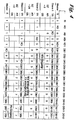
- FIG. 4 shows the tabular representation of the configuration cycle 1, based on the arrangement in FIG. 1.
- FIG. 5 shows the tabular representation of the configuration cycle 2, based on the arrangement in FIG. 1.
- the ring consists of a master and 3 subsystems slave 1 - slave 3.
- Each subsystem consists essentially of an optoelectric receiving device E and an electro optical transmission device S, from a telegram register TR, a working register AR, a data memory DS and a device BZ for setting the relative address.
- the subsystems without their own intelligence are limited to a fixed data length of a maximum of 4 bytes.
- the relative address BZ of the slave 1 subsystem is three bytes (16-24V outputs) and that of the subsystem 3 is two bytes (8-24V inputs).
- the slave 2 subsystem has its own intelligence and has a variable data length. In this case 24 bytes (16 analog inputs and 4 analog outputs).
- the participants, masters and subsystems slave 1 - slave 3 are arranged in a ring topology by means of optical fibers.
- the configuration, i.e. the ring participants are recorded and identified by the central control system master after initialization and ring synchronization.
- FIG. 2 shows the telegram of configuration cycle 1 that is used according to the invention in the exemplary arrangement according to FIG. 1.
- all subsystems slave 1 - slave 2 are in the "Wait” state and wait for instructions from the master. These instructions are sent in the configuration cycle and in the data cycle.
- the configuration cycle KZ1 starts from the "Listen Delimiter” state and the master sends "Idle signal" (log.1) at least 8 bit times.
- the slave 1 subsystem recognizes the start byte KD after idle signal 15, it begins with its configuration. If the entire ring is synchronized, all participants, master and slave 1-3 are in the "Listen Delimiter" state (waiting). The master sends the start byte KD, the address byte AB with the value "0", the frame check sum via the address byte AB corresponding to the address byte “repeat” ABr again "0", then the start byte KD1, followed by, during that Configuration cycle KZ1 definable 256 bytes.
- the first ring subscriber slave 1 is a subscriber with a fixed number of bytes BZ and is set to 3 bytes in terms of hardware.
- the address "0" received from the master stores slave 1, via its transfer register TR, in its working register AR, adds up its 3 bytes and transfers them to the address byte AB of the configuration tele by means of the transfer register TR grammes KT1 and sends the address 3 to the next subsystem slave 2.
- slave 1 forms the frame checksum of the address 3 and sends it via the transfer register TR to the subsystem slave 2 as address byte "repeat" ABr.
- slave 1 receives the next start byte KD1 and knows that the first three data bytes it receives are intended for it.
- Slave 1 reads the watchdog time in the first byte and overwrites the data byte DB1 with its identification identified in the data memory. In this case a 3 byte device with 8 ⁇ 24 V inputs. The data bytes DB2 and DB3 remain unused. All subsequent data bytes are only passed on when the frame checksum is created.
- the subsystem slave 2 has received the address "3" from slave 1 and writes this address in its working register AR.
- Slave 2 is an intelligent subsystem with variable data length, which can be assigned by the subsystem Slave 2 itself or by the master. This allows the ring to dynamically adapt optimally to its time-changing problem. 4 data bytes are permanently preselected for slave 2.
- the configuration cycle KZ1 ends with the last data byte DB256 received from the master and finally the frame check sum. At this point, all sub-systems slave 1-slave 3 are detected and identified.
- the master has created an image of the ring system. He knows the position and number of participants, their relative address and their identification.
- the slave 2 subsystem was determined by him as an intelligent subscriber, which has a variable data length and, for absolute addressing of all subscribers on the ring, forces a second configuration cycle KZ2.
- the configuration is complete when the data byte DB256 reaches the recipient of the master.
- the system is then again in the "Listen Delimiter" state.
- the master sends an idle signal (log. 1) and waits for n data cycles.
- the first data byte becomes the configuration byte.
- the configuration byte sent by the master can contain e.g. the setting and the watchdog timer and can be written into the data memory DS of the subsystems.
- the subsystem overwrites this configuration byte with its identity.
Landscapes
- Engineering & Computer Science (AREA)
- Computer Networks & Wireless Communication (AREA)
- Signal Processing (AREA)
- Small-Scale Networks (AREA)
Priority Applications (1)
| Application Number | Priority Date | Filing Date | Title |
|---|---|---|---|
| DE58908241T DE58908241D1 (de) | 1989-11-17 | 1989-11-17 | Verfahren zur Identifizierung von Busteilnehmern. |
Applications Claiming Priority (1)
| Application Number | Priority Date | Filing Date | Title |
|---|---|---|---|
| DE19883838152 DE3838152A1 (de) | 1988-11-10 | 1988-11-10 | Verfahren und identifizierung von busteilnehmern |
Publications (2)
| Publication Number | Publication Date |
|---|---|
| EP0428810A1 EP0428810A1 (de) | 1991-05-29 |
| EP0428810B1 true EP0428810B1 (de) | 1994-08-24 |
Family
ID=6366897
Family Applications (1)
| Application Number | Title | Priority Date | Filing Date |
|---|---|---|---|
| EP19890710079 Expired - Lifetime EP0428810B1 (de) | 1988-11-10 | 1989-11-17 | Verfahren zur Identifizierung von Busteilnehmern |
Country Status (2)
| Country | Link |
|---|---|
| EP (1) | EP0428810B1 (https=) |
| DE (1) | DE3838152A1 (https=) |
Cited By (1)
| Publication number | Priority date | Publication date | Assignee | Title |
|---|---|---|---|---|
| US11442736B2 (en) * | 2017-05-24 | 2022-09-13 | Wago Verwaltungsgesellschaft Mbh | Determination of data bus subscribers of a local bus |
Families Citing this family (11)
| Publication number | Priority date | Publication date | Assignee | Title |
|---|---|---|---|---|
| DE4020143A1 (de) * | 1990-06-25 | 1992-02-20 | Messer Griesheim Gmbh | Schweissstromquelle, insbesondere lichtbogen-schweissstromquelle, mit zusatzaggregaten |
| DE4124733C2 (de) * | 1991-07-25 | 1994-06-09 | Peters & Zabransky Ingenieurge | Datenübertragungssystem |
| ATE225585T1 (de) * | 1994-05-09 | 2002-10-15 | Europlex Res Ltd | Ringnetzsystem |
| DE4431206A1 (de) * | 1994-09-02 | 1996-03-07 | Sel Alcatel Ag | Verfahren zur Bestimmung einer Verbindungsidentifikation in einem Mehrrechnersystem und Mehrrechnersystem dafür |
| DE29907265U1 (de) | 1999-04-23 | 1999-09-16 | Siemens AG, 80333 München | Datenübertragungssystem mit selbsttätiger Konfigurierung |
| DE29908319U1 (de) * | 1999-05-10 | 2000-08-31 | Siemens AG, 80333 München | Netzwerk mit mehreren Teilnehmern sowie Teilnehmer für ein derartiges Netzwerk |
| DE19934514C5 (de) | 1999-07-22 | 2013-03-14 | Pilz Gmbh & Co. Kg | Verfahren zum Konfigurieren eines an einen Feldbus angeschlossenen Busteilnehmers |
| DE102004037227A1 (de) * | 2004-07-30 | 2006-02-16 | Sick Maihak Gmbh | Verfahren und Vorrichtung zur Adressierung von Teilnehmern eines Bussystems |
| DE102004041092A1 (de) * | 2004-08-24 | 2006-03-09 | Bosch Rexroth Aktiengesellschaft | Verfahren zum Zuweisen einer Geräteadresse an eine Nebenstation in einem Netzwerk sowie eine Nebenstation und eine Hauptstation für ein Netzwerk |
| DE102006013578B4 (de) * | 2006-03-22 | 2008-03-27 | Phoenix Contact Gmbh & Co. Kg | Verfahren und Steuer- und Datenübertragungsanlage zum Überprüfen des Einbauortes eines sicheren Kommunikationsteilnehmers |
| US8861337B2 (en) | 2012-05-07 | 2014-10-14 | Tesla Motors, Inc. | Robust communications in electrically noisy environments |
Family Cites Families (4)
| Publication number | Priority date | Publication date | Assignee | Title |
|---|---|---|---|---|
| DE3471219D1 (en) * | 1983-05-31 | 1988-06-16 | Oesterr Forsch Seibersdorf | Method and device for the transfer of data in a data loop |
| JPH0657008B2 (ja) * | 1985-04-24 | 1994-07-27 | 株式会社日立製作所 | マルチル−プ伝送系のシステム構造認識方式 |
| EP0290934B1 (de) * | 1987-05-14 | 1994-01-19 | Siemens Aktiengesellschaft | Verfahren zum Bilden einer Adressentabelle in einem ringförmigen Kommunikationsnetz |
| DE3806493A1 (de) * | 1988-03-01 | 1989-09-14 | Kloeckner Moeller Elektrizit | Bussystem |
-
1988
- 1988-11-10 DE DE19883838152 patent/DE3838152A1/de active Granted
-
1989
- 1989-11-17 EP EP19890710079 patent/EP0428810B1/de not_active Expired - Lifetime
Cited By (1)
| Publication number | Priority date | Publication date | Assignee | Title |
|---|---|---|---|---|
| US11442736B2 (en) * | 2017-05-24 | 2022-09-13 | Wago Verwaltungsgesellschaft Mbh | Determination of data bus subscribers of a local bus |
Also Published As
| Publication number | Publication date |
|---|---|
| DE3838152C2 (https=) | 1990-10-31 |
| DE3838152A1 (de) | 1990-05-31 |
| EP0428810A1 (de) | 1991-05-29 |
Similar Documents
| Publication | Publication Date | Title |
|---|---|---|
| DE3853347T2 (de) | Rundsendeübertragungssystem über ein Busnetzwerk. | |
| EP0428810B1 (de) | Verfahren zur Identifizierung von Busteilnehmern | |
| DE3924452C2 (de) | Verfahren zum Bestimmen der Adresse und der Anzahl von Knotenstationen in einem lokalen Netzwerk | |
| EP2090031B1 (de) | Verfahren und anordnung zur kommunikation auf einem lin-bus | |
| DE10328357A1 (de) | Netzwerkschnittstellen-Verwaltungssystem und Verfahren hierfür | |
| DE69937925T2 (de) | Verfahren und Vorrichtung zur Geräteidentifizierung in einem Kommunikationsnetz | |
| DE3736081A1 (de) | Verfahren und vorrichtung zur adresseneinstellung von an einen bus angeschlossenen teilnehmern | |
| DE19721740B4 (de) | Steuerungsverfahren für den Medienzugriff bei einem seriellen Bus | |
| EP0616286A1 (de) | Verfahren zur Vergabe von Bus-Adressen | |
| EP0725516B1 (de) | Verfahren zur Bestimmung der Position eines Netzteilnehmers in einem Netzwerk | |
| DE60131615T2 (de) | Topologiebestimmung in atm-netzen | |
| DE102015107865A1 (de) | Bussystem und Verfahren zum Zuteilen von Adressen von Busteilnehmern eines Bussystems | |
| DE4029290C2 (https=) | ||
| DE69323969T2 (de) | Verfahren zur Simulation der Übertragung über ein asynchrones Transfermodus-Übertragungsnetz und Simulator zur Übertragung über ein solches Netz | |
| DE69502686T2 (de) | Verfahren zur Einfügung von Zellen in einen ATM-Strom und Anlage zur Durchführung des Verfahrens | |
| WO2000004428A1 (de) | Verfahren und einrichtung zur konfiguration eines rechnergestützten systems | |
| DE4129412A1 (de) | Verfahren zur datenuebertragung und datenverarbeitungsanlage mit verteilten rechnerknoten | |
| EP1642207B1 (de) | Zuordnung von stationsadressen zu kommunikationsteilnehmern in einem bussystem | |
| DE10037969C2 (de) | Verfahren zur Erkennung einer flexiblen Vernetzung von Baugruppen bei beliebiger Netztopologie sowie zum Informationsaustausch zwischen solchen Baugruppen | |
| DE4433116B4 (de) | Verfahren zum selektiven Aufrufen von Netzelementen | |
| DE3739481C2 (https=) | ||
| EP0500987B1 (de) | Verfahren zum Erfassen von Kommunikationsendgeräteadressen in einer lokale Netze verbindenden Netzübergangseinrichtung | |
| EP0894381A1 (de) | Verfahren zur steuerung des zugriffs auf einen von mehreren datenquellen gemeinsam benutzten übertragungskanal | |
| DE3402577A1 (de) | Busanordnung zur datenuebertragung zwischen einer vielzahl von teilnehmern | |
| DE10310622B4 (de) | Verfahren und Datenübertragungsanlage zur bidirektionalen, synchronen Datenübertragung |
Legal Events
| Date | Code | Title | Description |
|---|---|---|---|
| PUAI | Public reference made under article 153(3) epc to a published international application that has entered the european phase |
Free format text: ORIGINAL CODE: 0009012 |
|
| AK | Designated contracting states |
Kind code of ref document: A1 Designated state(s): BE CH DE ES FR GB IT LI LU |
|
| RAP1 | Party data changed (applicant data changed or rights of an application transferred) |
Owner name: KLOECKNER-MOELLER GMBH |
|
| 17P | Request for examination filed |
Effective date: 19911031 |
|
| 17Q | First examination report despatched |
Effective date: 19940121 |
|
| GRAA | (expected) grant |
Free format text: ORIGINAL CODE: 0009210 |
|
| AK | Designated contracting states |
Kind code of ref document: B1 Designated state(s): BE CH DE ES FR GB IT LI LU |
|
| PG25 | Lapsed in a contracting state [announced via postgrant information from national office to epo] |
Ref country code: IT Free format text: LAPSE BECAUSE OF FAILURE TO SUBMIT A TRANSLATION OF THE DESCRIPTION OR TO PAY THE FEE WITHIN THE PRESCRIBED TIME-LIMIT;WARNING: LAPSES OF ITALIAN PATENTS WITH EFFECTIVE DATE BEFORE 2007 MAY HAVE OCCURRED AT ANY TIME BEFORE 2007. THE CORRECT EFFECTIVE DATE MAY BE DIFFERENT FROM THE ONE RECORDED. Effective date: 19940824 Ref country code: BE Effective date: 19940824 Ref country code: GB Effective date: 19940824 Ref country code: FR Effective date: 19940824 Ref country code: ES Free format text: THE PATENT HAS BEEN ANNULLED BY A DECISION OF A NATIONAL AUTHORITY Effective date: 19940824 |
|
| REF | Corresponds to: |
Ref document number: 58908241 Country of ref document: DE Date of ref document: 19940929 |
|
| PG25 | Lapsed in a contracting state [announced via postgrant information from national office to epo] |
Ref country code: CH Effective date: 19941130 Ref country code: LI Effective date: 19941130 Ref country code: LU Free format text: LAPSE BECAUSE OF NON-PAYMENT OF DUE FEES Effective date: 19941130 |
|
| EN | Fr: translation not filed | ||
| GBV | Gb: ep patent (uk) treated as always having been void in accordance with gb section 77(7)/1977 [no translation filed] |
Effective date: 19940824 |
|
| PGFP | Annual fee paid to national office [announced via postgrant information from national office to epo] |
Ref country code: DE Payment date: 19950317 Year of fee payment: 6 |
|
| PLBE | No opposition filed within time limit |
Free format text: ORIGINAL CODE: 0009261 |
|
| STAA | Information on the status of an ep patent application or granted ep patent |
Free format text: STATUS: NO OPPOSITION FILED WITHIN TIME LIMIT |
|
| REG | Reference to a national code |
Ref country code: CH Ref legal event code: PL |
|
| 26N | No opposition filed | ||
| PG25 | Lapsed in a contracting state [announced via postgrant information from national office to epo] |
Ref country code: DE Effective date: 19960801 |