EP0428472A2 - Asymmetrischer Reifen - Google Patents
Asymmetrischer Reifen Download PDFInfo
- Publication number
- EP0428472A2 EP0428472A2 EP90630189A EP90630189A EP0428472A2 EP 0428472 A2 EP0428472 A2 EP 0428472A2 EP 90630189 A EP90630189 A EP 90630189A EP 90630189 A EP90630189 A EP 90630189A EP 0428472 A2 EP0428472 A2 EP 0428472A2
- Authority
- EP
- European Patent Office
- Prior art keywords
- shoulder
- tire
- region
- tread portion
- net
- Prior art date
- Legal status (The legal status is an assumption and is not a legal conclusion. Google has not performed a legal analysis and makes no representation as to the accuracy of the status listed.)
- Granted
Links
Images


Classifications
-
- B—PERFORMING OPERATIONS; TRANSPORTING
- B60—VEHICLES IN GENERAL
- B60C—VEHICLE TYRES; TYRE INFLATION; TYRE CHANGING; CONNECTING VALVES TO INFLATABLE ELASTIC BODIES IN GENERAL; DEVICES OR ARRANGEMENTS RELATED TO TYRES
- B60C11/00—Tyre tread bands; Tread patterns; Anti-skid inserts
- B60C11/03—Tread patterns
- B60C11/13—Tread patterns characterised by the groove cross-section, e.g. for buttressing or preventing stone-trapping
- B60C11/1376—Three dimensional block surfaces departing from the enveloping tread contour
- B60C11/1384—Three dimensional block surfaces departing from the enveloping tread contour with chamfered block corners
-
- B—PERFORMING OPERATIONS; TRANSPORTING
- B60—VEHICLES IN GENERAL
- B60C—VEHICLE TYRES; TYRE INFLATION; TYRE CHANGING; CONNECTING VALVES TO INFLATABLE ELASTIC BODIES IN GENERAL; DEVICES OR ARRANGEMENTS RELATED TO TYRES
- B60C11/00—Tyre tread bands; Tread patterns; Anti-skid inserts
- B60C11/03—Tread patterns
- B60C11/0304—Asymmetric patterns
-
- B—PERFORMING OPERATIONS; TRANSPORTING
- B60—VEHICLES IN GENERAL
- B60C—VEHICLE TYRES; TYRE INFLATION; TYRE CHANGING; CONNECTING VALVES TO INFLATABLE ELASTIC BODIES IN GENERAL; DEVICES OR ARRANGEMENTS RELATED TO TYRES
- B60C11/00—Tyre tread bands; Tread patterns; Anti-skid inserts
- B60C11/03—Tread patterns
- B60C11/0306—Patterns comprising block rows or discontinuous ribs
-
- B—PERFORMING OPERATIONS; TRANSPORTING
- B60—VEHICLES IN GENERAL
- B60C—VEHICLE TYRES; TYRE INFLATION; TYRE CHANGING; CONNECTING VALVES TO INFLATABLE ELASTIC BODIES IN GENERAL; DEVICES OR ARRANGEMENTS RELATED TO TYRES
- B60C11/00—Tyre tread bands; Tread patterns; Anti-skid inserts
- B60C11/03—Tread patterns
- B60C11/0327—Tread patterns characterised by special properties of the tread pattern
- B60C11/033—Tread patterns characterised by special properties of the tread pattern by the void or net-to-gross ratios of the patterns
-
- B—PERFORMING OPERATIONS; TRANSPORTING
- B60—VEHICLES IN GENERAL
- B60C—VEHICLE TYRES; TYRE INFLATION; TYRE CHANGING; CONNECTING VALVES TO INFLATABLE ELASTIC BODIES IN GENERAL; DEVICES OR ARRANGEMENTS RELATED TO TYRES
- B60C11/00—Tyre tread bands; Tread patterns; Anti-skid inserts
- B60C11/14—Anti-skid inserts, e.g. vulcanised into the tread band
- B60C11/18—Anti-skid inserts, e.g. vulcanised into the tread band of strip form, e.g. metallic combs, rubber strips of different wear resistance
-
- B—PERFORMING OPERATIONS; TRANSPORTING
- B60—VEHICLES IN GENERAL
- B60C—VEHICLE TYRES; TYRE INFLATION; TYRE CHANGING; CONNECTING VALVES TO INFLATABLE ELASTIC BODIES IN GENERAL; DEVICES OR ARRANGEMENTS RELATED TO TYRES
- B60C11/00—Tyre tread bands; Tread patterns; Anti-skid inserts
- B60C11/03—Tread patterns
- B60C2011/0337—Tread patterns characterised by particular design features of the pattern
- B60C2011/0386—Continuous ribs
- B60C2011/0388—Continuous ribs provided at the equatorial plane
-
- B—PERFORMING OPERATIONS; TRANSPORTING
- B60—VEHICLES IN GENERAL
- B60C—VEHICLE TYRES; TYRE INFLATION; TYRE CHANGING; CONNECTING VALVES TO INFLATABLE ELASTIC BODIES IN GENERAL; DEVICES OR ARRANGEMENTS RELATED TO TYRES
- B60C11/00—Tyre tread bands; Tread patterns; Anti-skid inserts
- B60C11/03—Tread patterns
- B60C11/12—Tread patterns characterised by the use of narrow slits or incisions, e.g. sipes
- B60C11/1204—Tread patterns characterised by the use of narrow slits or incisions, e.g. sipes with special shape of the sipe
- B60C2011/1213—Tread patterns characterised by the use of narrow slits or incisions, e.g. sipes with special shape of the sipe sinusoidal or zigzag at the tread surface
-
- B—PERFORMING OPERATIONS; TRANSPORTING
- B60—VEHICLES IN GENERAL
- B60C—VEHICLE TYRES; TYRE INFLATION; TYRE CHANGING; CONNECTING VALVES TO INFLATABLE ELASTIC BODIES IN GENERAL; DEVICES OR ARRANGEMENTS RELATED TO TYRES
- B60C11/00—Tyre tread bands; Tread patterns; Anti-skid inserts
- B60C11/03—Tread patterns
- B60C11/12—Tread patterns characterised by the use of narrow slits or incisions, e.g. sipes
- B60C11/1236—Tread patterns characterised by the use of narrow slits or incisions, e.g. sipes with special arrangements in the tread pattern
- B60C2011/1254—Tread patterns characterised by the use of narrow slits or incisions, e.g. sipes with special arrangements in the tread pattern with closed sipe, i.e. not extending to a groove
Definitions
- the present invention relates generally to pneumatic tires and more specifically to a pneumatic tires which is asymmetrical with respect to its equatorial plane.
- a tire as a mechanical structure can be described in general terms as a nonrigid torus composed of a flexible carcass of high-tensile cords fastened to substantially inextensible annular beads that firmly anchor the tire to the rim.
- the internal inflation pressure stresses the tire in such a way that any external force causing deformation in the carcass results in a tire reaction force. For example, as greater load is applied to a tire the deflection and ground contact area increase until a portion of the tire sufficient to support the load is affected.
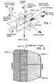
- the tire-axis system shown in Fig. 1 relates the forces acting on a tire by six quantities; three forces and three moments.
- the origin of this tire-axis system is the tire-road interface.
- Fig. 2 there is shown a schematic representation of a footprint of a tire mounted on the left front position of a vehicle, with the zones in which various functions of the tire are predominant indicated.
- Zone A of the footprint the predominant function is breaking deceleration, while in Zone B the predominant function is forward acceleration.
- Zone C the predominant function is cornering power while in Zone D the predominant function is steering precision when a vehicle is following a straight path. It can be observed from Fig. 2 that a tire functions differently not only laterally across the footprint, but also differently from front to rear of the footprint.
- Figs. 3A and 3B there are shown schematic representations of the footprints of prior art tires which are mounted on the left side of a pick-up truck which has an independent suspension system for each wheel.
- Fig. 3A represents a tire mounted in the left front position
- Fig. 3B represents a tire mounted in the left rear position.
- the tread pattern shown in Figs. 3A and 3B is symmetrical with respect to the equatorial plane of the tire.
- the footprint areas enclosed by lines Y and Y′ represent the tire footprints when an unloaded pick-up truck is parked.
- the footprint areas enclosed by lines Z and Z′ represent the tire footprints when the pickup truck is loaded at its rated capacity with the load balanced between the front and rear wheels.
- the footprint areas enclosed by lines X and X′ represent the tire footprints when the pickup truck is loaded at its rated capacity, but a majority of the load is upon the rear wheels. Large disparities in footprint sizes and shapes are also encountered during normal vehicle operation due to bouncing, cornering, rough roads, and so forth.
- the footprints of a tire will often be asymmetric with respect to its longitudinal axis even if the tread design of the tire itself is symmetrical with respect to the tire's equatorial plane.
- a tire having a symmetrical tread design will normally have a higher rate of treadwear on the outboard shoulder than the inboard shoulder.
- Figs. 4A and 4B there are shown schematic representations of the footprints of tires according to one of the preferred embodiments of the present invention mounted on the left side of a pick-up truck which has an independent suspension system for each wheel.
- Fig. 4A represents a tire mounted in the left front position
- Fig. 4B represents a tire mounted in the left rear position.
- tires according to the present invention have a tread pattern which is asymmetrical with respect to the equatorial plane of the tire.
- the footprint areas enclosed by lines Y and Y′ represent the tire footprints when an unloaded pick-up truck is parked.
- the footprint areas enclosed by lines Z and Z′ represent the tire footprints when the pick-up truck is loaded at its rated capacity with the load balanced between the front and rear wheels.
- the footprint areas enclosed by lines X and X′ represent the tire footprints when the pick-up truck is loaded at its rated capacity, but a majority of the load is upon the rear wheels. Large disparities in footprint sizes and shapes are also encountered during normal vehicle operations due to bouncing, cornering, rough roads, and so forth. It is clear from Figs. 3A and 3B that a tire according to the invention presents different ground contacting structures depending upon the operating conditions to which the tires are subjected.
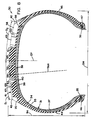
- Fig. 8 there is shown a cross-sectional view of a pneumatic tire 30 according to the present invention which has a carcass ply structure 31 reinforced by textile cords. It is understood that the structural features shown in Fig. 8 and described herein apply to each embodiment of the invention, including the most preferred embodiment.
- tire is understood to mean either a newly manufactured tire or a tire which has been retreaded.
- a "textile cord” is understood to mean either a monofilament structure or a multafilament structure.
- the carcass ply structure 31 comprises a sufficient number of plies of 33, 34 side-by-side cords to provide adequate load-bearing capacity in the tire in accordance with engineering standards which are well known in the tire art.
- the carcass ply cords are polyester, and the cords are oriented at 75° to 90° with respect to the equatorial plane EP of the tire.
- the "equatorial plane” is understood to mean a plane which is perpendicular to a tire's axis of rotation and passes through the center of its tread.
- a tire having a size of 245/70R15 has two carcass plies 33,34 reinforced of polyester cords having a construction of 1000/3, and the cords of the radially innermost carcass ply 33 are oriented at 90° with respect to the equatorial plane EP, while the cords of the radially outermost carcass ply 34 are oriented at about 90° with respect to the equatorial plane EP.
- Each ply 33, 34 of the carcass ply structure 31 has a pair of edge portions with each of the edge portions folded axially and radially outwardly about a substantially inextensible annular bead 35, 36.
- a tire according to the invention is of the tubeless variety having a substantially air impermeable liner 37 disposed between the carcass ply structure and the inside of the tire.
- a belt structure 38 reinforced by metallic cables is disposed radially outwardly of the carcass ply structure 31 and extends circumferentially thereabout.
- a "metallic cable” is understood to mean either a monofilament or multifilament structure.
- the belt structure comprises two belt plies 39, 40 each of which comprises side-by-side metallic cables having a structure of 2+2x.30 high tensile wire, and the cables of the radially innermost belt ply 39 are oriented at about 19° with respect to the equatorial plane EP while the cables of the radially outermost belt ply 40 are oriented at about 19° with respect to the equatorial plane EP.
- both the carcass ply structure 31 and the belt structure 38 are symmetrical with respect to the equatorial plane EP of the tire.
- a belt structure which is asymmetrical with respect to the equatorial plane, or have additional carcass ply structure components disposed in an asymmetrical manner with respect to the equatorial plane, in order to further reduce the differential in the rate of treadwear in opposed lateral portions of the tread of a tire.
- An elastomeric tread portion 41 comprising a suitable elastomeric compound is disposed radially outwardly of both the carcass ply structure 31 and the belt structure 38 and extends circumferentially thereabout.
- a radially outermost layer of the tread portion comprises a single elastomeric substance.
- the tread portion has first 42 and second 43 axially opposed shoulders, with a sidewall portion 44, extending radially inwardly from each shoulder to a bead portion 46, 47 of the tire.
- a tire according to the working example has a tread arc radius TAR, which is symmetrical with respect to the equatorial plane EP.
- tread arc radius is understood to mean a radius of curvature having its center on the equatorial plane which is followed by the radially outer surfaces of the tread portion.
- the tread has a tread arc radius which is symmetrical with respect to the equatorial plane of the tire.
- a tire according to the preferred embodiments which will be described hereafter in detail has an aspect ratio in the range of .60 to .85.
- Tires according to the working example have an aspect ratio of .70.
- aspect ratio is understood to mean the ratio of section height to maximum section width of a tire.
- Section height refers to the radially measured distance (SH) from the nominal bead diameter of a tire to the maximum outside diameter of the tire.
- Maximum section width refers to the greatest axial distance (SW) between the axially outer surfaces of a tire's sidewalls exclusive of indicia or ornamentation on the sidewalls.
- radial and radially are understood to refer to directions that are perpendicular to the axis of rotation of a tire
- lateral are understood to refer to directions going from one sidewall of a tire towards the other sidewall of the tire.
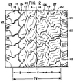
- Figs. 5-7 there is shown of the tread portion 41 of a tire according to one of the preferred embodiments.
- those features which are generic to all of the preferred embodiments, including the most preferred embodiment, will be set forth, as well as those features which apply to this specific preferred embodiment.
- the tread portion 41 of the tire has first and second axially opposed shoulders 42, 43.
- a tire according to the invention intended to be mounted with said first shoulder 42 inboard with respect to a vehicle at each of the wheel positions on the vehicle.
- the tread portion has at least two grooves 50, 51, 52, 53 therein which extend circumferentially about the tread. The circumferential grooves aid in the evacuation of water from the footprint and the lateral edges of the groove walls aid in lateral stability of the tire.
- the tread portion has first and second circumferential grooves 50, 51 disposed between the first shoulder 42 and the equatorial plane EP of the tire, and third and fourth circumferential grooves 52, 53 disposed between the equatorial plane EP and the second shoulder 43, with each said circumferential groove extending circumferentially about the tire.
- the axial width of each circumferential groove varies along the path of the groove to provide more edges for circumferential straight ahead traction and aids in reducing the noise generated by the tire.
- the tread portion 41 has a series of grooves 55, 56 therein which extend from the first shoulder 42 in a diagonal direction at least partially across the tread portion.
- the diagonal grooves provide traction and acceleration in a variety of operating conditions such as paved roads, mud and snow, and off-the-road. (See Fig. 2, zones A and B).
- the series of grooves 55, 56 extends diagonally across the tread portion from the first shoulder 42 to the second circumferential groove 51.
- one circumferentially extending groove 50 and the diagonally extending grooves 55, 56 cooperate to define a circumferentially extending array of block elements 57, 58 which is contiguous to the first shoulder 42.
- the block elements provide biting edges for traction.
- a first circumferentially extending array 60 of block elements 57, 58 is disposed between the first shoulder 42 and the first circumferential groove 50; a second circumferentially extending array 61 of block elements 62, 63 is disposed between the first and second circumferential grooves 50, 51; a first circumferentially extending rib 65 is disposed between the second and third circumferential grooves 51, 52; a second circumferentially extending rib 66 is disposed between the third and fourth circumferential grooves, 52, 53; and a third circumferentially extending rib 67 is disposed between the fourth circumferential groove 53 and the second shoulder 43.
- tread portion has three axial regions A, B, C each of which has an axial width equal to one-third of the tread width TW.
- tread width is understood to mean the greatest axial distance across the tread measured from the footprint of a tire when the tire is mounted on its specified rim, inflated to its specified inflation pressure and subjected to its rated load for said inflation pressure.
- the specified rim and inflation pressure can be determined from any of the following sources: (a) indicia molded onto a sidewall of a tire by the tire manufacturer; (b) specification or sales literature available from the tire manufacturer; (c) the YEARBOOK OF THE TIRE AND RIM ASSOCIATION for the year in which the tire was manufactured; (d) the YEARBOOK OF THE EUROPEAN TYRE AND RIM TECHNICAL ORGANIZATION for the year in which the tire was manufactured.
- the first region A of the tread portion is adjacent to the first shoulder 42.
- the second region B of the tread portion is adjacent to the second shoulder 43.
- the third region C of the tread portion is axially interposed between the first and second regions A, B.
- the tread portion has a net-to-gross ratio in said second region B which is at least 110% of the net-to-gross ratio of the first region A and the net-to-gross ratio of the third region C is less than the net-to-gross ratio of the second region B but not less than 90% of the net-to-gross ratio of the first region A.
- the net-to-gross ratio in the third region C is at least 90% of the net-to-gross ratio of the first region A but less than the net-to-gross ratio of the second region B.
- net-to-gross ratio of the third region C is greater than the net-to-gross ratio of the first region A but less than the net-to-gross ratio of the second region B.
- net to gross ratio is understood to mean the area of a tread that is actually in contact with the ground in a static footprint of a tire as a percentage of the total area of the footprint, or a region of a footprint, when the tire is mounted on its specified rim, inflated to its specified inflation pressure and subjected to its rated load at said inflation pressure. It is recognized in the tire art that the rate of treadwear will normally decrease as the net-to-gross ratio increases.
- the net-to-gross ratio in the first region A is 70%
- the net-to-gross ratio in the second region B is 77%
- the net-to-gross ratio in the third region C is 65%.
- the tread portion includes at least one structural feature which functions as a means for substantially equalizing the rate of treadwear in the first and second regions A, B of the tread portion.
- rate of treadwear in the first and second regions A, B of a tread portion is substantially equal if a tire which is mounted upon its specified rim and inflated to its specified inflation pressure and is not subjected to loads greater than its rated load, is used until it has no grooves remaining in either the first or second region of the tire, the depth of the grooves in the other said region is not greater than 10% of the depth of the same grooves when the tread is new.
- the tread portion has a means for substantially equalizing the rate of treadwear in the first and second regions A, B of the tread portion comprising at least one structural feature selected from the group consisting of: (a) chamfering the edges of block elements at a variety of angles in order to provide rigidity of varying degrees as the tread portion wears and also changes the net-to-gross ratio as the tread portion wears; (b) orienting the diagonally extending grooves at a variety of angles along the groove paths with respect to the equatorial plane of the tire so thereby imparting different rates of wear to different block elements which are bordered by a groove; (c) providing each said diagonally extending groove with a variety of widths along its path thereby affecting the net-to-gross ratio in a variety of locations thereby giving different rates of wear for different block elements bordered by the groove; (d) providing each said diagonally extending groove with a variety of depths along its path deeper grooves result in higher groove walls (block element walls) and faster wear rates
- the means for substantially equalizing the rate of treadwear in the first and second regions A, B of the tread portion includes the following structural features.
- the edges of the block elements 57, 58, 62, 63 in the arrays 60, 61 are chamfered at a variety of angles.
- the diagonally extending grooves 55, 56 which extend from the first shoulder are oriented at a variety of angles with respect to the equatorial plane EP of the tire.
- sipes are understood to mean very narrow grooves that do not remain open in the footprint of a tire. It is believed that at least one of these structural features, and preferably more than one of these features, should be employed in this embodiment.
- Tires according to the working example have tread portions wherein the radially outer part of the tread comprises a single elastomeric substance having a Shore A hardness of about 68.
- the first region of the tread portion may comprise an elastomer having a different Shore A hardness from the elastomer comprising the second region of the tread portion.
- Another structural feature which may be employed in the tread portion of a tire according to the invention relates to variations in the widths of the radially outermost surfaces of the block elements 57, 58 in the circumferentially extending array 60 of block elements which is contiguous to the first shoulder 42.
- the axially outermost extent of the radially outermost surface of each block element 57 of the first circumferentially extending array of block elements differs from that of the block elements 58 which are circumferentially next adjacent thereto.
- This feature is especially desirable if the tire will be used in off-the-road or muddy environments because it provides extra traction at the shoulder 42 and aids in expulsion of mud from a tire footprint.
- This feature results in the tread portion having a greater width D2 on one side of the equatorial plane EP than the width D1 on the other side of the equatorial plane.
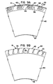
- the contour of the first shoulder 42 differs from the contour of the second shoulder 43 as viewed in a cross-section of the tire taken in a plane that contains the axis of rotation of the tire.
- This feature is best shown in Fig. 8.
- the first shoulder 42 has a contour that is conical and the second shoulder 43 has a contour that is arcuate.
- the arcuate contour which should be located on the outboard side with respect to a vehicle aids in vehicle handling because during turning or curving the footprint width and contact area on the outboard side of the tire increases due to load transfer.
- the inboard conical shoulder 42 further enhances biting grip and traction against less stable surfaces such as mud, snow and off-the-road surfaces.
- the first shoulder 42 has axially outermost surfaces which are conical and the second shoulder 43 has an axially outermost surface, or surfaces, which is/are arcuate. It is most preferred that the second shoulder 43 has a series of notches 70 therein such that the second shoulder has a multiplicity of axially outer surfaces, each of which has an arcuate contour. Structural details of the shoulders are shown in detail in Figs. 9A and 9B. The notches 70 in the second (arcuate) shoulder will provide some traction in snow and mud without reducing the stability of any rib contiguous with the second shoulder.
- a second embodiment of the invention wherein the tread portion of the tire has first, second and third circumferential grooves 76, 77, 78 therein which extend circumferentially about the tread portion.
- the first circumferential groove 76 is the nearest circumferential groove to the first shoulder 79 of the tire.
- the second circumferential groove 77 is the nearest circumferential groove to the second shoulder 80 of the tire.
- the third circumferential groove 78 is axially interposed between the other two circumferential grooves 76, 77.
- a first circumferentially continuous rib 81 is disposed between the second shoulder 80 of the tire and the nearest circumferential groove 72, which is referred to herein and in the claims as the second circumferential groove.
- a second circumferentially continuous rib 82 is disposed between the second and third circumferential grooves 77, 78.
- a series of diagonally extending grooves 83 in the tread portion originate at the first shoulder 79 and end in the second circumferentially extending rib 82, such that one circumferentially extending array 84 of block elements 85, 86 is disposed between the first and second circumferentially extending grooves 76, 78 and a second circumferentially extending array 87 of block elements 88, 89 is disposed between the first shoulder 79 and the nearest circumferential groove 76, which is referred to herein and in the claims as the first circumferential groove.
- the tread portion has a net-to-gross ratio in the second region B which is at least 120% of the net-to-gross ratio in the first region A and the net-to-gross ratio of the third region C is greater than the net-to-gross ratio of the first region A.
- the net-to-gross ratio in the first region A was 57%
- the net-to-gross ratio in the second region B was 71%
- the net-to-gross ratio in the third region C was 76%.
- the means for substantially equalizing the rate of treadwear in the first and second regions A, B of the tread portion includes the following structural features. At least some of the block elements 85, 86 in the first and second circumferentially extending arrays 84, 87 of block elements have edges that are chamfered at a variety of angles. The leading and trailing edges of the block elements 85, 86, 88, 89 of the first and second circumferentially extending arrays 84, 87 of block elements are oriented at a variety of angles with respect to the equatorial plane EP of the tire.
- the width of each of the diagonally extending grooves 83 varies along the path of the groove. It is believed that at least one of these structural features, and preferably more than one of these features, should be employed in this embodiment. Other structural features, such as a variety of shoulder contours, which have already been described may be employed in this embodiment also.
- a third embodiment of the invention wherein the tread portion 100 has a first circumferential groove 101 which follows a zig-zag path and extends circumferentially about the tread is disposed not more than 25% of the tread width TW away from the first shoulder 102.
- a second circumferential groove 103 which also follows a zig-zag path and extends circumferentially about the tread portion is disposed not more than 10% of the tread width TW away from the equatorial plane EP and is interposed between the equatorial plane and the second shoulder 104.
- a series of grooves 105 extends diagonally across the tread portion from the first shoulder 102 to the second circumferential groove 103.
- a circumferentially extending array 106 of pairs of laterally adjacent block elements 107, 108; 111, 112 is disposed between the first shoulder 102 and the second circumferential groove 103.
- a circumferentially extending rib 109 is disposed between the second circumferential groove 103 and the second shoulder 104.
- the tread portion has a net-to-gross ratio in the second region B which is at least 130% of the net-to-gross ratio in the first region A and the net-to-gross ratio of the third region C is greater than the net-to-gross ratio of the first region A but less than the net-to-gross ratio of the second region B.
- the net-to-gross ratio in the first region A was 64%
- the net-to-gross ratio in the second region B was 67%
- the net-to-gross ratio in the third region C was 88%.
- the means for substantially equalizing the rate of treadwear in the first and second regions A, B of the tread portion includes the following structural features.
- the diagonally extending grooves 105 follow curved paths such that the leading and trailing edges of the block elements 107, 108; 111, 112 are curved.
- the blocks 107, 108; 111, 112 in each pair of laterally next adjacent block elements each have an axial extent that differs from the axial extent of the other block element of the same pair.
- the axial extent of each block of the circumferentially extending array 106 of block elements differs from the axial extents of the blocks with are circumferentially next adjacent thereto.
- the circumferentially extending rib 109 is traversed by grooves 110, 113 which follow curved paths and have depths which are less than the depth of the second circumferential groove 103. It is believed that at least one of these structural features, and preferably more than one of these features, should be employed in this embodiment. Other structural features, such as a variety of shoulder contours, which have already been described may be employed in this embodiment also.
- a most preferred embodiment of the invention wherein the tread portion 115 has four circumferential grooves 116, 117, 118, 119 therein which extend circumferentially about the tread portion and follow zig-zag paths.
- zig-zag is understood to mean a line, path or groove comprising straight segments arranged end-to-end and oriented at angles of other than 0° with respect to one another.
- a series of diagonally extending grooves 120 in the tread portion extend from the first shoulder 121 to the second shoulder 122 and follow zig-zag paths.
- the circumferential grooves 116, 117, 118, 119 and diagonally extending grooves 120 and the shoulders 121, 122 cooperate to define five circumferentially extending arrays 123, 124, 125, 126, 127 of block elements, with the axial widths of said arrays all being different from one another.
- the tread portion has a net-to-gross ratio in the second region B which is at least 120% of the net-to-gross ratio in the first region A, and the net-to-gross of the third region C is greater than the net-to-gross ratio of the first region A but less than the net-to-gross ratio of the second region B.
- the net-to-gross ratio in the first region A was 57%
- net-to-gross ratio in the second region B was 72%
- the net-to-gross ratio in the third region was 77%.
- the means for substantially equalizing the rate of treadwear in the first and second regions A, B of the tread portion includes the following structural features. At least some of the block elements of some of said five circumferentially extending arrays 123, 124, 125, 126, 127 of block elements have edges which are chamfered at a variety of angles.
- the width of each diagonally extending groove 120 progressively decreases along the path of the groove from its greatest width at the first shoulder 121 to its least width at the second shoulder 172.
- the circumferential grooves 116, 117, 118, 119 have progressively narrower widths as a function of the axial distance of a circumferential groove from the first shoulder 121.
- each circumferentially extending array 123, 124, 125, 126, 127 of block elements is progressively less as a function of the axial distance of the array from the first shoulder 121.
- Next adjacent segments of the zig-zag path of each diagonally extending groove 120 have a variety of lengths.
- the depth of each diagonally extending groove 120 varies along the path of the groove. It is believed that at least one of these structural features, and preferably more than one of these features, should be employed in this most preferred embodiment. Other structural features, such as a variety of shoulder contours, which have already been described may be employed in this most preferred embodiment also.
Landscapes
- Engineering & Computer Science (AREA)
- Mechanical Engineering (AREA)
- Tires In General (AREA)
Applications Claiming Priority (2)
| Application Number | Priority Date | Filing Date | Title |
|---|---|---|---|
| US07/436,580 US5361814A (en) | 1989-11-15 | 1989-11-15 | Asymmetric tire |
| US436580 | 1989-11-15 |
Publications (3)
| Publication Number | Publication Date |
|---|---|
| EP0428472A2 true EP0428472A2 (de) | 1991-05-22 |
| EP0428472A3 EP0428472A3 (en) | 1991-11-13 |
| EP0428472B1 EP0428472B1 (de) | 1995-01-25 |
Family
ID=23732995
Family Applications (1)
| Application Number | Title | Priority Date | Filing Date |
|---|---|---|---|
| EP90630189A Expired - Lifetime EP0428472B1 (de) | 1989-11-15 | 1990-11-06 | Asymmetrischer Reifen |
Country Status (7)
| Country | Link |
|---|---|
| US (2) | US5361814A (de) |
| EP (1) | EP0428472B1 (de) |
| JP (1) | JPH0377702U (de) |
| AU (1) | AU630003B2 (de) |
| BR (1) | BR9005759A (de) |
| CA (1) | CA2018812C (de) |
| DE (1) | DE69016359T2 (de) |
Cited By (13)
| Publication number | Priority date | Publication date | Assignee | Title |
|---|---|---|---|---|
| EP0578216A1 (de) * | 1992-07-10 | 1994-01-12 | Michelin Recherche Et Technique S.A. | Asymetrische Reifenlauffläche |
| EP0625435A1 (de) * | 1993-05-20 | 1994-11-23 | Bridgestone Corporation | Luftreifen |
| EP0662397A1 (de) * | 1993-12-27 | 1995-07-12 | Sumitomo Rubber Industries Limited | Luftreifen |
| EP0661178A3 (de) * | 1993-12-28 | 1995-09-13 | Sumitomo Rubber Ind | Luftreifen und ihre Anordnung bei Fahrzeuge. |
| EP0681929A1 (de) * | 1994-04-15 | 1995-11-15 | The Goodyear Tire & Rubber Company | Radialer Luftreifen für PKW oder Lieferwagen |
| EP0686515A1 (de) * | 1994-06-10 | 1995-12-13 | Continental Aktiengesellschaft | Fahrzeugluftreifen mit asymmetrischer Lauffläche |
| FR2720979A1 (fr) * | 1994-06-14 | 1995-12-15 | Michelin & Cie | Bande de roulement pour pneumatique. |
| US5595619A (en) * | 1992-10-14 | 1997-01-21 | Sumitomo Rubber Industries, Ltd. | Pneumatic tire including shoulder parts |
| EP1106391A3 (de) * | 1999-12-06 | 2001-08-29 | Sumitomo Rubber Industries Ltd. | Luftreifen |
| EP1529659A2 (de) | 2003-11-04 | 2005-05-11 | Continental Aktiengesellschaft | Fahrzeugluftreifen |
| EP1798062A4 (de) * | 2004-09-13 | 2009-03-04 | Bridgestone Corp | Luftreifen |
| EP2529951A4 (de) * | 2010-01-25 | 2015-07-08 | Bridgestone Corp | Reifen |
| EP3663104A4 (de) * | 2017-08-02 | 2021-05-12 | The Yokohama Rubber Co., Ltd. | Luftreifen |
Families Citing this family (56)
| Publication number | Priority date | Publication date | Assignee | Title |
|---|---|---|---|---|
| AT402178B (de) * | 1994-02-25 | 1997-02-25 | Semperit Ag | Laufstreifen für einen fahrzeugluftreifen |
| CA2244198C (en) * | 1996-01-25 | 2006-05-09 | The Goodyear Tire & Rubber Company | An on/off road radial pneumatic light truck or automobile tire |
| US5924464A (en) * | 1996-03-29 | 1999-07-20 | Michelin Recherche Et Technique, S.A. | Tire having flow isolating grooves |
| WO1997046359A1 (en) * | 1996-06-06 | 1997-12-11 | Michelin Recherche Et Technique S.A. | Asymmetrical tire tread and method of making same |
| USD390819S (en) | 1996-12-27 | 1998-02-17 | Bridgestone/Firestone, Inc. | Tire tread |
| USD398887S (en) | 1997-07-02 | 1998-09-29 | The Goodyear Tire & Rubber Company | Tire tread |
| USD399175S (en) | 1997-07-11 | 1998-10-06 | The Goodyear Tire & Rubber Company | Tire tread |
| CA2297991A1 (en) * | 1997-09-17 | 1999-03-25 | Frederick William Miller | Footprints for nonrotatable automobile and light truck tires |
| US6408908B1 (en) | 1997-09-17 | 2002-06-25 | The Goodyear Tire & Rubber Company | Front tires and rear tires for automobile or light truck |
| US6443199B1 (en) | 1997-09-17 | 2002-09-03 | The Goodyear Tire & Rubber Company | Footprints for nonrotatable automobile and light truck tires |
| US6264453B1 (en) | 1997-10-27 | 2001-07-24 | The Goodyear Tire & Rubber Company | Article and method for composite tire mold blades |
| USD415985S (en) | 1998-01-23 | 1999-11-02 | The Goodyear Tire & Rubber Comapny | Tire tread |
| JP3310612B2 (ja) * | 1998-03-20 | 2002-08-05 | 住友ゴム工業株式会社 | 空気入りタイヤ |
| US6530405B1 (en) | 1998-08-26 | 2003-03-11 | The Goodyear Tire & Rubber Company | On/off-road tread |
| US6923232B1 (en) | 1999-06-24 | 2005-08-02 | The Goodyear Tire & Rubber Company | Tread for a light truck or automobile tire |
| USD424985S (en) * | 1999-06-24 | 2000-05-16 | The Goodyear Tire & Rubber Company | Tire tread |
| USD427950S (en) * | 1999-10-05 | 2000-07-11 | The Goodyear Tire & Rubber Company | Tire tread |
| US6609548B2 (en) * | 2000-05-11 | 2003-08-26 | Michelin Recherche Et Technique S.A. | Asymmetrical vehicle tire with balanced wet and dry performance |
| US7566102B2 (en) * | 2000-09-21 | 2009-07-28 | Innowheel Pty Ltd. | Multiple roller wheel |
| USD444740S1 (en) | 2000-11-20 | 2001-07-10 | The Goodyear Tire & Rubber Company | Tire tread |
| USD451441S1 (en) | 2000-12-04 | 2001-12-04 | The Goodyear Tire & Rubber Company | Tire tread |
| USD444109S1 (en) | 2001-02-20 | 2001-06-26 | The Goodyear Tire & Rubber Company | Tire tread |
| USD457128S1 (en) | 2001-02-20 | 2002-05-14 | The Goodyear Tire & Rubber Company | Tire tread |
| USD453919S1 (en) | 2001-04-05 | 2002-02-26 | The Goodyear Tire & Rubber Company | Tire tread |
| US6920906B2 (en) * | 2001-08-31 | 2005-07-26 | Bridgestone/Firestone North American Tire, Llc | Pneumatic tire with sidewall projections |
| KR20030047004A (ko) * | 2001-12-07 | 2003-06-18 | 금호산업주식회사 | 비대칭 트레드 패턴 공기입 타이어 |
| KR20030054130A (ko) * | 2001-12-24 | 2003-07-02 | 금호산업주식회사 | 비대칭 트레드 패턴을 갖는 비대칭 타이어 |
| KR20030059600A (ko) * | 2002-01-03 | 2003-07-10 | 금호산업주식회사 | 비대칭 트레드 패턴 타이어 |
| US6885931B2 (en) * | 2003-04-24 | 2005-04-26 | Visteon Global Technologies, Inc. | Control algorithm for a yaw stability management system |
| KR100784276B1 (ko) | 2003-07-09 | 2007-12-12 | 한국타이어 주식회사 | 스터드레스 스노우 타이어 |
| US7222651B2 (en) * | 2003-10-27 | 2007-05-29 | Treadfx, Llc | Tire for preventing rollover or oversteer of a vehicle |
| EP1637355B1 (de) * | 2004-09-17 | 2007-05-30 | Bridgestone Corporation | Luftreifen |
| JP4587795B2 (ja) * | 2004-12-01 | 2010-11-24 | 株式会社ブリヂストン | 空気入りタイヤ |
| US20060225975A1 (en) * | 2005-04-07 | 2006-10-12 | Raymond Pfaff | Drum brake pad |
| JP4348321B2 (ja) * | 2005-06-30 | 2009-10-21 | 住友ゴム工業株式会社 | 空気入りタイヤ |
| JP4954743B2 (ja) * | 2007-02-08 | 2012-06-20 | 東洋ゴム工業株式会社 | 空気入りタイヤ |
| US7784511B2 (en) * | 2007-03-02 | 2010-08-31 | The Goodyear Tire & Rubber Company | Pneumatic tire having extension blocks |
| JP4217266B1 (ja) * | 2007-08-07 | 2009-01-28 | 住友ゴム工業株式会社 | 空気入りタイヤ |
| ATE553935T1 (de) * | 2007-11-02 | 2012-05-15 | Bridgestone Corp | Radialluftreifen |
| DE102008029659A1 (de) | 2008-06-24 | 2009-12-31 | Continental Aktiengesellschaft | Fahrzeugluftreifen |
| US8556279B2 (en) * | 2008-12-08 | 2013-10-15 | Peter Rodney McKinnon | Handtruck |
| WO2011047443A1 (en) | 2009-10-23 | 2011-04-28 | Rotacaster Wheel Ltd | Wheel frame |
| US9278582B2 (en) | 2010-12-21 | 2016-03-08 | Bridgestone Americas Tire Operations, Llc | Tire tread having developing grooves |
| US9463670B2 (en) * | 2011-10-04 | 2016-10-11 | The Yokohama Rubber Co., Ltd. | Pneumatic tire |
| JP5387659B2 (ja) * | 2011-11-14 | 2014-01-15 | 横浜ゴム株式会社 | 空気入りタイヤ |
| JP5841558B2 (ja) * | 2013-04-23 | 2016-01-13 | 住友ゴム工業株式会社 | 空気入りタイヤ |
| DE16734858T1 (de) | 2015-01-06 | 2018-01-11 | Rotacaster Wheel Ltd. | Radrahmenkomponente |
| JP6445915B2 (ja) * | 2015-04-01 | 2018-12-26 | 株式会社ブリヂストン | タイヤ |
| EP3397512B1 (de) * | 2015-12-29 | 2020-02-05 | Pirelli Tyre S.p.A. | Reifen für fahrzeugräder |
| RU2019101961A (ru) | 2016-06-24 | 2020-07-24 | Коофи Инноватион Лимитед | Одноколесное самобалансирующееся транспортное средство с шиной, обеспечивающей движение карвингом |
| JP6899204B2 (ja) * | 2016-09-07 | 2021-07-07 | Toyo Tire株式会社 | 空気入りタイヤ |
| JP6912973B2 (ja) * | 2017-08-31 | 2021-08-04 | Toyo Tire株式会社 | 空気入りタイヤ |
| FI3738794T3 (fi) * | 2018-01-11 | 2023-12-14 | Yokohama Rubber Co Ltd | Nastoitettava rengas ja ilmarengas |
| JP7115043B2 (ja) * | 2018-05-31 | 2022-08-09 | 住友ゴム工業株式会社 | タイヤ |
| EP4008569B1 (de) * | 2020-12-01 | 2023-05-10 | Sumitomo Rubber Industries, Ltd. | Reifen |
| JP2023101288A (ja) * | 2022-01-07 | 2023-07-20 | 住友ゴム工業株式会社 | タイヤ |
Family Cites Families (42)
| Publication number | Priority date | Publication date | Assignee | Title |
|---|---|---|---|---|
| US2534869A (en) * | 1945-11-19 | 1950-12-19 | Bonnie G Jones | Motor vehicle tire |
| GB746479A (en) * | 1953-02-03 | 1956-03-14 | Dunlop Rubber Co | Improvements in pneumatic tyres |
| GB1019776A (en) * | 1961-12-18 | 1966-02-09 | Ciba Ltd | Basic ethers and process for preparing same |
| DE1167204B (de) * | 1962-01-13 | 1964-04-02 | Continental Gummi Werke Ag | Laufflaeche fuer Fahrzeugluftreifen |
| NL291515A (de) * | 1962-04-17 | |||
| NL134373C (de) * | 1965-07-24 | Michelin & Cie | ||
| US3847698A (en) * | 1969-05-05 | 1974-11-12 | Dunlop Ltd | Pneumatic tires |
| FR2080054A5 (de) * | 1970-02-20 | 1971-11-12 | Michelin & Cie | |
| BE790875A (fr) * | 1971-11-08 | 1973-05-03 | Michelin & Cie | Perfectionnements aux enveloppes de pneumatiques |
| DE2253717A1 (de) * | 1972-11-02 | 1974-05-09 | Uniroyal Ag | Fahrzeugluftreifen |
| DE2263455A1 (de) * | 1972-12-27 | 1974-07-04 | Barth Erich | Laufflaechenprofilierung fuer fahrzeugreifen |
| FR2236675B1 (de) * | 1973-07-03 | 1976-05-28 | Uniroyal | |
| IT1087461B (it) * | 1977-09-23 | 1985-06-04 | Pirelli | Perfezionamento a pneumatici per autovetture |
| JPS5470503A (en) * | 1977-11-17 | 1979-06-06 | Bridgestone Corp | Air-inflated tire for heavy load |
| USD261495S (en) | 1979-04-30 | 1981-10-27 | The Goodyear Tire & Rubber Company | Tire tread and buttress |
| JPS574409A (en) * | 1980-06-11 | 1982-01-11 | Bridgestone Corp | Pneumatic radial tire for heavy car with unsymmetrical tread pattern |
| USD269336S (en) | 1980-10-31 | 1983-06-14 | The Goodyear Tire & Rubber Company | Tire tread and buttress |
| DE3130574A1 (de) * | 1981-08-01 | 1983-02-17 | Bayer Ag, 5090 Leverkusen | Reifen mit asymmetrischem laufflaechenprofil |
| JPS59176104A (ja) * | 1983-03-25 | 1984-10-05 | Yokohama Rubber Co Ltd:The | 重荷重用空気入りラジアルタイヤ |
| JPS61184102A (ja) * | 1985-02-09 | 1986-08-16 | Bridgestone Corp | 非対称トレツドを具えた空気入りタイヤ |
| USD296093S (en) | 1985-04-30 | 1988-06-07 | Pirelli Coordinamento Pneumatici S.P.A. | Tire for vehicle wheels |
| IT1184525B (it) * | 1985-04-30 | 1987-10-28 | Pirelli | Pneumatico asimmetrico per ruote di veicoli |
| USD296680S (en) | 1985-09-23 | 1988-07-12 | The Uniroyal Goodrich Tire Company | Tire |
| US4690189A (en) * | 1986-01-29 | 1987-09-01 | The Goodyear Tire & Rubber Company | All-season pneumatic tire with chamfered tread blocks |
| US4732194A (en) * | 1986-04-17 | 1988-03-22 | The Yokohama Rubber Co., Ltd. | Asymmetric tire and tread |
| JPS6390404A (ja) * | 1986-10-03 | 1988-04-21 | Bridgestone Corp | 乗用車用空気入りラジアルタイヤの非対称パタ−ン |
| JP2639449B2 (ja) * | 1986-11-07 | 1997-08-13 | 株式会社 ブリヂストン | 空気入りラジアルタイヤ |
| JPS63159108A (ja) * | 1986-12-22 | 1988-07-02 | Yokohama Rubber Co Ltd:The | 空気入りタイヤ |
| US4758863A (en) * | 1987-02-17 | 1988-07-19 | Hewlett-Packard Company | Multi-image reticle |
| JPS6452507A (en) * | 1987-05-08 | 1989-02-28 | Bridgestone Corp | Pneumatic tire pair |
| JP2535349B2 (ja) * | 1987-06-09 | 1996-09-18 | 株式会社ブリヂストン | 空気入りタイヤ |
| JPS6467404A (en) * | 1987-09-07 | 1989-03-14 | Yokohama Rubber Co Ltd | Radial tire |
| USD307122S (en) | 1987-10-26 | 1990-04-10 | Michelin Recherche Et Technique | Tire |
| JPH01266001A (ja) * | 1988-04-19 | 1989-10-24 | Yokohama Rubber Co Ltd:The | 空気入りタイヤ |
| JPH07121645B2 (ja) * | 1988-08-31 | 1995-12-25 | 住友ゴム工業株式会社 | 空気入りタイヤ |
| USD325012S (en) | 1989-11-15 | 1992-03-31 | The Goodyear Tire & Rubber Company | Tire tread and buttress |
| USD321158S (en) | 1989-11-15 | 1991-10-29 | The Goodyear Tire & Rubber Company | Tire tread and buttress |
| USD325365S (en) | 1989-11-15 | 1992-04-14 | The Goodyear Tire & Rubber Company | Tire tread and buttress |
| USD326439S (en) | 1989-11-15 | 1992-05-26 | The Goodyear Tire & Rubber Company | Tire tread and buttress |
| USD326440S (en) | 1990-04-02 | 1992-05-26 | The Goodyear Tire & Rubber Company | Tire tread and buttress |
| USD326075S (en) | 1990-04-04 | 1992-05-12 | The Goodyear Tire & Rubber Company | Tire tread and buttress |
| USD324842S (en) | 1990-04-12 | 1992-03-24 | The Goodyear Tire & Rubber Company | Tire thread and buttress |
-
1989
- 1989-11-15 US US07/436,580 patent/US5361814A/en not_active Expired - Lifetime
-
1990
- 1990-06-12 CA CA002018812A patent/CA2018812C/en not_active Expired - Fee Related
- 1990-11-06 DE DE69016359T patent/DE69016359T2/de not_active Expired - Fee Related
- 1990-11-06 EP EP90630189A patent/EP0428472B1/de not_active Expired - Lifetime
- 1990-11-13 BR BR909005759A patent/BR9005759A/pt not_active IP Right Cessation
- 1990-11-14 JP JP1990118607U patent/JPH0377702U/ja active Pending
- 1990-11-14 AU AU66619/90A patent/AU630003B2/en not_active Ceased
-
1993
- 1993-10-21 US US08/140,337 patent/US5415215A/en not_active Expired - Lifetime
Cited By (20)
| Publication number | Priority date | Publication date | Assignee | Title |
|---|---|---|---|---|
| US5421387A (en) * | 1992-07-10 | 1995-06-06 | Michelin Recherche Et Technique S.A. | Asymmetrical tire tread |
| EP0578216A1 (de) * | 1992-07-10 | 1994-01-12 | Michelin Recherche Et Technique S.A. | Asymetrische Reifenlauffläche |
| US5595619A (en) * | 1992-10-14 | 1997-01-21 | Sumitomo Rubber Industries, Ltd. | Pneumatic tire including shoulder parts |
| EP0625435A1 (de) * | 1993-05-20 | 1994-11-23 | Bridgestone Corporation | Luftreifen |
| US5421391A (en) * | 1993-05-20 | 1995-06-06 | Bridgestone Corporation | Pneumatic tires |
| EP0662397A1 (de) * | 1993-12-27 | 1995-07-12 | Sumitomo Rubber Industries Limited | Luftreifen |
| EP0661178A3 (de) * | 1993-12-28 | 1995-09-13 | Sumitomo Rubber Ind | Luftreifen und ihre Anordnung bei Fahrzeuge. |
| EP0681929A1 (de) * | 1994-04-15 | 1995-11-15 | The Goodyear Tire & Rubber Company | Radialer Luftreifen für PKW oder Lieferwagen |
| US5658404A (en) * | 1994-04-15 | 1997-08-19 | The Goodyear Tire & Rubber Company | Radial pneumatic light truck or automobile tire |
| EP0686515A1 (de) * | 1994-06-10 | 1995-12-13 | Continental Aktiengesellschaft | Fahrzeugluftreifen mit asymmetrischer Lauffläche |
| FR2720979A1 (fr) * | 1994-06-14 | 1995-12-15 | Michelin & Cie | Bande de roulement pour pneumatique. |
| EP0687582A1 (de) * | 1994-06-14 | 1995-12-20 | COMPAGNIE GENERALE DES ETABLISSEMENTS MICHELIN-MICHELIN & CIE | Reifenlauffläche |
| US6595253B2 (en) | 1999-12-06 | 2003-07-22 | Sumitomo Rubber Industries, Ltd. | Pneumatic tire including circumferential groove having alternate constant width portions and widening portions |
| EP1106391A3 (de) * | 1999-12-06 | 2001-08-29 | Sumitomo Rubber Industries Ltd. | Luftreifen |
| EP1529659A2 (de) | 2003-11-04 | 2005-05-11 | Continental Aktiengesellschaft | Fahrzeugluftreifen |
| EP1529659A3 (de) * | 2003-11-04 | 2005-06-15 | Continental Aktiengesellschaft | Fahrzeugluftreifen |
| EP1798062A4 (de) * | 2004-09-13 | 2009-03-04 | Bridgestone Corp | Luftreifen |
| EP2529951A4 (de) * | 2010-01-25 | 2015-07-08 | Bridgestone Corp | Reifen |
| EP3663104A4 (de) * | 2017-08-02 | 2021-05-12 | The Yokohama Rubber Co., Ltd. | Luftreifen |
| US11613145B2 (en) | 2017-08-02 | 2023-03-28 | The Yokohama Rubber Co., Ltd. | Pneumatic tire |
Also Published As
| Publication number | Publication date |
|---|---|
| US5361814A (en) | 1994-11-08 |
| EP0428472A3 (en) | 1991-11-13 |
| JPH0377702U (de) | 1991-08-06 |
| US5415215A (en) | 1995-05-16 |
| DE69016359T2 (de) | 1995-09-07 |
| CA2018812A1 (en) | 1991-05-15 |
| AU630003B2 (en) | 1992-10-15 |
| AU6661990A (en) | 1991-05-23 |
| DE69016359D1 (de) | 1995-03-09 |
| BR9005759A (pt) | 1991-09-24 |
| CA2018812C (en) | 1999-02-02 |
| EP0428472B1 (de) | 1995-01-25 |
Similar Documents
| Publication | Publication Date | Title |
|---|---|---|
| US5361814A (en) | Asymmetric tire | |
| EP0318416B1 (de) | Luftreifen | |
| US4700762A (en) | Pneumatic tire therad with wide central groove and arcuate grooves | |
| EP1007377B1 (de) | Opferrippen für reifen mit verbesserten abnutzungseigenschaften | |
| EP0578216B1 (de) | Asymetrische Reifenlauffläche | |
| EP1923236B1 (de) | Luftreifen für Geländefahrten | |
| US5896905A (en) | Tread for heavy-vehicle tire in which the central ribs are provided with inclined incisions | |
| US5388625A (en) | Tire having tread with improved wear resistance | |
| EP0467146B1 (de) | Reifenlauffläche | |
| US4574857A (en) | Tractor tire tread | |
| CA1334374C (en) | Vehicle tire | |
| EP1127716B1 (de) | Ausgleich der Abnutzung von Spitzen und Fersen | |
| US5538060A (en) | Pneumatic tire having tread portion including blocks | |
| JPH04231201A (ja) | 空気入りタイヤ用トレッド | |
| EP0370699B1 (de) | Fahrzeugreifen | |
| EP1963111B1 (de) | Luftreifen mit asymmetrischem laufflächenprofil | |
| EP0778162B1 (de) | Luftreifen | |
| JP3467084B2 (ja) | 空気入りラジアルタイヤ | |
| EP4440853B1 (de) | Luftreifen für fahrzeugräder | |
| JP2024542529A (ja) | 車両ホイール用のタイヤ | |
| WO2026033358A1 (en) | Tyre for vehicle wheels |
Legal Events
| Date | Code | Title | Description |
|---|---|---|---|
| PUAI | Public reference made under article 153(3) epc to a published international application that has entered the european phase |
Free format text: ORIGINAL CODE: 0009012 |
|
| 17P | Request for examination filed |
Effective date: 19901115 |
|
| AK | Designated contracting states |
Kind code of ref document: A2 Designated state(s): BE DE FR GB NL |
|
| PUAL | Search report despatched |
Free format text: ORIGINAL CODE: 0009013 |
|
| AK | Designated contracting states |
Kind code of ref document: A3 Designated state(s): BE DE FR GB NL |
|
| 17Q | First examination report despatched |
Effective date: 19931206 |
|
| GRAA | (expected) grant |
Free format text: ORIGINAL CODE: 0009210 |
|
| AK | Designated contracting states |
Kind code of ref document: B1 Designated state(s): BE DE FR GB NL |
|
| REF | Corresponds to: |
Ref document number: 69016359 Country of ref document: DE Date of ref document: 19950309 |
|
| ET | Fr: translation filed | ||
| PLBE | No opposition filed within time limit |
Free format text: ORIGINAL CODE: 0009261 |
|
| STAA | Information on the status of an ep patent application or granted ep patent |
Free format text: STATUS: NO OPPOSITION FILED WITHIN TIME LIMIT |
|
| 26N | No opposition filed | ||
| PGFP | Annual fee paid to national office [announced via postgrant information from national office to epo] |
Ref country code: NL Payment date: 20000929 Year of fee payment: 11 |
|
| PGFP | Annual fee paid to national office [announced via postgrant information from national office to epo] |
Ref country code: GB Payment date: 20001004 Year of fee payment: 11 |
|
| PGFP | Annual fee paid to national office [announced via postgrant information from national office to epo] |
Ref country code: FR Payment date: 20001107 Year of fee payment: 11 |
|
| PGFP | Annual fee paid to national office [announced via postgrant information from national office to epo] |
Ref country code: DE Payment date: 20001124 Year of fee payment: 11 |
|
| PGFP | Annual fee paid to national office [announced via postgrant information from national office to epo] |
Ref country code: BE Payment date: 20001214 Year of fee payment: 11 |
|
| PG25 | Lapsed in a contracting state [announced via postgrant information from national office to epo] |
Ref country code: GB Free format text: LAPSE BECAUSE OF NON-PAYMENT OF DUE FEES Effective date: 20011106 |
|
| PG25 | Lapsed in a contracting state [announced via postgrant information from national office to epo] |
Ref country code: BE Free format text: LAPSE BECAUSE OF NON-PAYMENT OF DUE FEES Effective date: 20011130 |
|
| REG | Reference to a national code |
Ref country code: GB Ref legal event code: IF02 |
|
| BERE | Be: lapsed |
Owner name: THE GOODYEAR TIRE & RUBBER CY Effective date: 20011130 |
|
| PG25 | Lapsed in a contracting state [announced via postgrant information from national office to epo] |
Ref country code: NL Free format text: LAPSE BECAUSE OF NON-PAYMENT OF DUE FEES Effective date: 20020601 |
|
| GBPC | Gb: european patent ceased through non-payment of renewal fee |
Effective date: 20011106 |
|
| PG25 | Lapsed in a contracting state [announced via postgrant information from national office to epo] |
Ref country code: DE Free format text: LAPSE BECAUSE OF NON-PAYMENT OF DUE FEES Effective date: 20020702 |
|
| PG25 | Lapsed in a contracting state [announced via postgrant information from national office to epo] |
Ref country code: FR Free format text: LAPSE BECAUSE OF NON-PAYMENT OF DUE FEES Effective date: 20020730 |
|
| NLV4 | Nl: lapsed or anulled due to non-payment of the annual fee |
Effective date: 20020601 |
|
| REG | Reference to a national code |
Ref country code: FR Ref legal event code: ST |
|
| REG | Reference to a national code |
Ref country code: FR Ref legal event code: ST |