EP0427913B1 - Verfahren zur Anpassung der Endabregeldrehzahl des Reglers einer Einspritzpumpe einer ein Fahrzeug anreibenden luftverdichtenden Einspritzbrennkraftmaschine an die auf das Fahrzeug wirkenden Fahrwiderstände - Google Patents
Verfahren zur Anpassung der Endabregeldrehzahl des Reglers einer Einspritzpumpe einer ein Fahrzeug anreibenden luftverdichtenden Einspritzbrennkraftmaschine an die auf das Fahrzeug wirkenden Fahrwiderstände Download PDFInfo
- Publication number
- EP0427913B1 EP0427913B1 EP90112104A EP90112104A EP0427913B1 EP 0427913 B1 EP0427913 B1 EP 0427913B1 EP 90112104 A EP90112104 A EP 90112104A EP 90112104 A EP90112104 A EP 90112104A EP 0427913 B1 EP0427913 B1 EP 0427913B1
- Authority
- EP
- European Patent Office
- Prior art keywords
- vehicle
- ref
- speed
- combustion engine
- internal combustion
- Prior art date
- Legal status (The legal status is an assumption and is not a legal conclusion. Google has not performed a legal analysis and makes no representation as to the accuracy of the status listed.)
- Expired - Lifetime
Links
Images


Classifications
-
- F—MECHANICAL ENGINEERING; LIGHTING; HEATING; WEAPONS; BLASTING
- F02—COMBUSTION ENGINES; HOT-GAS OR COMBUSTION-PRODUCT ENGINE PLANTS
- F02D—CONTROLLING COMBUSTION ENGINES
- F02D31/00—Use of speed-sensing governors to control combustion engines, not otherwise provided for
- F02D31/001—Electric control of rotation speed
- F02D31/007—Electric control of rotation speed controlling fuel supply
- F02D31/009—Electric control of rotation speed controlling fuel supply for maximum speed control
Definitions
- the invention relates to a method for adapting the final control speed of the controller of an injection pump of an air-compressing injection internal combustion engine driving a vehicle to the driving resistances acting on the vehicle according to the preamble of the main claim.
- the invention is therefore based on the object of demonstrating a method of the type described in the preamble of the main claim, with which it is no longer necessary to adjust the final control speed to the currently selected gear ratio based on a specific driving resistance.
- a reference gear ratio is determined, which is also taken into account when determining the final deceleration speed dependent on the driving resistance.
- the final control speed can be determined independently of the gear ratio that has just been driven, in such a way that a sufficiently high connection speed is still present after each switching operation.
- the gear ratio is determined as the reference gear ratio, in which, in the event that the internal combustion engine is rotated up to its maximum permissible speed, there is still a connection speed in the next higher gear, assuming a common value for the duration of the gearshift operation, which is in the range of maximum torque of the internal combustion engine.
- the determination of the reference gear ratio is based on a reference driving resistance, which is determined on the one hand from the constant vehicle data, such as the vehicle front surface, drag coefficient, vehicle mass etc. and on the other hand from the reference data characterizing the expected driving conditions. These are, for example, the relative speed from the vehicle speed and the air speed, the rolling friction coefficient, and in particular the road gradient that mainly influences the driving resistance. In general, it can be said that the greater the driving resistance to be expected during driving (driving in rough terrain, larger road gradients, etc.), the lower the gear ratio or the higher the gear ratio at which the final control speed must be corresponds to the maximum permissible speed of the internal combustion engine.
- Claim 5 shows an advantageous development of the method according to the invention, with the aid of which the reference data can be re-entered in accordance with the anticipated use profile before each trip and thus taken into account.
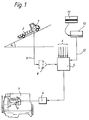
- FIG. 1 shows a diesel internal combustion engine driving a vehicle 2, on which a fuel injection pump 3 is arranged.
- the control rod of this injection pump 3 is actuated by an actuator 4, which in turn is controlled by an electronic control unit 5 becomes.
- the basic functions of the control unit 5 are the same as the electronic diesel controller (EDR) disclosed in MTZ 44 (1983) 10 pages 378-380 except for the difference that the control unit 5 additionally has a block for determining the final control speed according to the invention.
- 6 denotes those measuring lines which are also provided in the known electronic diesel controller.
- the control unit 5 is also supplied with a signal corresponding to the current road gradient ⁇ , which is detected via an inclination sensor 7 arranged on the vehicle 2.
- an integrating element 9 is provided in the measured value line 8 for smoothing the signal detected by the sensor 7.
- a reading device 10 for a mobile data carrier 11 (code card with magnetic stripe) is also attached to the vehicle 2 and is likewise connected to the electronic control unit 5 via the data line 12.
- the data for determining a reference driving resistance F W, ref are stored on this mobile data carrier 11 before the start of the journey.
- These reference data are firstly fixed vehicle data, such as the vehicle mass m, the moments of inertia of rotating components J R, drive , the front surface A of the vehicle 2, the drag coefficient c w etc., secondly, constant state variables such as the air density ⁇ 1, the acceleration due to gravity g etc and thirdly, the data which characterize the operational profile to be expected during driving. Specifically, these are the relative speed v rel, ref from the vehicle speed and the air speed for the determination of the reference air resistance, the rolling friction coefficient f ref for the determination of the reference rolling friction resistance and the road gradient angle ⁇ ref for the determination of the reference gradient resistance.
- this data (input block 14) taken from memory 13 first becomes reference driving resistance F W, ref , which is made up of the individual components reference air resistance F l, ref , reference rolling resistance F R, ref and reference pitch resistance F S, ref composed (see block 15, Fig. 2), according to the relationship calculated.
- the reference deceleration a v, ref acting on the vehicle 2 is then made in block 16 from this reference driving resistance F W, ref , taking into account the vehicle mass m, the individual moments of inertia J R, drive and the dynamic tire radius r dyn determined.
- this reference delay a v, ref and an assumed switching time t s between two gear ratios exactly that gear ratio, referred to as reference gear ratio i G, ref , is calculated in block 17, from which, after the internal combustion engine 1 has been turned out, up to the maximum permissible rotational speed of the Internal combustion engine n max in the next higher gear ratio a given connection speed n target is given.
- This connection speed n target lies in the range of the maximum torque of the internal combustion engine 1.
- i G ref is determined according to the regulation
- a gearbox with a geometric gradation is provided, the quantity ⁇ representing the corresponding increment.
- i D denotes the value for the constant rear axle ratio. Since the calculated value for i G, ref in most cases does not exactly correspond to a real gear ratio, the real gear ratio closest to the calculated value can be read out in block 18 as a reference gear ratio i ref . However, this adjustment is not necessary for the function, ie it can also be calculated with a reference translation i ref that is not actually available.
- a relatively large reference ratio i ref is required, i.e., even in a relatively low gear step, after the internal combustion engine 1 has been turned out up to its maximum speed n max, there must be a speed in the next higher gear step , which is in the range of the maximum torque of the internal combustion engine. If the driving resistance to be expected is relatively low, a higher gear ratio, ie a lower gear ratio, is sufficient as the reference gear ratio i ref .
- connection speed is then of course below the speed at which the torque is maximum, however, it is still in a range in which the vehicle 2 can continue to accelerate under the underlying driving conditions.
- the reference data v rel, ref , f ref and ⁇ ref that characterize the operating conditions. If, for example, it is to be expected that the vehicle will have to negotiate larger inclines when the vehicle is in operation, that is to say that the mean incline angle is relatively large, the corresponding reference inclination angle ⁇ ref should be chosen to be relatively small.
- a small reference pitch angle ⁇ ref leads to a relatively low reference driving resistance F W, ref (block 15) and consequently to a small reference deceleration amount a v, ref (block 16).
- F W, ref relatively low reference driving resistance
- a v, ref With a low reference deceleration a v, ref , however, there is a high reference gear ratio i G, ref (block 17), i.e. a relatively low gear stage (block 18), from which, after revving up to the maximum permissible speed n max, in the next higher gear a connection speed in the range of the maximum torque is given.
- FIG. 3 shows how the electronic control unit 5 uses this previously calculated reference ratio i ref to determine the current final control speed n ab as a function of the current gradient resistance, which mainly influences the driving resistance.
- the signal ⁇ (slope angle) corresponding to the current road gradient and detected by the sensor 7 is now read in via the input block 19. From one to one The characteristic value stored in the read-only memory is now read out in block 20 the deceleration a v corresponding to this current road gradient ⁇ which acts on the vehicle 2 during a switching operation. In the subsequent block 21, the calculation of the current final control speed n ab takes place , among other things, with the previously determined current deceleration a v and with the reference gear ratio i ref determined after the start of the internal combustion engine in accordance with the regulation .
- n target denotes the desired connection speed in the area of the maximum torque of the internal combustion engine
- ⁇ the step change of the geometrically graded gearbox
- t the specified shift duration
- i D the rear axle gear ratio
- r dyn the dynamic tire radius
- the final control speed n ab is set in block 23 to the maximum permissible speed n max in order to rule out damage to the internal combustion engine 1 due to excessive speeds. If the calculated value of n from below of n max, in decision block 24 is followed by query whether the calculated Endabregelfitiere n from below a predetermined minimum speed n min. In this case, the final control speed n ab is set to n min in block 25. This check is provided in the event that, due to a technical defect in the electronic control unit 5, an excessively low final control speed n ab is determined and a sufficient connection speed could therefore no longer be ensured after a switching operation. Furthermore, the limitation to n min takes account of the user-friendliness by always having a certain speed range and thus also a certain minimum engine power available.
- n ab is used as the basis for the control of the control rod of the fuel injection pump 3.
- the driver is shown the current final control speed n ab on a display (output block 26).
- a query is made as to whether the internal combustion engine has already been switched off. If not, The control branches back to point 28, after which the current road gradient is read again. If the internal combustion engine is switched off, new reference values can be entered into the memory 13 before starting again (reading of the mobile data carrier 11 by means of the reading device 10). If this does not take place before the start of the internal combustion engine 1, the reference data used are those which are still saved from an earlier read-in process.
Landscapes
- Engineering & Computer Science (AREA)
- Chemical & Material Sciences (AREA)
- Combustion & Propulsion (AREA)
- Mechanical Engineering (AREA)
- General Engineering & Computer Science (AREA)
- Control Of Transmission Device (AREA)
- Control Of Vehicle Engines Or Engines For Specific Uses (AREA)
- Electrical Control Of Air Or Fuel Supplied To Internal-Combustion Engine (AREA)
- Combined Controls Of Internal Combustion Engines (AREA)
- High-Pressure Fuel Injection Pump Control (AREA)
Priority Applications (1)
| Application Number | Priority Date | Filing Date | Title |
|---|---|---|---|
| AT90112104T ATE101898T1 (de) | 1989-09-20 | 1990-06-26 | Verfahren zur anpassung der endabregeldrehzahl des reglers einer einspritzpumpe einer ein fahrzeug anreibenden luftverdichtenden einspritzbrennkraftmaschine an die auf das fahrzeug wirkenden fahrwiderstaende. |
Applications Claiming Priority (2)
| Application Number | Priority Date | Filing Date | Title |
|---|---|---|---|
| DE3931327A DE3931327C1 (enExample) | 1989-09-20 | 1989-09-20 | |
| DE3931327 | 1989-09-20 |
Publications (3)
| Publication Number | Publication Date |
|---|---|
| EP0427913A2 EP0427913A2 (de) | 1991-05-22 |
| EP0427913A3 EP0427913A3 (en) | 1992-12-02 |
| EP0427913B1 true EP0427913B1 (de) | 1994-02-23 |
Family
ID=6389777
Family Applications (1)
| Application Number | Title | Priority Date | Filing Date |
|---|---|---|---|
| EP90112104A Expired - Lifetime EP0427913B1 (de) | 1989-09-20 | 1990-06-26 | Verfahren zur Anpassung der Endabregeldrehzahl des Reglers einer Einspritzpumpe einer ein Fahrzeug anreibenden luftverdichtenden Einspritzbrennkraftmaschine an die auf das Fahrzeug wirkenden Fahrwiderstände |
Country Status (3)
| Country | Link |
|---|---|
| EP (1) | EP0427913B1 (enExample) |
| AT (1) | ATE101898T1 (enExample) |
| DE (1) | DE3931327C1 (enExample) |
Cited By (1)
| Publication number | Priority date | Publication date | Assignee | Title |
|---|---|---|---|---|
| US5465208A (en) * | 1992-05-13 | 1995-11-07 | Honda Giken Kogyo Kabushiki Kaisha | Power source output control system of vehicle with travel resistance detector |
Families Citing this family (1)
| Publication number | Priority date | Publication date | Assignee | Title |
|---|---|---|---|---|
| DE10144699B4 (de) * | 2000-09-16 | 2014-06-12 | Volkswagen Ag | Verfahren zur Bestimmung der aktuellen Fahrzeugmasse |
Family Cites Families (3)
| Publication number | Priority date | Publication date | Assignee | Title |
|---|---|---|---|---|
| JPS6217328A (ja) * | 1985-07-15 | 1987-01-26 | Diesel Kiki Co Ltd | 内燃機関車輛用制御装置 |
| DE3613685C1 (de) * | 1986-04-23 | 1987-03-12 | Daimler Benz Ag | Vorrichtung zur gammanderung der Endabregelkennlinie des Reglers einer Einspritzpumpe einer ein Fahrzeug antreibenden Dieselbrennkraftmaschine |
| DE3813390A1 (de) * | 1988-04-21 | 1989-11-02 | Daimler Benz Ag | Verfahren zur steuerung der kraftstoffzufuhr bei einer ein fahrzeug antreibenden brennkraftmaschine |
-
1989
- 1989-09-20 DE DE3931327A patent/DE3931327C1/de not_active Expired - Lifetime
-
1990
- 1990-06-26 AT AT90112104T patent/ATE101898T1/de not_active IP Right Cessation
- 1990-06-26 EP EP90112104A patent/EP0427913B1/de not_active Expired - Lifetime
Non-Patent Citations (1)
| Title |
|---|
| Proc. of Int. Congress on Transportation Electronics, Okt. 17-18, 1988, Dearborn; S. 277-294; "Cummins Electronic Controls ..." * |
Cited By (1)
| Publication number | Priority date | Publication date | Assignee | Title |
|---|---|---|---|---|
| US5465208A (en) * | 1992-05-13 | 1995-11-07 | Honda Giken Kogyo Kabushiki Kaisha | Power source output control system of vehicle with travel resistance detector |
Also Published As
| Publication number | Publication date |
|---|---|
| EP0427913A3 (en) | 1992-12-02 |
| EP0427913A2 (de) | 1991-05-22 |
| DE3931327C1 (enExample) | 1990-08-09 |
| ATE101898T1 (de) | 1994-03-15 |
Similar Documents
| Publication | Publication Date | Title |
|---|---|---|
| EP0156820B1 (de) | Verfahren und schaltungsvorrichtung zur ermittlung des verbrauchsoptimalen getriebeganges eines kraftfahrzeugantriebes | |
| DE60224073T2 (de) | Kraftfahrzeug mit automatisiertem getriebe | |
| DE3539682C2 (enExample) | ||
| DE60216491T2 (de) | Geschwindigkeitsregelung für Fahrzeuge | |
| DE4306086C2 (de) | Vorrichtung und Verfahren zur Steuerung eines Motors | |
| DE19754461B4 (de) | Kraftübertragungssteuerung für ein Automobil | |
| EP0278232B1 (de) | Verfahren zur Beeinflussung der Fahrgeschwindigkeit eines Kraftfahrzeugs und Einrichtung zur Durchführung des Verfahrens | |
| DE102010007756B4 (de) | Verfahren zum Steuern eines Fahrzeugmotors während Hochleistungsfahrereignissen | |
| WO2000025046A1 (de) | Verfahren zur steuerung eines automatgetriebes eines kraftfahrzeuges bei einer spontanen gas-pedalrücknahme | |
| WO2007099033A1 (de) | Verfahren zur steuerung eines automatgetriebes und getriebesteuereinrichtung mit verbrauchskennfeld-ermittlungsvorrichtung | |
| WO2000031442A1 (de) | Verfahren zur steuerung eines schaltvorganges in automatikgetrieben | |
| DE602004007805T2 (de) | Verfahren zur optimierung einer bremssequenz | |
| DE3721605A1 (de) | Steuerungssystem fuer verbrennungsmotoren | |
| DE60316549T2 (de) | Vorrichtung zur Bestimmung des Kraftstoffverbrauches eines Fahrzeuges | |
| DE3443038A1 (de) | Verfahren und vorrichtung zur steuerung des betriebs eines drosselventils | |
| DE2712327A1 (de) | Verfahren zur selbsttaetigen regelung von kraftfahrzeugen | |
| EP0892725B1 (de) | Einrichtung für den ökonomischen betrieb von kraftfahrzeugen | |
| DE60206071T2 (de) | Fahrzeug und verfahren zur automatischen gangwahl in einem in einem fahrzeug angebrachten getriebe | |
| DE2336772A1 (de) | Einrichtung zur automatischen schaltung von kraftfahrzeuggetrieben | |
| DE60224573T2 (de) | Antriebseinheit für kraftfahrzeug | |
| DE2942961A1 (de) | Verfahren zum optimieren des kraftstoffverbrauches | |
| DE102016102622A1 (de) | Verfahren zum Reduzieren der von einem Motor eines Kraftfahrzeugs verbrauchten Kraftstoffmenge | |
| EP0427913B1 (de) | Verfahren zur Anpassung der Endabregeldrehzahl des Reglers einer Einspritzpumpe einer ein Fahrzeug anreibenden luftverdichtenden Einspritzbrennkraftmaschine an die auf das Fahrzeug wirkenden Fahrwiderstände | |
| DE4223253C2 (de) | Steuereinrichtung für ein Fahrzeug | |
| DE10084468B4 (de) | Verfahren und Anordnung zum Steuern eines automatischen Schaltgetriebes |
Legal Events
| Date | Code | Title | Description |
|---|---|---|---|
| PUAI | Public reference made under article 153(3) epc to a published international application that has entered the european phase |
Free format text: ORIGINAL CODE: 0009012 |
|
| AK | Designated contracting states |
Kind code of ref document: A2 Designated state(s): AT CH FR GB IT LI |
|
| PUAL | Search report despatched |
Free format text: ORIGINAL CODE: 0009013 |
|
| AK | Designated contracting states |
Kind code of ref document: A3 Designated state(s): AT CH FR GB IT LI |
|
| 17P | Request for examination filed |
Effective date: 19921023 |
|
| 17Q | First examination report despatched |
Effective date: 19930203 |
|
| ITF | It: translation for a ep patent filed | ||
| GRAA | (expected) grant |
Free format text: ORIGINAL CODE: 0009210 |
|
| AK | Designated contracting states |
Kind code of ref document: B1 Designated state(s): AT CH FR GB IT LI |
|
| REF | Corresponds to: |
Ref document number: 101898 Country of ref document: AT Date of ref document: 19940315 Kind code of ref document: T |
|
| GBT | Gb: translation of ep patent filed (gb section 77(6)(a)/1977) |
Effective date: 19940407 |
|
| ET | Fr: translation filed | ||
| PLBE | No opposition filed within time limit |
Free format text: ORIGINAL CODE: 0009261 |
|
| STAA | Information on the status of an ep patent application or granted ep patent |
Free format text: STATUS: NO OPPOSITION FILED WITHIN TIME LIMIT |
|
| 26N | No opposition filed | ||
| ITTA | It: last paid annual fee | ||
| PGFP | Annual fee paid to national office [announced via postgrant information from national office to epo] |
Ref country code: FR Payment date: 19960614 Year of fee payment: 7 |
|
| PGFP | Annual fee paid to national office [announced via postgrant information from national office to epo] |
Ref country code: AT Payment date: 19960619 Year of fee payment: 7 |
|
| PGFP | Annual fee paid to national office [announced via postgrant information from national office to epo] |
Ref country code: GB Payment date: 19960620 Year of fee payment: 7 |
|
| PGFP | Annual fee paid to national office [announced via postgrant information from national office to epo] |
Ref country code: CH Payment date: 19960621 Year of fee payment: 7 |
|
| PG25 | Lapsed in a contracting state [announced via postgrant information from national office to epo] |
Ref country code: GB Free format text: LAPSE BECAUSE OF NON-PAYMENT OF DUE FEES Effective date: 19970626 Ref country code: AT Effective date: 19970626 |
|
| PG25 | Lapsed in a contracting state [announced via postgrant information from national office to epo] |
Ref country code: LI Free format text: LAPSE BECAUSE OF NON-PAYMENT OF DUE FEES Effective date: 19970630 Ref country code: CH Free format text: LAPSE BECAUSE OF NON-PAYMENT OF DUE FEES Effective date: 19970630 |
|
| REG | Reference to a national code |
Ref country code: CH Ref legal event code: PFA Free format text: MERCEDES-BENZ AKTIENGESELLSCHAFT TRANSFER- DAIMLER-BENZ AKTIENGESELLSCHAFT |
|
| REG | Reference to a national code |
Ref country code: CH Ref legal event code: PL |
|
| GBPC | Gb: european patent ceased through non-payment of renewal fee |
Effective date: 19970626 |
|
| PG25 | Lapsed in a contracting state [announced via postgrant information from national office to epo] |
Ref country code: FR Free format text: LAPSE BECAUSE OF NON-PAYMENT OF DUE FEES Effective date: 19980227 |
|
| REG | Reference to a national code |
Ref country code: FR Ref legal event code: TP |
|
| REG | Reference to a national code |
Ref country code: FR Ref legal event code: ST |
|
| REG | Reference to a national code |
Ref country code: FR Ref legal event code: ST |
|
| PG25 | Lapsed in a contracting state [announced via postgrant information from national office to epo] |
Ref country code: IT Free format text: LAPSE BECAUSE OF NON-PAYMENT OF DUE FEES;WARNING: LAPSES OF ITALIAN PATENTS WITH EFFECTIVE DATE BEFORE 2007 MAY HAVE OCCURRED AT ANY TIME BEFORE 2007. THE CORRECT EFFECTIVE DATE MAY BE DIFFERENT FROM THE ONE RECORDED. Effective date: 20050626 |