EP0426869B1 - Process for manufacturing unidirectional silicon steel sheet excellent in magnetic properties - Google Patents

Process for manufacturing unidirectional silicon steel sheet excellent in magnetic properties Download PDF

Info

Publication number
EP0426869B1
EP0426869B1 EP90907406A EP90907406A EP0426869B1 EP 0426869 B1 EP0426869 B1 EP 0426869B1 EP 90907406 A EP90907406 A EP 90907406A EP 90907406 A EP90907406 A EP 90907406A EP 0426869 B1 EP0426869 B1 EP 0426869B1
Authority
EP
European Patent Office
Prior art keywords
temperature
rolling
steel sheet
sheet
annealing
Prior art date
Legal status (The legal status is an assumption and is not a legal conclusion. Google has not performed a legal analysis and makes no representation as to the accuracy of the status listed.)
Expired - Lifetime
Application number
EP90907406A
Other languages
German (de)
French (fr)
Other versions
EP0426869A4 (en
EP0426869A1 (en
Inventor
Toshito Kawasaki Steel Corp. Takamiya
Masahiko Kawasaki Steel Corporation Manabe
Fumihiko Kawasaki Steel Corporation Takeuchi
Takashi Kawasaki Steel Corporation Obara
Yoshiaki Kawasaki Steel Corp. Hanshin Works Iida
Current Assignee (The listed assignees may be inaccurate. Google has not performed a legal analysis and makes no representation or warranty as to the accuracy of the list.)
JFE Steel Corp
Original Assignee
Kawasaki Steel Corp
Priority date (The priority date is an assumption and is not a legal conclusion. Google has not performed a legal analysis and makes no representation as to the accuracy of the date listed.)
Filing date
Publication date
Priority claimed from JP11364389A external-priority patent/JPH0310020A/en
Application filed by Kawasaki Steel Corp filed Critical Kawasaki Steel Corp
Publication of EP0426869A1 publication Critical patent/EP0426869A1/en
Publication of EP0426869A4 publication Critical patent/EP0426869A4/xx
Application granted granted Critical
Publication of EP0426869B1 publication Critical patent/EP0426869B1/en
Anticipated expiration legal-status Critical
Expired - Lifetime legal-status Critical Current

Links

Images

Classifications

    • C—CHEMISTRY; METALLURGY
    • C21—METALLURGY OF IRON
    • C21D—MODIFYING THE PHYSICAL STRUCTURE OF FERROUS METALS; GENERAL DEVICES FOR HEAT TREATMENT OF FERROUS OR NON-FERROUS METALS OR ALLOYS; MAKING METAL MALLEABLE, e.g. BY DECARBURISATION OR TEMPERING
    • C21D8/00—Modifying the physical properties of ferrous metals or ferrous alloys by deformation combined with, or followed by, heat treatment
    • C21D8/12—Modifying the physical properties of ferrous metals or ferrous alloys by deformation combined with, or followed by, heat treatment during manufacturing of articles with special electromagnetic properties
    • C—CHEMISTRY; METALLURGY
    • C21—METALLURGY OF IRON
    • C21D—MODIFYING THE PHYSICAL STRUCTURE OF FERROUS METALS; GENERAL DEVICES FOR HEAT TREATMENT OF FERROUS OR NON-FERROUS METALS OR ALLOYS; MAKING METAL MALLEABLE, e.g. BY DECARBURISATION OR TEMPERING
    • C21D8/00—Modifying the physical properties of ferrous metals or ferrous alloys by deformation combined with, or followed by, heat treatment
    • C21D8/12—Modifying the physical properties of ferrous metals or ferrous alloys by deformation combined with, or followed by, heat treatment during manufacturing of articles with special electromagnetic properties
    • C21D8/1216—Modifying the physical properties of ferrous metals or ferrous alloys by deformation combined with, or followed by, heat treatment during manufacturing of articles with special electromagnetic properties characterised by the working steps
    • C21D8/1222—Hot rolling

Definitions

  • This invention relates to a method of producing grain oriented silicon steel sheets having improved magnetic properties.
  • grain oriented silicon steel sheets are mainly used as the material for iron cores in transformers and other electrical machinery and equipment and are comprised of secondary recrystallized grains aligned ⁇ 110 ⁇ face to the plate face and ⁇ 001> axis to the rolling direction.
  • precipitates such as MnS, MnSe, AlN and the like called inhibitors are uniformly and finely dispersed in the steel to effectively suppress the growth of crystal grains in an orientation other than ⁇ 110 ⁇ 001> orientation during the final annealing at a high temperature. Therefore, the control of the inhibitor dispersed state is carried out by solid-soluting these precipitates during the slab heating prior to hot rolling and then subjecting it to hot rolling having a proper cooling pattern.
  • an important role of the hot rolling lies in that the solid-soluted inhibitor components are finely and uniformly precipitated as an inhibitor.
  • Japanese Patent laid open No. 53-39852 has reported that a proper dispersion phase of MnSe is obtained by holding the temperature within a range of not lower than 850°C but not higher than 1200°C for 60-360 seconds.
  • the inhibitor is non-uniformly and coarsely precipitated in a fair frequency.
  • Japanese Patent Application Publication No. 58-13606 has proposed a method wherein the steel sheet is cooled at a cooling rate of not less than 3°C/s while being continuously subjected to hot rolling within a temperature range of 950-1200°C at a draft of not less than 10%.
  • the inhibitor is not always finely precipitated, and the coarse or non-uniform precipitation of the inhibitor is caused in accordance with the size of the crystal grains.
  • the dispersion in the direction of the sheet thickness is apt to become non-uniform.
  • a non-uniformity of strain inherent to high temperature deformation there has been mentioned.
  • the dispersed state of the inhibitor can not be completely rendered into a fine and uniform state, and the normal growth of the primary crystal grain can not effectively be controlled at the secondary recrystallization annealing step in the final finish annealing, so that the complete secondary recrystallization structure can not be obtained.
  • the complete solid solution of the inhibitor has certainly been achieved and also the coarsening of the slab surface grains can be suppressed in principle to improve the surface properties, but it is actually difficult to uniformly satisfy the above condition with a heavy article such as slab or the like, and particularly it is impossible in fact to completely suppress the coarsening of the crystal grains over the full length of the slab. Therefore, in order to ensure the uniformity of the structure, it is required to add any treatment for finely dividing the crystal grains during the hot rolling.
  • the heating temperature is not lower than 1250°C, and the upper limit thereof is not particularly restricted, so that it is a common feature that the inhibitor is solid-soluted by holding in a furnace for a long period of time while allowing the grain growth of the slab to a certain extent and the crystal grains are finely divided by hot rolling.
  • a first object of the invention is to provide a method of advantageously producing grain oriented silicon steel sheets, in which improved magnetic properties are stably obtained by conducting sufficiently uniform and fine dispersion of the inhibitor at the hot rolling step.
  • a second object of the invention is to provide a method of advantageously producing grain oriented silicon steel sheets having improved magnetic properties and further surface properties, in which a fine and uniform crystal structure is reliably obtained while utilizing the mass production advantage of the hot strip mill to a maximum even under conditions of high-temperature slab heating needed for the complete solid-solution of the inhibitor and the improvement of surface properties.
  • a method of producing a grain oriented silicon steel sheet having improved magnetic properties by a series of steps including subjecting a slab of silicon> containing steel to hot rolling comprising rough rolling and subsequent finish rolling after heating, subjecting the hot rolled sheet to a heavy cold rolling or to cold rolling twice with an intermediate annealing to a final sheet thickness, subjecting the cold rolled sheet to decarburization annealing, applying a slurry of an annealing separator to a surface of the decarburised steel sheet, and subjecting the thus treated sheet to a final finish annealing, said method having the features of the hot rolling step indicated in claim 1.
  • said steel sheet is cooled while holding the temperature of the central portion of said steel sheet in the thickness direction above 1150°C, and when the temperature of a zone positioned below the surface at a depth corresponding to 1/20 of the sheet thickness reaches a temperature range of 1000-950°C, the steel sheet is rolled at a draft of not less than 40% and held at the above temperature range for 3-20 seconds and then cooled, and when the temperature of the central portion reaches a temperature range of 950-850°C, the steel sheet is rolled at a draft of not less than 40% and held at this temperature range for 2-20 seconds.
  • a first pass is carried out under conditions that the rolling temperature T 1 is not lower than 1280°C and the draft R 1 satisfies the following equation: 60 ⁇ R 1 (%) ⁇ -0.5T 1 + 670 and these conditions are held up to the next pass for not less than 30 seconds, and a final pass is carried out under conditions that the rolling temperature T 2 is not lower than 1200°C and the draft R 2 satisfies the following equation: 70 ⁇ R 2 (%) ⁇ -0.1T 2 + 165
  • the slab is heated to such a temperature that the temperature in the central portion of said slab is not less than 1370°C.
  • the inventors have made various studies with respect to the precipitation behavior of the inhibitor at various temperature regions and found out that the precipitation behavior of the inhibitor largely changes in accordance with the strain quantity applied at a high temperature and the holding time at this temperature.
  • the inventors have made an experiment in a laboratory wherein Se was completely solid-soluted by heating a steel slab and then strain was applied at each temperature region and this temperature was held for a given time.
  • the strain quantity was varied by adopting a draft of 0-70% and also the holding time was varied. From this experiment, it was understood that the precipitation behavior of the inhibitor, in which the precipitation rate was increased by applying strain, was entirely different from the case where no strain was applied. That is, the experiment where no strain was applied was unsuitable for investigating the precipitation of inhibitor in the hot rolling. Furthermore, it was found that when the sheet was once cooled to room temperature at the cooling stage before the precipitation treatment, the behavior was largely different from that in the original cooling stage. Therefore, the experiment was carried-out by applying a proper hot working strain under an accurate heat cycle.
  • a slab of silicon steel comprising C: 0.045 wt% (hereinafter shown by % simply), Si: 3.25%, Mn: 0.07%, Se: 0.020% and the reminder being substantially Fe and having a thickness of 30 mm was subjected to a solid solution treatment at 1350°C for 30 minutes and rapidly cooled to a temperature giving a hot working strain, and then strain was applied by rolling at a draft of 50% and held at the above temperature for various times.
  • Fig. 1 of the accompanying drawings is shown the results of studies on the influences exerted by the rolling temperature on the precipitation state of the inhibitor and the holding time at such a temperature.
  • the inhibitor is finely and uniformly precipitated at the temperature region of 1000-850°C, and in this case it has been confirmed that a holding time of not less than 2 seconds is required.
  • the holding time is too long, the precipitated size of the inhibitor becomes larger, which produces a reduction in the controlling force. Therefore, a holding time exceeding 20 seconds is not favorable.
  • the inhibitor is non-uniform and coarsely precipitated at high temperature, while the inhibitor is uniformly and finely precipitated at lower temperature as shown by the non-uniform precipitation region (1), coarse precipitation region (2) and uniform and fine precipitation region (3).
  • the precipitation behavior at high temperature is understood to center the precipitation onto dislocations introduced by the hot working strain and to be influenced by the dislocation density inside the crystal.
  • the inhibitor is apt to precipitate on the grain boundary and the subgrain boundary, and uniform precipitation in the grains hardly occurs.
  • the precipitation behavior at low temperature as shown by schematic view (3) is caused irrespective of the dislocation inside the grain, so that the precipitation becomes uniform inside the grains.
  • the precipitation behavior at low temperature is considered to be precipitation onto lattice defects introduced by the working strain, which is more uniform and finer than precipitation onto dislocations observed at high temperature, so that the inhibitor is uniformly and finely precipitated over the full surface of the steel sheet.
  • the feature that precipitation onto the dislocations becomes large at high temperature is considered to be due to the fact that the lattice defect introduced during the working rapidly dislocates and moves onto the subgrain boundary and the grain boundary at high temperature.
  • the quantity of hot working strain required is approximately the quantity introduced by rolling at a cumulative draft of not less than 40% within the above temperature range. The reason for this is that the strain quantity introduced into the crystal grains of the steel sheet actually differs for every grain. The difference in the strain quantity between grains becomes large at a light draft and thus there is the fear of differing dispersion precipitation states of the inhibitor in every grain.
  • the precipitation nucleus of the inhibitor is formed at a very fast speed over the full surface inside the grain, and also the precipitation is completed by holding at this temperature range for 2-20 seconds, in which the dispersion state of the inhibitor in any crystal grain becomes fine and uniform. That is, the completely fine and uniform precipitation of the inhibitor is achieved over the full surface of the steel sheet, and hence products having very excellent magnetic properties are obtained.
  • the uniform and fine dispersion of the inhibitor is achieved by the aforementioned treatment, when the surface state of the steel sheet changes in accordance with the change of annealing temperature at subsequent steps for example, at the primary recrystallization annealing step, the inhibitor existing in the vicinity of the surface is apt to become unstable. Therefore, in order to stably produce a product having improved magnetic properties on an industrial scale, it has been found that it is required to minutely control the dispersion precipitation state of the inhibitor in the direction of sheet thickness.
  • Fig. 1 The inventors have made studies on the results shown in Fig. 1 in detail and found that slightly large inhibitor is obtained at high temperature even in the uniform precipitation region. That is, it has been found that when strain is applied at a temperature region of 1000-950°C and this temperature region is held for not less than 3 seconds, uniform but slightly large inhibitor is obtained. This is considered to be due to the fact that even in the uniform precipitation region, the higher temperature is less favourable for nucleus formation for the starting of precipitation and favours fast diffusion so that the inhibitor grows somewhat as compared to at the lower temperature.
  • the size of the inhibitor can be controlled by utilizing the above behavior.
  • the application of working strain at the temperature region of 950-850°C is sufficient, while in order to uniformly precipitate slightly large inhibitor, it is enough to apply the working strain at the temperature region of 1000-950°C.
  • the slab is heated by gas and then the temperature in the central portion of the slab is raised above 1370°C in an induction heating furnace to sufficiently ensure a temperature difference with respect to the surface and completely solid-solute the inhibitor component, and thereafter the silicon steel sheet is cooled with water at the sheet bar stage in the rough rolling to further adjust the surface and central temperatures.
  • the working strain is applied at a draft of not less than 40% and subsequently the above temperature range is held for 3-20 seconds. Further, when the temperature in the central portion is within a range of 950-850°C by cooling with water, the working strain is applied at a draft of not less than 40% and the holding time at this temperature range is held for 2-20 seconds to complete the hot finish rolling.
  • Fig. 2 of the shadow rolling drawings shows a preferable example of temperature hysteresis in the finish rolling. Moreover, the temperatures at the 1/20 layer and the central layer were accurately simulated by means of a computer using finite element method.
  • a first pass of the finish rolling is carried out to ensure the holding time of at least 3 seconds till the temperature of the 1/20 layer is lower than 950°C. Moreover, further rolling may be carried out during the holding time. Then, when the temperature of the central portion is within a temperature range of 950-850°C, the rolling is carried out at a draft in total of not less than 40%. Moreover, the rolling may be one pass or a plurality of passes. In brief, the draft of not less than 40% may be applied at each of the above temperature ranges.
  • the difference in the temperature between the surface layer and the central portion just before the finish rolling is sufficiently held.
  • the surface layer portion is positively cooled with water at the sheet bar stage.
  • the inventors have made many experiments and studies on recrystallization behavior at the high temperature region and have newly found that the recrystallization fully proceeds when the strain quantity is sufficiently large even at the high temperature region which has hitherto been considered as a strain recovering region and not of interest. In this regard, there has been no report up to the present. The reason for this is that high temperature heating was difficult in industry, and even when being examined in a laboratory, it was required to conduct the high temperature heating for high temperature rolling, but there were caused problems such as scale formation, damage to the experimental furnace and the like, and such a high temperature heating was very difficult.
  • the high temperature region above 1200°C is a dynamic restoring region and is mainly a restoring or dynamic recrystallization region, so that studies beyond these reports have not sufficiently been made.
  • the grain oriented silicon steels are ⁇ -phase because they contain about 3% of Si. Since the ⁇ -phase is considered to be easily restored, it seems that dynamic recrystallization does not occur in the grain oriented silicon steel which is entirely outside the object of interest.
  • a slab of silicon steel comprising C: 0.04%, Si: 3.36%, Mn: 0.05%, Se: 0.022% with the reminder being substantially Fe was heated at 1350°C for 30 minutes, rolled at various temperatures under various drafts using one pass and cooled with water. Thereafter the sectional structure was observed to measure the recrystallinity.
  • Fig. 3 of the screwying drawings which is a graph showing the relation between rolling temperature and draft.
  • the recrystallization proceeds if the draft is not less than 30% even at a high temperature region, for example, 1350°C which has been considered to generate no recrystallization in the conventional knowledge. And also, it has been found that the complete-region of recrystallization is further enlarged by holding the temperature for not less than 30 seconds, preferably not less than 60 seconds after the rolling.
  • the aforementioned fact involves rolling 3% silicon steel at a temperature region above 1300°C or a recrystallization mechanism at a single ⁇ -phase state, which is first revealed at this time.
  • the recrystallization limit curve conventionally well-known in 3% silicon steel as shown in Fig. 4 of the shadowying drawings involves hard ⁇ -phase precipitates and recrystallization proceeds only in the vicinity thereof. That is, the data are obtained by rolling experiments in the conventional technique, but the influence of the heat treating method prior to the rolling is omitted, so that it is considered that the results are different from the experimental results making the basis of the invention.
  • the recrystallization behavior in the single ⁇ -phase region at high temperature found by the inventors is different from the conventional recrystallization at low temperature in the presence of ⁇ -phase, in which the forming site of recrystallization nucleus is not ⁇ -phase but is merely the grain boundary. Furthermore, the size of the recrystallized grain is apt to become relatively large, so that the unrecrystallized portion hardly remains and the uniform recrystallized grain structure is easily obtained.
  • An embodiment of the invention is based on the above fundamental knowledges.
  • a slab of silicon steel having a chemical composition as mentioned later is placed in a heating furnace and then heated.
  • the heating temperature and heating time somewhat differ in accordance with the kind and amount of the inhibitor, but it is sufficient to ensure a time capable of achieving the complete solid solution of the inhibitor.
  • the time existing in the furnace is too long, a great amount of scale is created, so that the heating time is controlled to such an extent as not to badly affect the surface properties.
  • the slab heated at the high temperature to render the inhibitor into a complete solid solution state is subjected to rough rolling.
  • the rough rolling is usually carried out in 5-6 passes. According to the experimental results, it has been found that the first pass as well as the subsequent holding and the final pass are particularly important. In the holding after the first pass or just before the second pass, it is important to obtain a substantially complete recrystallized structure (recrystallinity: not less than 95%).
  • the time between the passes is determined by the interval between the stands of the rolling mill, in which the pass time between first and second rough stands is about 20 seconds. Therefore, it is Very difficult to obtain a recrystallinity of not less than 95% just after the rolling. As seen from Fig. 5, a recrystallinity of not less than 95% can easily be obtained by holding the sheet for not less than 30 seconds, preferably not less than 60 seconds after the rolling.
  • Fig. 6 of the shadowing drawings there are shown results measured on the proceeding state of recrystallization when the first rolling pass is carried out at rolling temperatures of 1280°C and 1300°C under a draft of 30%, as a relation between the holding time after the rolling and the recrystallinity.
  • the rolling temperature in the first pass of the rolling is determined to be not lower than 1280°C.
  • a rolling temperature T 2 (°C) of at least 1200°C is required for conducting the rolling at the single ⁇ -phase region not appearing ⁇ -phase. Furthermore, when the relation between the rolling temperature T 2 and draft R 2 (%) required for reliably obtaining such a recrystallinity of not less than 75% that the remaining unrecrystallized portion after the final pass does not affect the degradation of the secondary recrystallization at the final annealing is calculated from the results of Figs. 7 and 4, the following equation is obtained: 70 ⁇ R 2 (%) ⁇ -0.1T 2 + 165
  • the upper limit of the draft in the rough rolling is necessary to be set so as to ensure sufficient draft even on the next pass and after. From this viewpoint, the upper limits of the drafts in the first pass and the final pass are limited to 60% and 70%, respectively.
  • C is an element useful not only for the formation of a fine and uniform structure in the hot rolling and the cold rolling but also for the development of Goss orientation. It is preferable to add carbon in an amount of at least 0.01%. However, when the amount exceeds 0.10%, disorder is caused in the Goss orientation, so that the upper limit is preferably about 0.10%. Si: 2.0-4.5%
  • Si effectively contributes to enhance the specific resistance of the steel sheet and to reduce the iron loss thereof.
  • the Si amount is preferably about 2.0-4.5%.
  • Mn 0.02-0.12%
  • Mn is required in an amount of at least about 0.02% for preventing hot tear, but when the amount is too large, the magnetic properties are degraded, so that the upper limit is preferably about 0.12%.
  • MnS system As the inhibitor, there are the so-called MnS system, MnSe system and AlN system.
  • MnS, MnSe systems As the inhibitor, there are the so-called MnS system, MnSe system and AlN system.
  • MnS, MnSe systems As the inhibitor, there are the so-called MnS system, MnSe system and AlN system.
  • At least one of Se and S 0.005-0.06%
  • Each of Se, S is an element useful as an inhibitor controlling the secondary recrystallization of the grain oriented silicon steel sheet. From the viewpoint of ensuring the controlling force, an amount of at least about 0.005% is required, but when it exceeds 0.06%, the effect is damaged, so that the lower limit and upper limit are preferably about 0.01 and 0.06%, respectively.
  • the ranges of Al and N are defined to the above ranges from the same reason as in the aforementioned cases of the Mns, MnSe systems. Moreover, the above MnS, MnSe and AlN systems may be used together.
  • Cu, Sn, Cr, Ge, Sb, Mo, Te, Bi and P are advantageously adaptable in addition to the above S, Se, Al, so that they may be included in small amounts together.
  • the preferable addition ranges of the above components are Cu, Sn, Cr: 0.01-0.15%, Ge, Sb, Mo, Te, Bi: 0.005-0.1%, P: 0.01-0.2%, and these inhibitor components may be used alone or in admixture.
  • the slab used in the invention may be continuously cast slab or a slab obtained by-blooming from an ingot, but naturally includes a slab obtained by blooming and rerolling.
  • Each of the above slabs (A) and (B) was placed in a heating furnace, soaked in N 2 atmosphere and subjected to rough rolling immediately after the soaking.
  • the rough rolling was carried out through 5-6 passes in accordance with the slab thickness under such a condition that the draft at each pass was approximately equal, whereby a sheet bar of 30 mm in thickness was obtained.
  • the sheet bar was hot rolled in a tandem mill to obtain a hot rolled steel sheet of 2.0 mm in thickness.
  • Table 1 The temperature after the final pass of the rough rolling and conditions in first pass of the finish rolling are shown in Table 1.
  • the hot rolled steel sheet was pickled, subjected to first cold rolling and intermediate annealing and further to second cold rolling to obtain a cold rolled steel sheet having a final thickness of 0.23 mm. Thereafter, the cold rolled steel sheet was subjected to decarburization annealing, coated with a slurry of an annealing separator consisting mainly of MgO, and then subjected to a final finish annealing comprised of secondary recrystallization annealing and purification annealing to obtain a product.
  • Each of the above slabs was placed in a heating furnace, soaked in an N 2 atmosphere, and then subjected to a rough rolling just after the soaking.
  • the rough rolling was carried out through 5-6 passes in accordance with the slab thickness under such a condition that the draft at each pass was approximately equal, whereby a sheet bar of 30 mm in thickness was obtained. Then, the sheet bar was hot rolled in a tandem mill to obtain a hot rolled steel sheet of 2.0 mm in thickness.
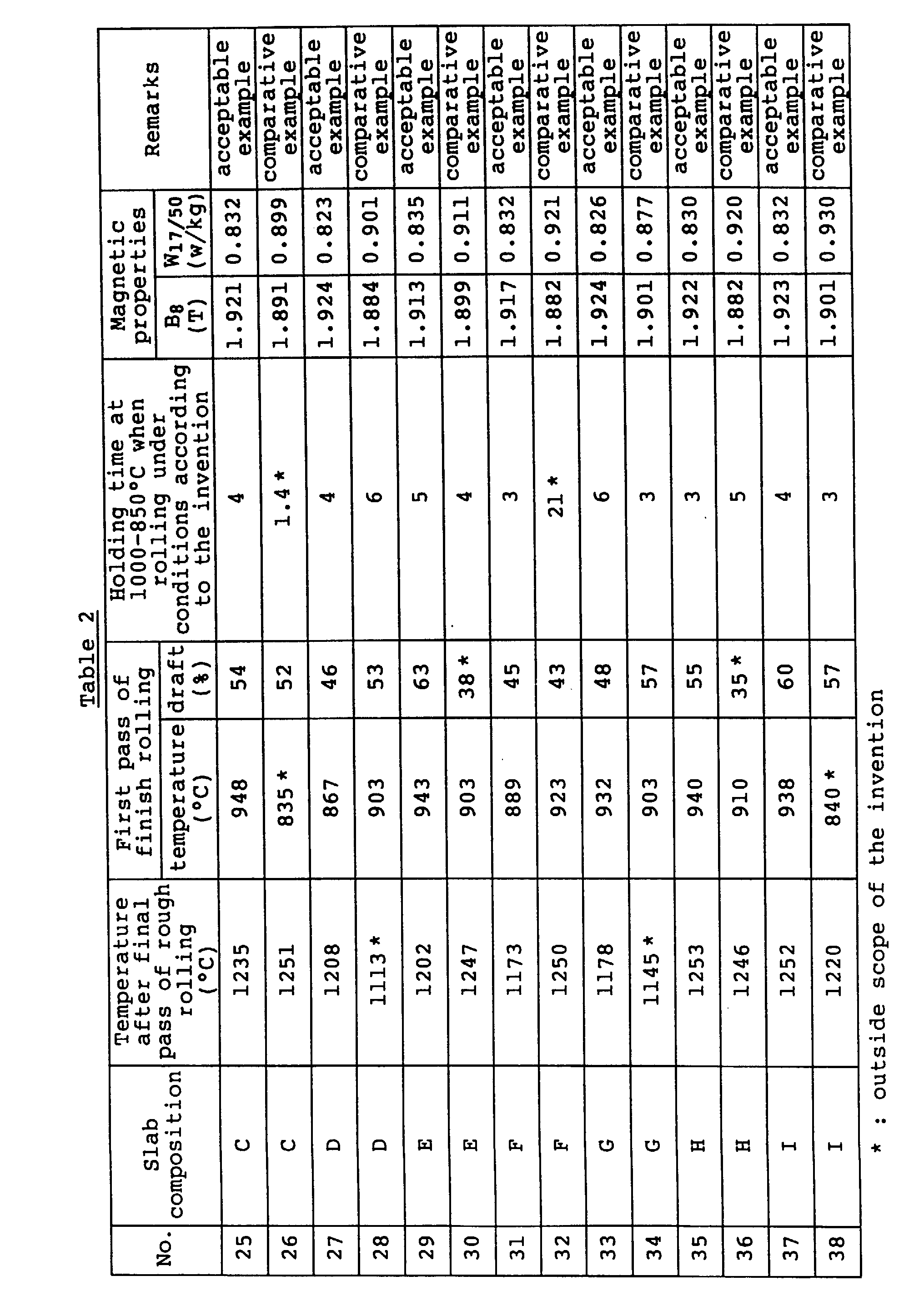
  • the temperature after the final pass of the rough rolling and conditions in first pass of the finish rolling are shown in Table 2.
  • the hot rolled steel sheet was pickled, subjected to first cold rolling and intermediate annealing and further to second cold rolling to obtain a cold rolled steel sheet having a final thickness of 0.23 mm. Thereafter, the cold rolled steel sheet was subjected to decarburization annealing, coated with a slurry of an annealing separator consisting mainly of MgO, and then subjected to a final finish annealing comprised of secondary recrystallization annealing and purification annealing to obtain a product.
  • Each of the above slabs was placed in a heating furnace, soaked in an N 2 atmosphere, and then subjected to a rough rolling just after the soaking.
  • the rough rolling was carried out through 5-6 passes in accordance with the slab thickness under such a condition that the draft at each pass was approximately equal, whereby a sheet bar of 30 mm in thickness was obtained. Then, the sheet bar was hot rolled in a tandem mill to obtain a hot rolled steel sheet of 2.0 mm in thickness.
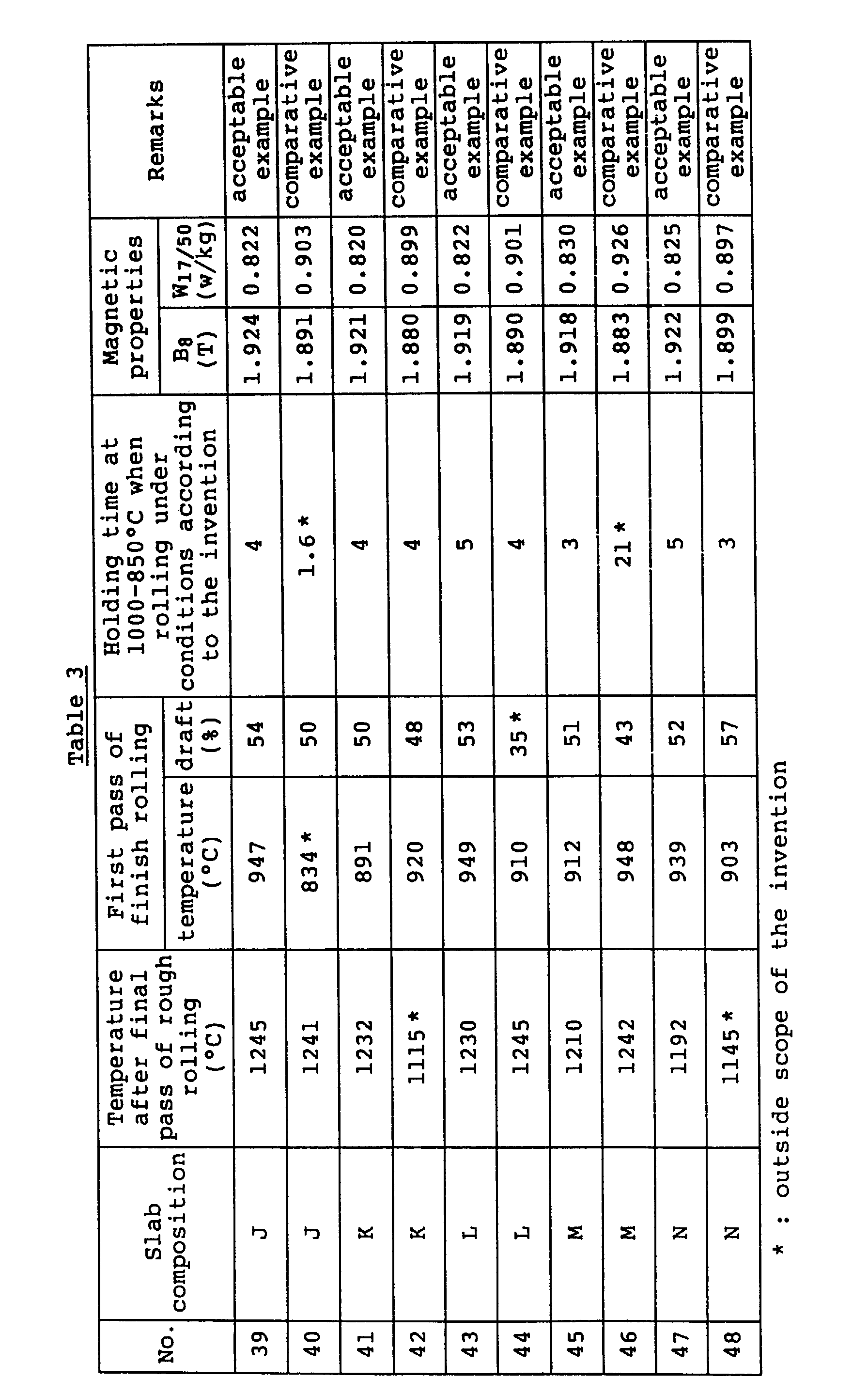
  • the temperature after the final pass of the rough rolling and conditions in first pass of the finish rolling are shown in Table 3.
  • the hot rolled steel sheet was pickled, subjected to first cold rolling and intermediate annealing and further to second cold rolling to obtain a cold rolled steel sheet having a final thickness of 0.23 mm. Thereafter, the cold rolled steel sheet was subjected to decarburization annealing, coated with a slurry of an annealing separator consisting mainly of MgO, and then subjected to a final finish annealing comprised of secondary recrystallization annealing and purification annealing to obtain a product.
  • Each of the above slabs was immediately placed in a gas heating furnace, soaked in an N 2 atmosphere, further placed into an induction heating furnace, at where a temperature difference between temperature of central portion being 1430°C and temperature of surface portion being 1370°C was sufficiently ensured, and immediately subjected to a rough rolling.
  • the rough rolling was carried out through 5-6 passes in accordance with the slab thickness under such a condition that the draft at each pass was approximately equal, whereby a sheet bar of 40 mm in thickness was obtained.
  • the surface was positively cooled during the rough rolling.
  • the sheet bar was hot rolled in a tandem mill to obtain a hot rolled steel sheet of 3.0 mm in thickness.
  • the surface of the sheet bar was sufficiently cooled with a high pressure water prior to the finish rolling.
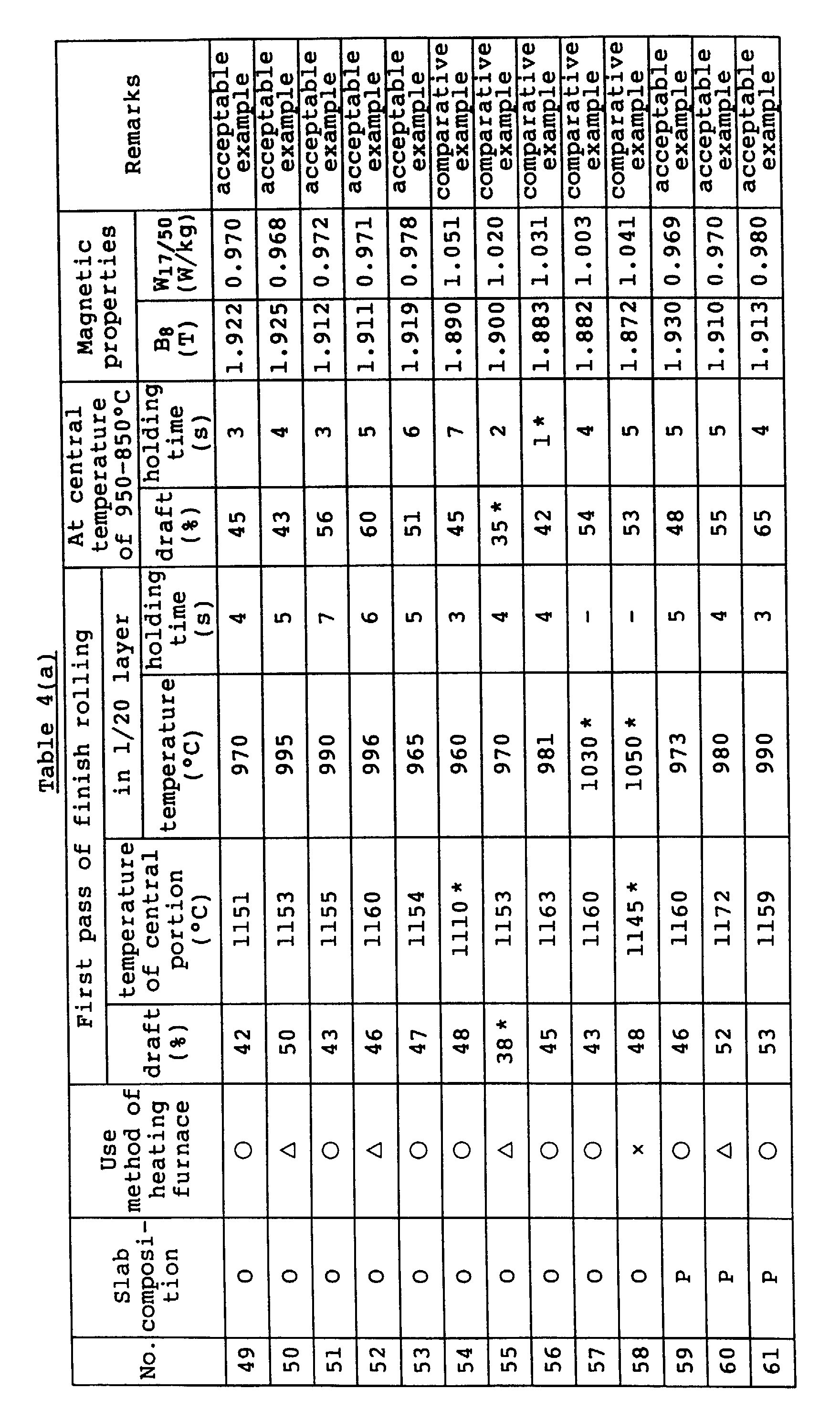
  • the conditions of the finish rolling are shown in Table 4.
  • the hot rolled steel sheet was pickled, subjected to first cold rolling and intermediate annealing and further to second cold rolling to obtain a cold rolled steel sheet having a final thickness of 0.23 mm. Thereafter, the cold rolled steel sheet was subjected to decarburization annealing, coated with a slurry of an annealing separator consisting mainly of MgO, and then subjected to a final finish annealing comprised of secondary recrystallization annealing and purification annealing to obtain a product.
  • Table 4 is also shown a case using no induction heating furnace. In this case, it is very difficult to take the temperature difference and the temperature difference between the surface layer and the central portion hardly ensures, so that the properties are not stably obtained.
  • a continuously cast slab comprising C: 0.043%, Si: 3.08%, Mn: 0.070%, Se: 0.022%, Sb: 0.020% and the reminder being substantially Fe was immediately placed in a gas heating furnace, soaked in an N 2 atmosphere to render the temperature of central portion into 1370°C and the temperature of surface portion into 1410°C, and immediately subjected to a rough rolling.
  • the rough rolling was carried out through 5-6 passes in accordance with the slab thickness under such a condition that the draft at each pass was approximately equal, whereby a sheet bar of 30 mm in thickness was obtained. Then, the sheet bar was hot rolled in a tandem mill to obtain a hot rolled steel sheet of 2.0 mm in thickness.
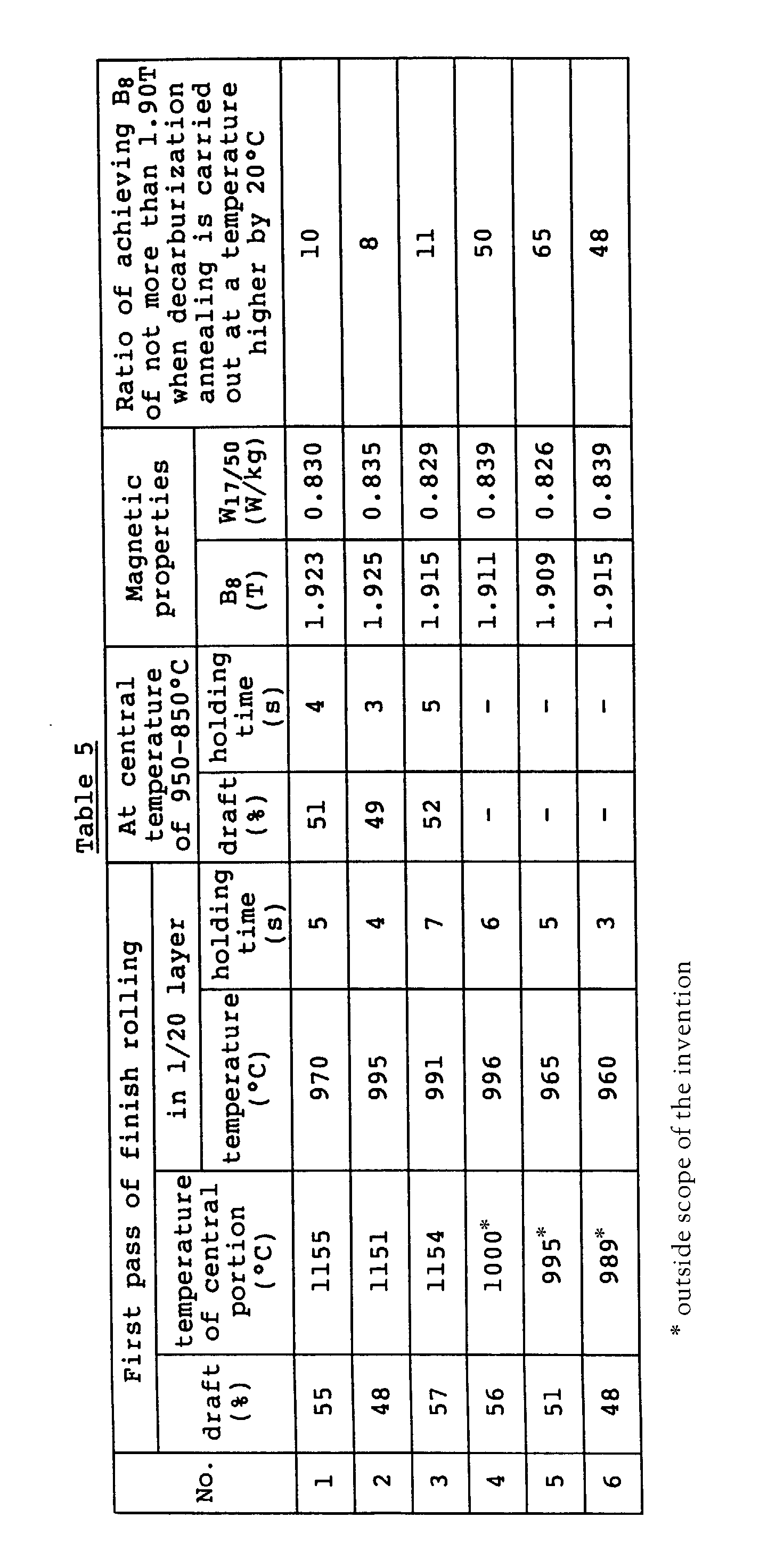
  • the conditions of the finish rolling are shown in Table 5.
  • each continuously cast slab having the above composition was immediately placed in a gas heating furnace, soaked in an N 2 atmosphere, further placed into an induction heating furnace, at where a temperature difference between temperature of central portion being 1430°C and temperature of surface portion being 1370°C was sufficiently ensured, and immediately subjected to a rough rolling.
  • the rough rolling was carried out under the same conditions as described above, whereby a sheet bar of 40 mm in thickness was obtained. Moreover, the surface was positively cooled during the rough rolling. Then, the sheet bar was hot rolled in a tandem mill to obtain a hot rolled steel sheet of 2.0 mm in thickness.
  • the conditions of the finish rolling are shown in Table 5.
  • the hot rolled steel sheet was pickled, subjected to first cold rolling and intermediate annealing and further to second cold rolling to obtain a cold rolled steel sheet having a final thickness of 0.23 mm. Thereafter, the cold rolled steel sheet was subjected to decarburization annealing, coated with a slurry of an annealing separator consisting mainly of MgO, and then subjected to a final finish annealing comprised of secondary recrystallization annealing and purification annealing to obtain a product.
  • a continuously cast slab comprising C: 0.040%, Si: 3.30%, Mn: 0.054%, Se: 0.022%, Sb: 0.024% and the reminder being substantially Fe was placed into a heating furnace, soaked in an N 2 atmosphere, and subjected to a rough rolling under conditions as shown in Table 6 immediately after the soaking, whereby a sheet bar of 30 mm in thickness was obtained.
  • the sheet bar was hot rolled in a tandem mill to obtain a hot rolled steel sheet of 2.0 mm in thickness.
  • the hot rolled steel sheet was pickled and subjected to first cold rolling - intermediate annealing -second cold rolling to obtain a cold rolled steel sheet having a final thickness of 0.23 mm.
  • the sheet was subjected to decarburization annealing, coated with a slurry of an annealing separator consisting mainly of MgO, and subjected to a final finish annealing comprised of secondary recrystallization annealing and purification annealing to obtain a product.
  • the secondary recrystallization uniformly proceeds in the widthwise direction to provide improved magnetic properties, and also the surface properties are good and further the uniformity of the magnetic properties in the longitudinal direction is excellent.
  • a continuously cast slab comprising C: 0.035%, Si: 2.98%, Mn: 0.072%, S: 0.018% and the reminder being substantially Fe was placed into a heating furnace, soaked in an N 2 atmosphere, and subjected to a rough rolling under conditions as shown in Table 7 immediately after the soaking, whereby a sheet bar of 35 mm in thickness was obtained.
  • the sheet bar was hot rolled in a tandem mill to obtain a hot rolled steel sheet of 2.4 mm in thickness.
  • the hot rolled steel sheet was pickled and subjected to first cold rolling - intermediate annealing - second cold rolling to obtain a cold rolled steel sheet having a final thickness of 0.35 mm.
  • the sheet was subjected to decarburization annealing, coated with a slurry of an annealing separator consisting mainly of MgO, and subjected to a final finish annealing comprised of secondary recrystallization annealing and purification annealing to obtain a product.
  • the secondary recrystallization uniformly proceeds in the widthwise direction to provide improved magnetic properties, and also the surface properties are good and further the uniformity of the magnetic properties in the longitudinal direction is excellent.
  • a continuously cast slab comprising C: 0.050%, Si: 3.10%, Mn: 0.078%, S: 0.024%, Al: 0.032%, N: 0.006% and the reminder being substantially Fe was placed into a heating furnace, soaked in an N 2 atmosphere, and subjected to a rough rolling under conditions as shown in Table 6 immediately after the soaking, whereby a sheet bar of 30 mm in thickness was obtained.
  • the sheet bar was hot rolled in a tandem mill to obtain a hot rolled steel sheet of 2.3 mm in thickness.
  • the hot rolled steel sheet was pickled and subjected to first cold rolling - intermediate annealing - second cold rolling to obtain a cold rolled steel sheet having a final thickness of 0.23 mm.
  • the sheet was subjected to decarburization annealing, coated with a slurry of an annealing separator consisting mainly of MgO, and subjected to a final finish annealing comprised of secondary recrystallization annealing and purification annealing to obtain a product.
  • the secondary recrystallization uniformly proceeds in the widthwise direction to provide improved magnetic properties, and also the surface properties are good and further the uniformity of the magnetic properties in the longitudinal direction is excellent.
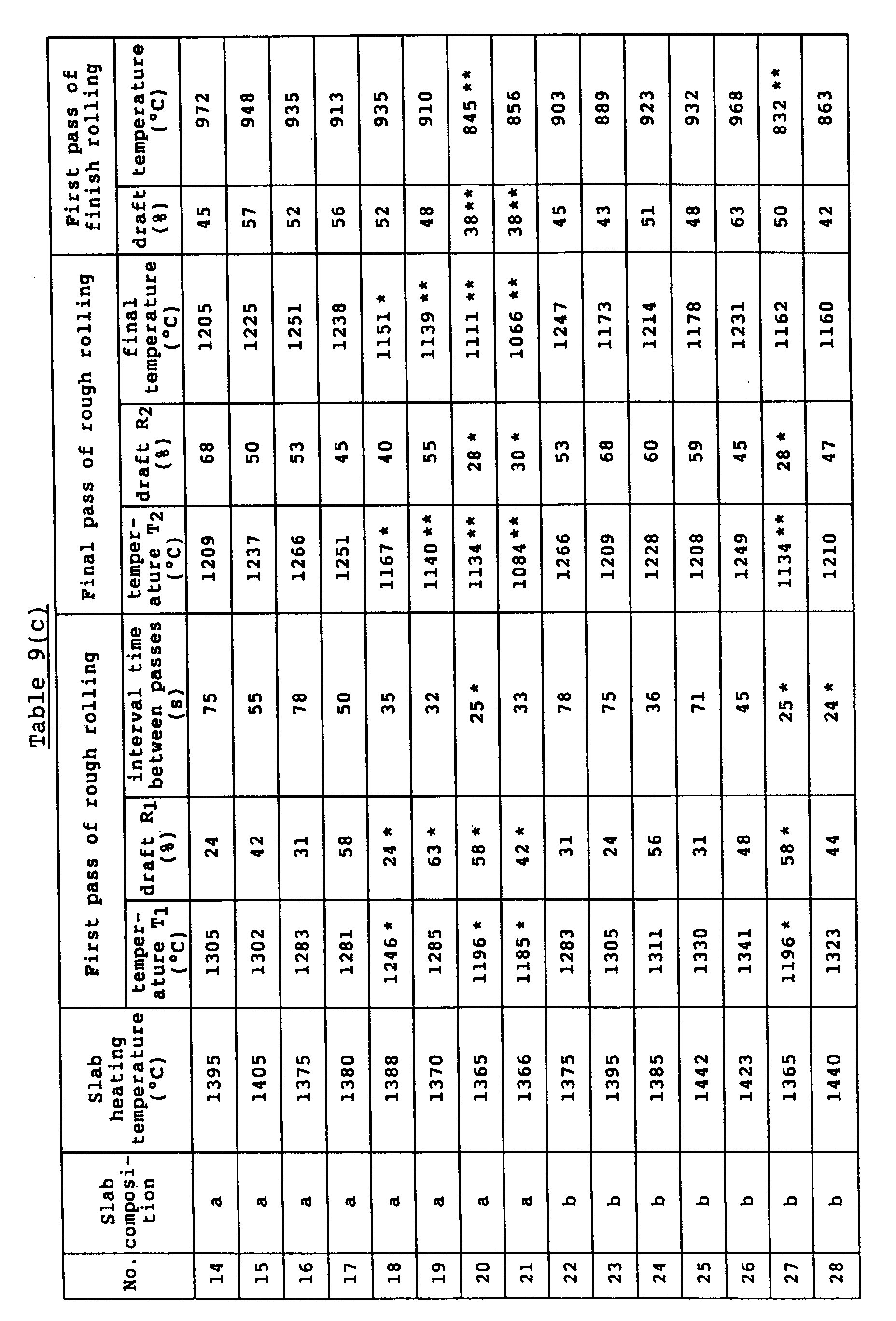
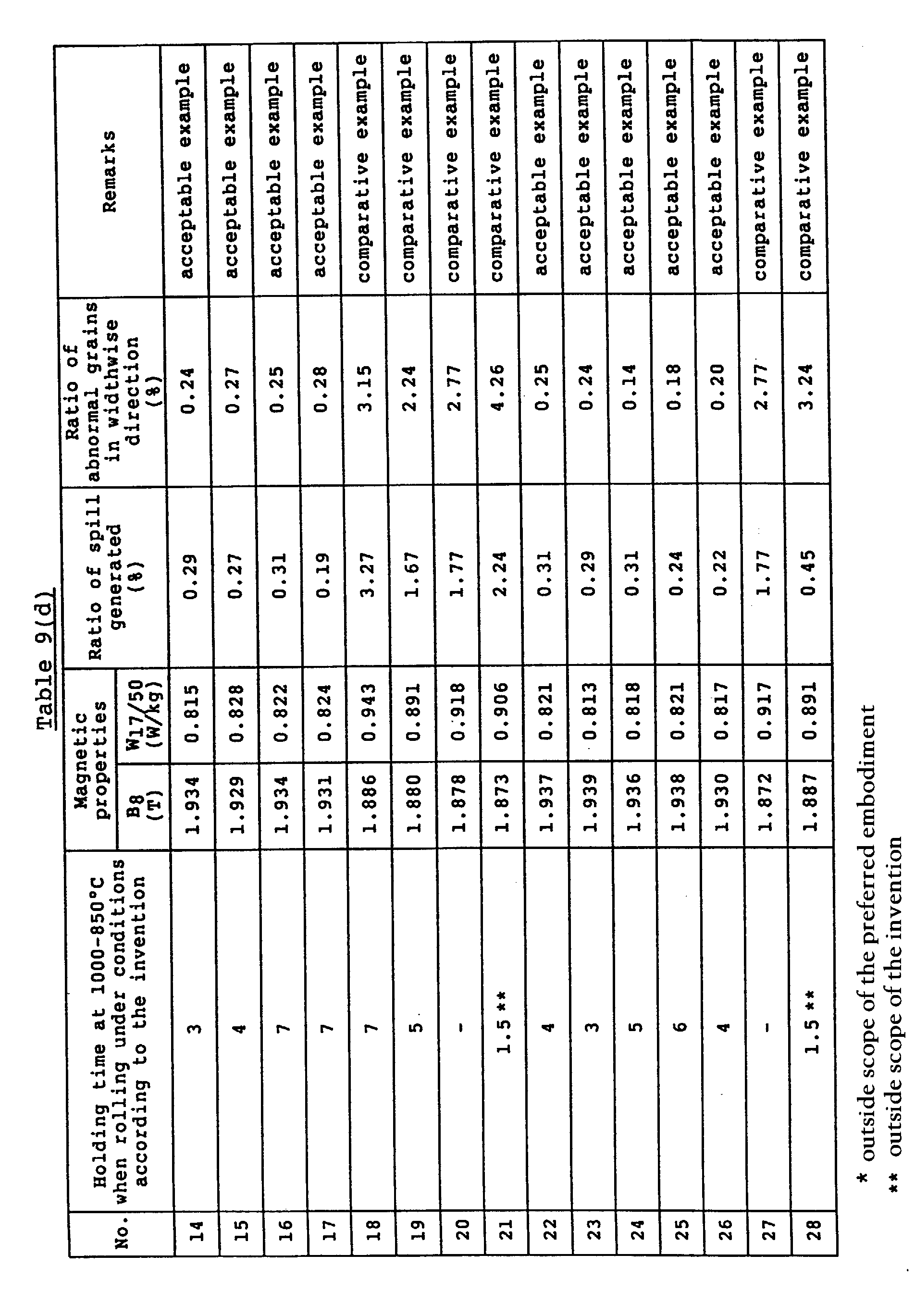
  • Each of the above slabs was placed in a heating furnace, soaked in an N 2 atmosphere, and immediately subjected to a rough rolling to obtain a sheet bar of 30 mm in thickness, which was hot rolled in a tandem mill to obtain a hot rolled steel sheet of 2.0 mm in thickness.
  • the rough rolling conditions and conditions of first pass in the finish rolling are shown in Table 9.
  • the hot rolled steel sheet was pickled and subjected to first cold rolling and intermediate annealing and further to second cold rolling to obtain a cold rolled steel sheet having a final thickness of 0.23 mm.
  • the sheet was subjected to decarburization annealing, coated with a slurry of an annealing separator consisting mainly of MgO, and subjected to final finish annealing comprised of secondary recrystallization annealing and purification annealing to obtain a product.
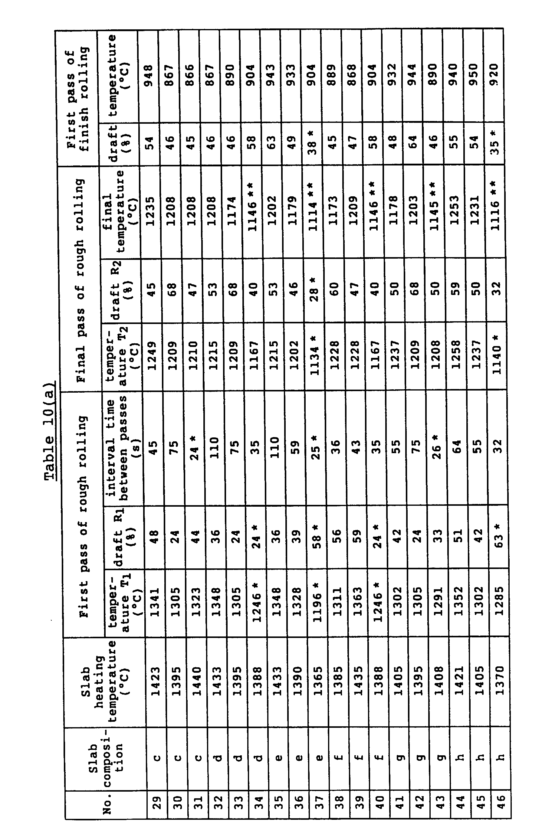
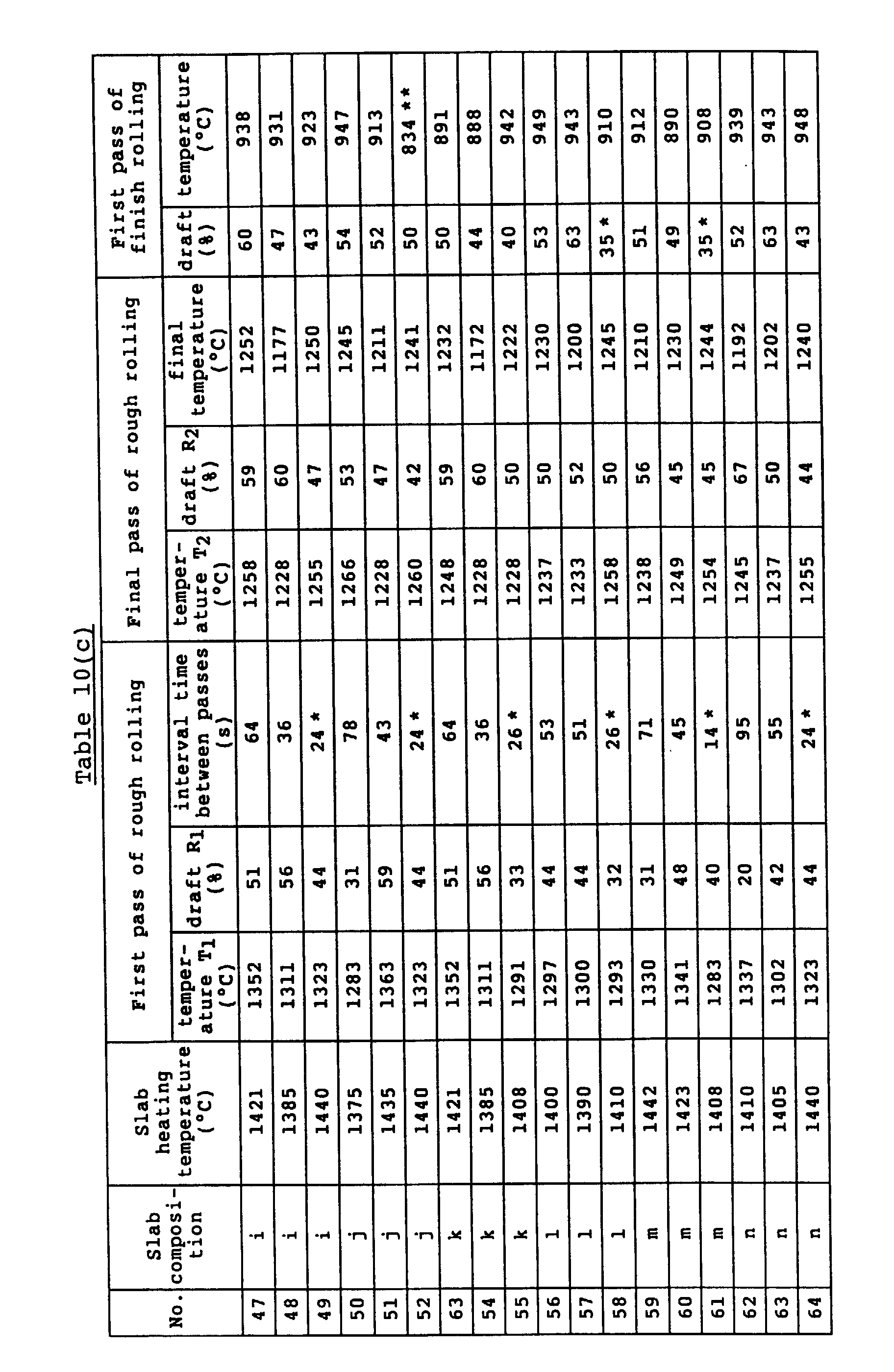
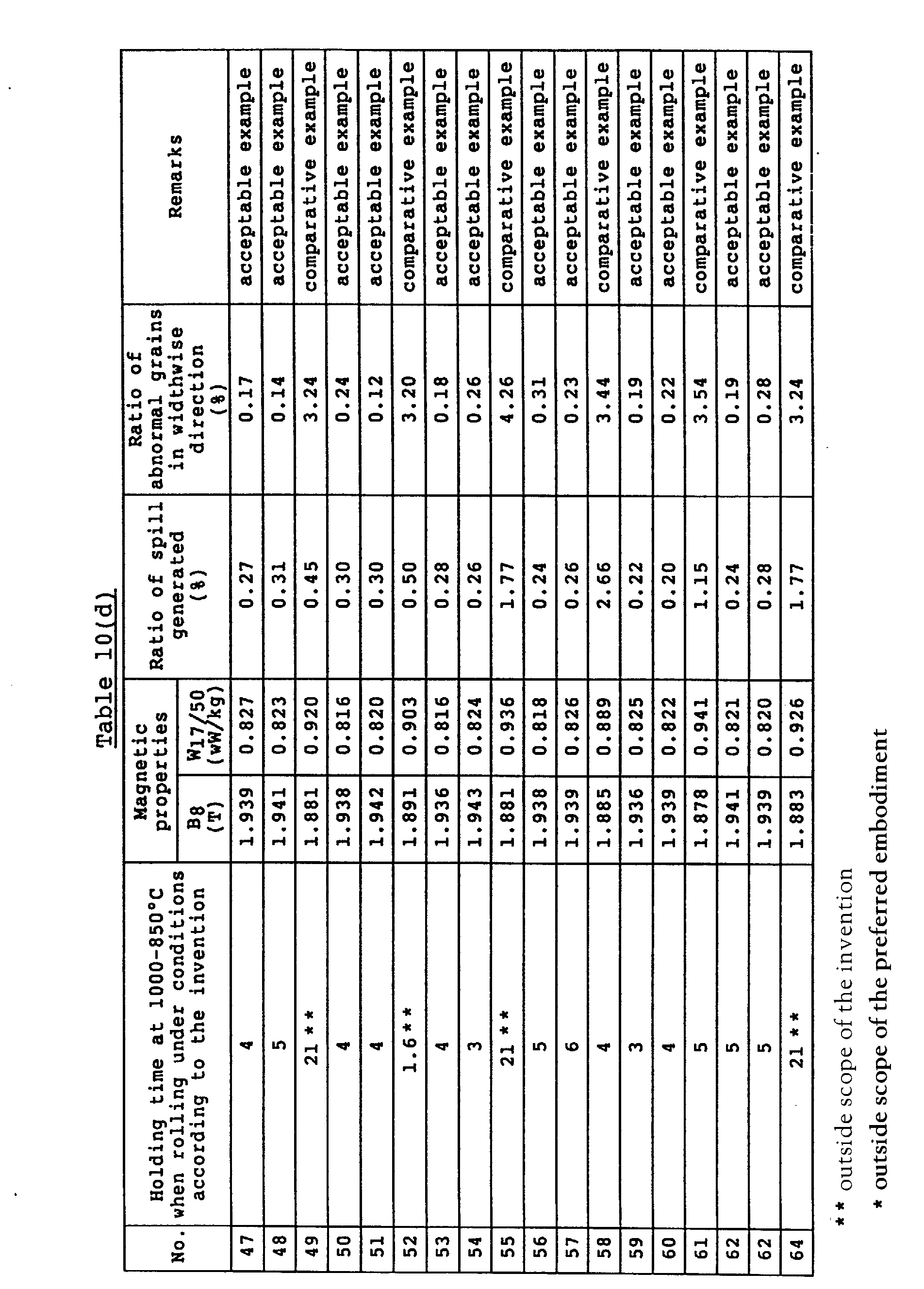
  • Each of the above slabs was placed in a heating furnace, soaked in an N 2 atmosphere, and immediately subjected to a rough rolling to obtain a sheet bar of 30 mm in thickness, which was hot rolled in a tandem mill to obtain a hot rolled steel sheet of 2.0 mm in thickness.
  • the rough rolling conditions and conditions of first pass in the finish rolling are shown in Table 10.
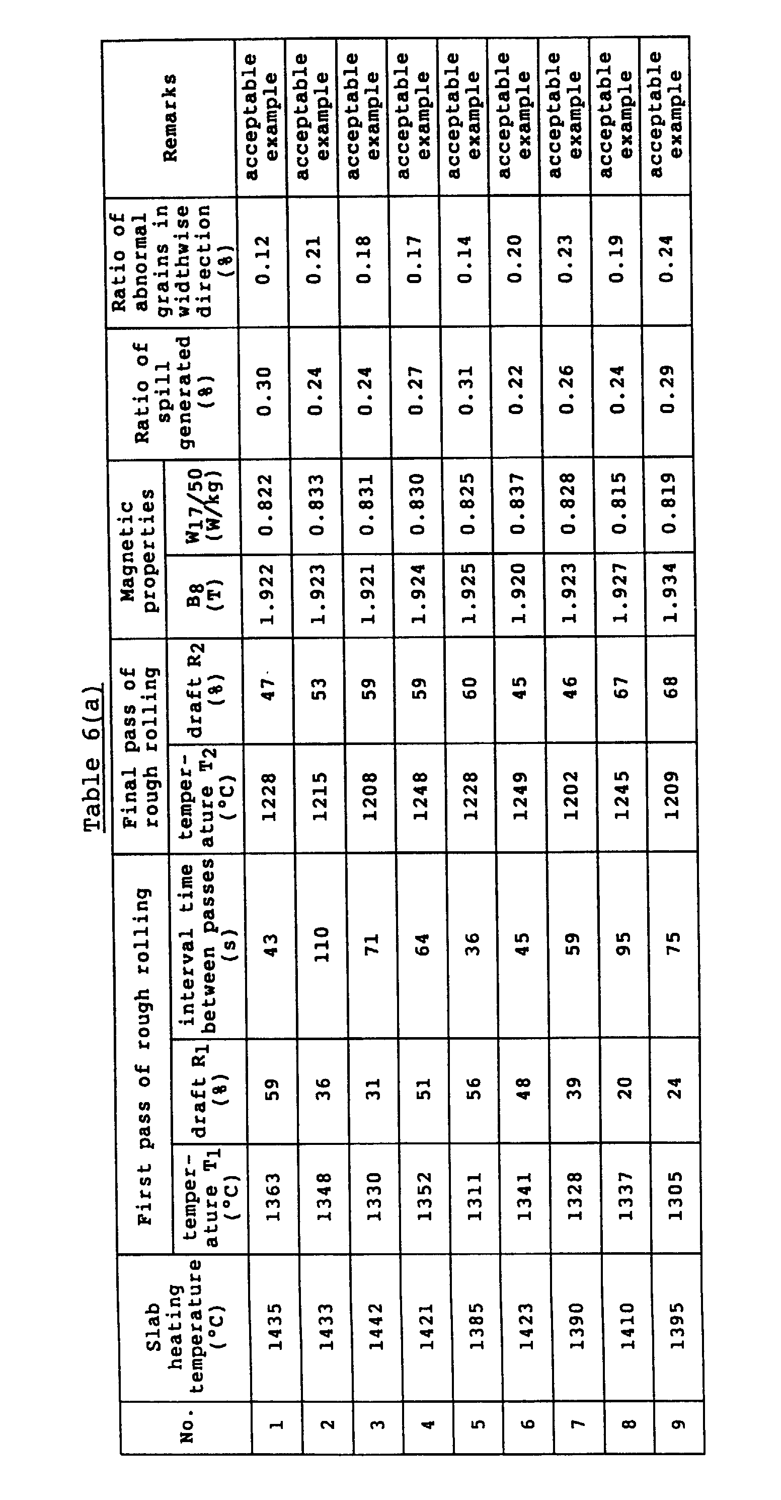
  • the hot rolled steel sheet was pickled and subjected to first cold rolling and intermediate annealing and further to second cold rolling to obtain a cold rolled steel sheet having a final thickness of 0.23 mm.
  • the sheet was subjected to decarburization annealing, coated with a slurry of an annealing separator consisting mainly of MgO, and subjected to final finish annealing comprised of secondary recrystallization annealing and purification annealing to obtain a product.
  • a continuously cast slab comprising C: 0.034%, Si: 3.01%, Mn: 0.070%, S: 0.017% and the reminder being substantially Fe was placed in a heating furnace, soaked in an N 2 atmosphere, and subjected to a rough rolling under conditions shown in Table 11 immediately after the soaking, whereby a sheet bar of 35 mm in thickness was obtained. Thereafter, the sheet bar was subjected to a finish tandem rolling under conditions shown in the same Table 11 to obtain a hot rolled steel sheet of 2.4 mm in thickness.
  • the hot rolled steel sheet was pickled and subjected to first cold rolling - intermediate annealing - second cold rolling to obtain a cold rolled sheet of 0.35 mm in thickness. Then, the sheet was subjected to decarburization annealing, coated with MgO, and subjected to a final finish annealing comprised of secondary recrystallization annealing and purification annealing to obtain a product.
  • Each of the above slabs was immediately placed in a gas heating furnace, soaked in an N 2 atmosphere, further placed into an induction heating furnace, at where a temperature difference between temperature of central portion being 1430°C and temperature of surface portion being 1370°C was sufficiently ensured, and immediately subjected to a rough rolling under conditions shown in Table 12, whereby a sheet bar of 30 mm in thickness was obtained. Moreover, the surface was positively cooled during the rough rolling. Then, the sheet bar was subjected to a finish tandem rolling under conditions shown in the same Table 12 to obtain a hot rolled steel sheet of 2.7 mm in thickness. Prior to the finish rolling, the surface of the sheet bar was sufficiently cooled with a high pressure water.
  • the hot rolled steel sheet was pickled, subjected to first cold rolling and intermediate annealing and further to second cold rolling to obtain a cold rolled steel sheet having a final thickness of 0.27 mm. Thereafter, the cold rolled steel sheet was subjected to decarburization annealing, coated with a slurry of an annealing separator consisting mainly of MgO, and then subjected to a final finish annealing comprised of secondary recrystallization annealing and purification annealing to obtain a product.
  • Table 12 is also shown a case using no induction heating furnace. In this case, it is very difficult to take the temperature difference and the temperature difference between the surface layer and the central portion hardly ensures, so that the properties become not stable.
  • a continuously cast slab comprising C: 0.043%, Si: 3.41%, Mn: 0.072%, Se: 0.020%, Sb: 0.020% and the reminder being substantially Fe was immediately placed in a gas heating furnace, soaked in an N 2 atmosphere render the temperature of central portion into 1370°C and the temperature of surface layer portion into 1410°C, and immediately subjected to a rough rolling under conditions shown in Table 13, whereby a sheet bar of 30 mm in thickness was obtained. Then, the sheet bar was subjected to a finish tandem rolling under conditions shown in Table 13 to obtain a hot rolled steel sheet of 2.0 mm in thickness.
  • the continuously cast slab having the above composition was immediately placed in a gas heating furnace, soaked in an N 2 atmosphere, further placed into an induction heating furnace, at where a temperature difference between temperature of central portion being 1430°C and temperature of surface portion being 1370°C was sufficiently ensured, and subjected to a rough rolling and finish rolling under conditions shown in Table 13, whereby a hot rolled steel sheet of 2.0 mm in thickness was obtained. Moreover, the surface was positively cooled during the rough rolling.
  • hot rolled steel sheets were pickled, subjected to first cold rolling and intermediate annealing and further to second cold rolling to obtain a cold rolled steel sheet having a final thickness of 0.23 mm. Thereafter, the cold rolled steel sheets were subjected to decarburization diannealing, coated with a slurry of an annealing separator consisting mainly of MgO, and then subjected to a final finish annealing comprised of secondary recrystallization annealing and purification annealing to obtain products.
  • grain oriented silicon steel sheets having improved magnetic properties over a whole of the steel sheet and good surface properties can stably be produced.
  • the merits of the hot strip mill can be utilized at maximum in the production of the grain oriented silicon steel sheet, so that not only the improvement of the productivity but also the energy-saving can be achieved.

Landscapes

  • Chemical & Material Sciences (AREA)
  • Engineering & Computer Science (AREA)
  • Physics & Mathematics (AREA)
  • Crystallography & Structural Chemistry (AREA)
  • Thermal Sciences (AREA)
  • Manufacturing & Machinery (AREA)
  • Electromagnetism (AREA)
  • Mechanical Engineering (AREA)
  • Materials Engineering (AREA)
  • Metallurgy (AREA)
  • Organic Chemistry (AREA)
  • Manufacturing Of Steel Electrode Plates (AREA)
  • Soft Magnetic Materials (AREA)

Description

SPECIFICATION TECHNICAL FIELD
This invention relates to a method of producing grain oriented silicon steel sheets having improved magnetic properties.
BACKGROUND ART
As is well-known, grain oriented silicon steel sheets are mainly used as the material for iron cores in transformers and other electrical machinery and equipment and are comprised of secondary recrystallized grains aligned {110} face to the plate face and <001> axis to the rolling direction. In order to develop the secondary recrystallized grains having such a crystal orientation, it is required that precipitates such as MnS, MnSe, AlN and the like called inhibitors are uniformly and finely dispersed in the steel to effectively suppress the growth of crystal grains in an orientation other than {110}<001> orientation during the final annealing at a high temperature. Therefore, the control of the inhibitor dispersed state is carried out by solid-soluting these precipitates during the slab heating prior to hot rolling and then subjecting it to hot rolling having a proper cooling pattern.
Here, an important role of the hot rolling lies in that the solid-soluted inhibitor components are finely and uniformly precipitated as an inhibitor.
For example, Japanese Patent laid open No. 53-39852 has reported that a proper dispersion phase of MnSe is obtained by holding the temperature within a range of not lower than 850°C but not higher than 1200°C for 60-360 seconds. In this method, however, the inhibitor is non-uniformly and coarsely precipitated in a fair frequency. Particularly, it is known from experience that the inhibitor becomes considerably coarse when being held at about 1100°C for a long period of time. Therefore, by this method it is difficult to provide a complete secondary recrystallized structure because the inhibiting force of the inhibitor lowers.
Furthermore, Japanese Patent Application Publication No. 58-13606 has proposed a method wherein the steel sheet is cooled at a cooling rate of not less than 3°C/s while being continuously subjected to hot rolling within a temperature range of 950-1200°C at a draft of not less than 10%. In this method, however, the inhibitor is not always finely precipitated, and the coarse or non-uniform precipitation of the inhibitor is caused in accordance with the size of the crystal grains. Particularly, the dispersion in the direction of the sheet thickness is apt to become non-uniform. As a cause of this, there has been mentioned a non-uniformity of strain inherent to high temperature deformation.
In these conventional methods, the dispersed state of the inhibitor can not be completely rendered into a fine and uniform state, and the normal growth of the primary crystal grain can not effectively be controlled at the secondary recrystallization annealing step in the final finish annealing, so that the complete secondary recrystallization structure can not be obtained.
Another important role of hot rolling lies in that the slab cast structure is made fine by recrystallization to form a structure most suitable for secondary recrystallization. Moreover, such a treatment for fining the crystal structure has hitherto been carried out separately from the solid solution treatment of the inhibitor.
As to the solid solution of the inhibitor, it has hitherto been reported, for example, in Japanese Patent laid open No. 63-10911 that grain oriented silicon steel sheets having less surface defects and good properties are obtained by raising the slab surface temperature above 1320°C to a temperature of 1420-1495°C at a temperature rising rate of not less than 8°C/min and holding the slab surface temperature within a range of 1420-1495°C for 5-60 minutes. According to this method, the complete solid solution of the inhibitor has certainly been achieved and also the coarsening of the slab surface grains can be suppressed in principle to improve the surface properties, but it is actually difficult to uniformly satisfy the above condition with a heavy article such as slab or the like, and particularly it is impossible in fact to completely suppress the coarsening of the crystal grains over the full length of the slab. Therefore, in order to ensure the uniformity of the structure, it is required to add any treatment for finely dividing the crystal grains during the hot rolling.
On the other hand, as to the formation of the fine structure, there are known many methods, i.e. a method of rolling under a high draft through recrystallization within a temperature range of 1190-960°C (Japanese Patent laid open No. 54-120214), a method of rolling under a high draft of not less than 30% at a state containing not less thank 3% of γ-phase within a temperature range of 1230-960°C (Japanese Patent laid open No. 55-119216), a method of restricting a starting temperature for rough rolling to not higher than 1250°C (Japanese Patent laid open No. 57-11614), a method of rolling at a strain rate of not more than 15 s-1 and a draft of not less than 15%/one pass within a temperature range of 1050-1200°C (Japanese Patent laid open No. 59-93828), and the like. These methods have the common feature that the formation of the fine structure is carried out by rolling under a high draft at a temperature region of about 1200°C. That is, they are based on knowledge of the recrystallization limit reported in "Tetsuto-Hagane", 67 (1981) S 1200 or are based on the same technical idea as described above. Fig. 4 shows this knowledge. From this figure, it can be understood that rolling at high temperature does not substantially contribute to the recrystallization and only the application of large strain at a low temperature recrystallization region contributes to the recrystallization. Therefore, it is necessary to conduct the rolling after cooling to a temperature not higher than 1250°C in order to form the fine structure through recrystallization even in slabs heated to high temperature (see also JP-A-61 12822).
In all of the above techniques, the heating temperature is not lower than 1250°C, and the upper limit thereof is not particularly restricted, so that it is a common feature that the inhibitor is solid-soluted by holding in a furnace for a long period of time while allowing the grain growth of the slab to a certain extent and the crystal grains are finely divided by hot rolling.
Considering the actual state of these methods however, when the slab is heated at a high temperature for completely solid-soluting the inhibitor, it is required not only to arrange a cooling means at the upstream side of the hot strip mill but also to take extra mill power for conducting the hot rolling at a low temperature, which is conflicting with the idea of the hot strip mill which is to achieve energy-saving and high productivity. Furthermore, the effect of the rolling at the low temperature is not necessarily clear.
That is, when the above method is applied to actual steps, many problems exist even though the effect is developed to a certain extent.
DISCLOSURE OF THE INVENTION
A first object of the invention is to provide a method of advantageously producing grain oriented silicon steel sheets, in which improved magnetic properties are stably obtained by conducting sufficiently uniform and fine dispersion of the inhibitor at the hot rolling step.
A second object of the invention is to provide a method of advantageously producing grain oriented silicon steel sheets having improved magnetic properties and further surface properties, in which a fine and uniform crystal structure is reliably obtained while utilizing the mass production advantage of the hot strip mill to a maximum even under conditions of high-temperature slab heating needed for the complete solid-solution of the inhibitor and the improvement of surface properties.
According to the present invention there is provided a method of producing a grain oriented silicon steel sheet having improved magnetic properties by a series of steps including subjecting a slab of silicon> containing steel to hot rolling comprising rough rolling and subsequent finish rolling after heating, subjecting the hot rolled sheet to a heavy cold rolling or to cold rolling twice with an intermediate annealing to a final sheet thickness, subjecting the cold rolled sheet to decarburization annealing, applying a slurry of an annealing separator to a surface of the decarburised steel sheet, and subjecting the thus treated sheet to a final finish annealing, said method having the features of the hot rolling step indicated in claim 1.
In an embodiment, at the finish rolling stage in the hot rolling step, said steel sheet is cooled while holding the temperature of the central portion of said steel sheet in the thickness direction above 1150°C, and when the temperature of a zone positioned below the surface at a depth corresponding to 1/20 of the sheet thickness reaches a temperature range of 1000-950°C, the steel sheet is rolled at a draft of not less than 40% and held at the above temperature range for 3-20 seconds and then cooled, and when the temperature of the central portion reaches a temperature range of 950-850°C, the steel sheet is rolled at a draft of not less than 40% and held at this temperature range for 2-20 seconds.
In another embodiment, at the rough rolling stage in said hot rolling step, a first pass is carried out under conditions that the rolling temperature T1 is not lower than 1280°C and the draft R1 satisfies the following equation: 60 ≧ R1(%) ≧ -0.5T1 + 670 and these conditions are held up to the next pass for not less than 30 seconds, and a final pass is carried out under conditions that the rolling temperature T2 is not lower than 1200°C and the draft R2 satisfies the following equation: 70 ≧ R2(%) ≧ -0.1T2 + 165
In a further embodiment, the slab is heated to such a temperature that the temperature in the central portion of said slab is not less than 1370°C.
The invention will be described with respect to experimental results.
At first, experimental results relating to the achievement of a uniform and fine dispersion of the inhibitor will be described.
In general, when an element forming an inhibitor such as Se or the like is precipitated and grown as MnSe or the like at a cooling stage after the solid solution treatment, it has been proposed to control the size and average interval of the precipitated grains by the cooling rate, holding temperature and holding time. However, detail of the precipitation behavior required for the above control during the hot rolling is not very clear up to the present, and particularly the relationship between the hot strain and the precipitation of inhibitor is not clear, so that the inhibitor could not uniformly and finely be precipitated over the full surface of the steel sheet.
on the contrary, the inventors have made various studies with respect to the precipitation behavior of the inhibitor at various temperature regions and found out that the precipitation behavior of the inhibitor largely changes in accordance with the strain quantity applied at a high temperature and the holding time at this temperature.
The inventors have made an experiment in a laboratory wherein Se was completely solid-soluted by heating a steel slab and then strain was applied at each temperature region and this temperature was held for a given time. In this case, the strain quantity was varied by adopting a draft of 0-70% and also the holding time was varied. From this experiment, it was understood that the precipitation behavior of the inhibitor, in which the precipitation rate was increased by applying strain, was entirely different from the case where no strain was applied. That is, the experiment where no strain was applied was unsuitable for investigating the precipitation of inhibitor in the hot rolling. Furthermore, it was found that when the sheet was once cooled to room temperature at the cooling stage before the precipitation treatment, the behavior was largely different from that in the original cooling stage. Therefore, the experiment was carried-out by applying a proper hot working strain under an accurate heat cycle.
An example of such an experiment will be described below.
A slab of silicon steel comprising C: 0.045 wt% (hereinafter shown by % simply), Si: 3.25%, Mn: 0.07%, Se: 0.020% and the reminder being substantially Fe and having a thickness of 30 mm was subjected to a solid solution treatment at 1350°C for 30 minutes and rapidly cooled to a temperature giving a hot working strain, and then strain was applied by rolling at a draft of 50% and held at the above temperature for various times.
In Fig. 1 of the accompanying drawings is shown the results of studies on the influences exerted by the rolling temperature on the precipitation state of the inhibitor and the holding time at such a temperature.
Moreover, when the sheet was treated in the same cooling pattern without applying strain, no precipitation of the inhibitor was caused till the holding time was 60 seconds, so that the effect by the application of strain is very large, and it has been confirmed that the introduction of strain is indispensable for the precipitation of inhibitor in the hot rolling.
From Fig. 1, it is clear that non-uniform and coarse precipitation is caused by applying strain at a temperature region exceeding 1000°C. However, no precipitation of inhibitor is caused when the temperature exceeds 1150°C.
On the contrary, the inhibitor is finely and uniformly precipitated at the temperature region of 1000-850°C, and in this case it has been confirmed that a holding time of not less than 2 seconds is required. However, when the holding time is too long, the precipitated size of the inhibitor becomes larger, which produces a reduction in the controlling force. Therefore, a holding time exceeding 20 seconds is not favorable.
Furthermore, it has been found from Fig. 1 that the inhibitor is non-uniform and coarsely precipitated at high temperature, while the inhibitor is uniformly and finely precipitated at lower temperature as shown by the non-uniform precipitation region (1), coarse precipitation region (2) and uniform and fine precipitation region (3).
As shown by schematic view (1) of Fig. 1, the precipitation behavior at high temperature is understood to center the precipitation onto dislocations introduced by the hot working strain and to be influenced by the dislocation density inside the crystal. For this end, the inhibitor is apt to precipitate on the grain boundary and the subgrain boundary, and uniform precipitation in the grains hardly occurs. On the contrary, the precipitation behavior at low temperature as shown by schematic view (3) is caused irrespective of the dislocation inside the grain, so that the precipitation becomes uniform inside the grains. The precipitation behavior at low temperature is considered to be precipitation onto lattice defects introduced by the working strain, which is more uniform and finer than precipitation onto dislocations observed at high temperature, so that the inhibitor is uniformly and finely precipitated over the full surface of the steel sheet. In this connection, the feature that precipitation onto the dislocations becomes large at high temperature is considered to be due to the fact that the lattice defect introduced during the working rapidly dislocates and moves onto the subgrain boundary and the grain boundary at high temperature.
The quantity of hot working strain required is approximately the quantity introduced by rolling at a cumulative draft of not less than 40% within the above temperature range. The reason for this is that the strain quantity introduced into the crystal grains of the steel sheet actually differs for every grain. The difference in the strain quantity between grains becomes large at a light draft and thus there is the fear of differing dispersion precipitation states of the inhibitor in every grain.
The following has been found from the above experimental results.
That is, when the hot strain is applied at a temperature region of 1000-850°C, the precipitation nucleus of the inhibitor is formed at a very fast speed over the full surface inside the grain, and also the precipitation is completed by holding at this temperature range for 2-20 seconds, in which the dispersion state of the inhibitor in any crystal grain becomes fine and uniform. That is, the completely fine and uniform precipitation of the inhibitor is achieved over the full surface of the steel sheet, and hence products having very excellent magnetic properties are obtained.
Although the uniform and fine dispersion of the inhibitor is achieved by the aforementioned treatment, when the surface state of the steel sheet changes in accordance with the change of annealing temperature at subsequent steps for example, at the primary recrystallization annealing step, the inhibitor existing in the vicinity of the surface is apt to become unstable. Therefore, in order to stably produce a product having improved magnetic properties on an industrial scale, it has been found that it is required to minutely control the dispersion precipitation state of the inhibitor in the direction of sheet thickness.
The inventors have made studies on the results shown in Fig. 1 in detail and found that slightly large inhibitor is obtained at high temperature even in the uniform precipitation region. That is, it has been found that when strain is applied at a temperature region of 1000-950°C and this temperature region is held for not less than 3 seconds, uniform but slightly large inhibitor is obtained. This is considered to be due to the fact that even in the uniform precipitation region, the higher temperature is less favourable for nucleus formation for the starting of precipitation and favours fast diffusion so that the inhibitor grows somewhat as compared to at the lower temperature.
Therefore, the size of the inhibitor can be controlled by utilizing the above behavior.
As a result of studies on the stabilization of the inhibitor near to the surface, it has been confirmed that when the size of the inhibitor near to the surface is made somewhat large, the change in the inhibitor component such as decomposition due to diffusion from the surface or the like at the subsequent steps hardly occurs. Concretely, when the temperature of a layer positioned from the surface at a depth corresponding to 1/20 of the sheet thickness (hereinafter referred to as 1/20 layer) is within the range of 1000-950°C, the best result is found to be obtained by applying strain and then holding this temperature range for 3-20 seconds. Thus, as the temperature of the 1/20 layer and the precipitation state of inhibitor near to the surface can be confirmed to be interrelated, it has been clarified that the precipitation of the inhibitor near to the surface can also be controlled by controlling the temperature of the 1/20 layer.
In brief, in order to finely and uniformly precipitate the inhibitor, the application of working strain at the temperature region of 950-850°C is sufficient, while in order to uniformly precipitate slightly large inhibitor, it is enough to apply the working strain at the temperature region of 1000-950°C.
Therefore, it is possible to separately control the dispersion state of the inhibitor in the vicinity of the surface and the central portion by using the above means, and the controlling force can reliably be maintained in the secondary recrystallization annealing without changing the surface inhibitor in the primary recrystallization annealing and the decarburization annealing.
In the actual hot rolling step, the slab is heated by gas and then the temperature in the central portion of the slab is raised above 1370°C in an induction heating furnace to sufficiently ensure a temperature difference with respect to the surface and completely solid-solute the inhibitor component, and thereafter the silicon steel sheet is cooled with water at the sheet bar stage in the rough rolling to further adjust the surface and central temperatures.
Then, when the temperature near to the surface or temperature located in the layer corresponding to 1/20 of the sheet thickness is within a range of 1000-950°C while holding the temperature in the central portion of the sheet above 1150°C during the finish rolling, the working strain is applied at a draft of not less than 40% and subsequently the above temperature range is held for 3-20 seconds. Further, when the temperature in the central portion is within a range of 950-850°C by cooling with water, the working strain is applied at a draft of not less than 40% and the holding time at this temperature range is held for 2-20 seconds to complete the hot finish rolling.
Fig. 2 of the accompagnying drawings shows a preferable example of temperature hysteresis in the finish rolling. Moreover, the temperatures at the 1/20 layer and the central layer were accurately simulated by means of a computer using finite element method.
That is, when the temperature of the central portion is not lower than 1150°C and the temperature of the 1/20 layer is slightly lower than 1000°C, a first pass of the finish rolling is carried out to ensure the holding time of at least 3 seconds till the temperature of the 1/20 layer is lower than 950°C. Moreover, further rolling may be carried out during the holding time. Then, when the temperature of the central portion is within a temperature range of 950-850°C, the rolling is carried out at a draft in total of not less than 40%. Moreover, the rolling may be one pass or a plurality of passes. In brief, the draft of not less than 40% may be applied at each of the above temperature ranges.
According to this embodiment of the invention, it is important that the difference in the temperature between the surface layer and the central portion just before the finish rolling is sufficiently held. For this end, it is preferable to sufficiently raise the temperature of the central portion by induction heating. In order to ensure the difference in temperature between the central portion and the surface layer portion, it is preferred that the surface layer portion is positively cooled with water at the sheet bar stage.
As previously mentioned, the achievement of the formation of fine crystal grains at the higher temperature region is very useful for utilizing the mass production advantages of the hot strip mill.
The inventors have made many experiments and studies on recrystallization behavior at the high temperature region and have newly found that the recrystallization fully proceeds when the strain quantity is sufficiently large even at the high temperature region which has hitherto been considered as a strain recovering region and not of interest. In this regard, there has been no report up to the present. The reason for this is that high temperature heating was difficult in industry, and even when being examined in a laboratory, it was required to conduct the high temperature heating for high temperature rolling, but there were caused problems such as scale formation, damage to the experimental furnace and the like, and such a high temperature heating was very difficult.
Moreover, there are many experimental reports on ordinary steels. In this case, the high temperature region above 1200°C is a dynamic restoring region and is mainly a restoring or dynamic recrystallization region, so that studies beyond these reports have not sufficiently been made. Particularly, almost all of the grain oriented silicon steels are α-phase because they contain about 3% of Si. Since the α-phase is considered to be easily restored, it seems that dynamic recrystallization does not occur in the grain oriented silicon steel which is entirely outside the object of interest.
However, the inventors have questioned this common view and have developed a high temperature furnace capable of heating at a superhigh temperature and having a less influence on scale and have made various studies using such a high temperature furnace, and as a result the aforementioned results have been first accomplished.
An experiment illustrating these results will be described below.
A slab of silicon steel comprising C: 0.04%, Si: 3.36%, Mn: 0.05%, Se: 0.022% with the reminder being substantially Fe was heated at 1350°C for 30 minutes, rolled at various temperatures under various drafts using one pass and cooled with water. Thereafter the sectional structure was observed to measure the recrystallinity.
The measured results are shown in Fig. 3 of the accompagnying drawings which is a graph showing the relation between rolling temperature and draft.
As seen from this figure, it has been confirmed that the recrystallization proceeds if the draft is not less than 30% even at a high temperature region, for example, 1350°C which has been considered to generate no recrystallization in the conventional knowledge. And also, it has been found that the complete-region of recrystallization is further enlarged by holding the temperature for not less than 30 seconds, preferably not less than 60 seconds after the rolling.
Such a phenomenon is understood as follows.
At first, it has been observed that subgrains constituted by rough network-like dislocation structure are formed in the unrecrystallized grain after the rolling. Therefore, it is guessed that the restoring terminates at a fairly fast time after the rolling. Furthermore, it is considered that the roughness of the network or dislocation density is different in the crystal grains so that such a difference of dislocation density is a driving force of the recrystallization. Since the grain boundary may be moved by thermal activation at the high temperature, if the moved grain has a curvature of not less than a certain value, it may be a nucleus for recrystallization.
As a result of the above phenomenon, it has been clarified that recrystallization is actually possible even at the high temperature region which has hitherto been considered to store insufficient strain to cause dynamic recrystallization. Moreover, in this recrystallization behavior, the dislocation density of the unrecrystallized region is low as mentioned above, so that the driving force for the growth of the above region is very small. However, when the mobility of the grain boundary is very large or when the temperature is high (not lower than 1280°C), recrystallization is sufficiently possible even though time is required to a certain extent.
This phenomenon is considerably different from the conventionally well-known static recrystallization.
The aforementioned fact involves rolling 3% silicon steel at a temperature region above 1300°C or a recrystallization mechanism at a single α-phase state, which is first revealed at this time. On the contrary, the recrystallization limit curve conventionally well-known in 3% silicon steel as shown in Fig. 4 of the accompagnying drawings involves hard γ-phase precipitates and recrystallization proceeds only in the vicinity thereof. That is, the data are obtained by rolling experiments in the conventional technique, but the influence of the heat treating method prior to the rolling is omitted, so that it is considered that the results are different from the experimental results making the basis of the invention. This is considered to be due to the fact that the sample solid-soluted at high temperature was once cooled to room temperature and then reheated to the given rolling temperature for the rolling. In this case, γ-phase is always and partly produced in the structure. This γ-phase is preferentially produced near to the boundary of α-grains, where the recrystallization easily proceeds. Even in this case, however, when the original grain size is large as in the grains of the cast slab, the recrystallization hardly completes, and the unrecrystallized portion is always apt to be left in the central portion of the original grain. Furthermore, the percentage and dispersion of γ-phase are largely dependent upon not only the temperature but also the C and Si amounts as well as the strain quantity and cooling rate (holding time). Therefore, it is known that the effect largely changes even with a slight change of the treating condition. This is guessed to be the main reason why the effect of finely dividing grains by low temperature hot rolling is not reliably obtained in the conventional technique. On the other hand, there is a drawback that the increase of C amount (increase of coarse carbide) hardly provides the rolling structure having a high alignment in the subsequent steps.
On the contrary, the recrystallization behavior in the single α-phase region at high temperature found by the inventors is different from the conventional recrystallization at low temperature in the presence of γ-phase, in which the forming site of recrystallization nucleus is not γ-phase but is merely the grain boundary. Furthermore, the size of the recrystallized grain is apt to become relatively large, so that the unrecrystallized portion hardly remains and the uniform recrystallized grain structure is easily obtained.
Under the aforementioned recrystallization conditions at high temperature, coarse grains can finely be divided even when the slab heated at high temperature is rolled as it is. Furthermore, it is not required to render the temperature into low temperature during the waiting for the rolling in the course of the heating, so that the merit of the hot strip mill can be utilized at maximum.
An embodiment of the invention is based on the above fundamental knowledges.
According to this embodiment, a slab of silicon steel having a chemical composition as mentioned later is placed in a heating furnace and then heated. Moreover, the heating temperature and heating time somewhat differ in accordance with the kind and amount of the inhibitor, but it is sufficient to ensure a time capable of achieving the complete solid solution of the inhibitor. However, if the time existing in the furnace is too long, a great amount of scale is created, so that the heating time is controlled to such an extent as not to badly affect the surface properties. Then, the slab heated at the high temperature to render the inhibitor into a complete solid solution state is subjected to rough rolling.
The rough rolling is usually carried out in 5-6 passes. According to the experimental results, it has been found that the first pass as well as the subsequent holding and the final pass are particularly important. In the holding after the first pass or just before the second pass, it is important to obtain a substantially complete recrystallized structure (recrystallinity: not less than 95%).
In Fig. 5 of the accompagnying drawings there is shown the influence of the rolling temperature and the draft on the recrystallization actually occuring in a factory.
In the usual rolling method, the time between the passes is determined by the interval between the stands of the rolling mill, in which the pass time between first and second rough stands is about 20 seconds. Therefore, it is Very difficult to obtain a recrystallinity of not less than 95% just after the rolling. As seen from Fig. 5, a recrystallinity of not less than 95% can easily be obtained by holding the sheet for not less than 30 seconds, preferably not less than 60 seconds after the rolling.
In Fig. 6 of the accompagnying drawings there are shown results measured on the proceeding state of recrystallization when the first rolling pass is carried out at rolling temperatures of 1280°C and 1300°C under a draft of 30%, as a relation between the holding time after the rolling and the recrystallinity.
As seen from this figure, the higher the rolling temperature, the better the recrystallization proceeding state, and when the rolling temperature is 1300°C, the recrystallinity of 95% is attained in about 10 seconds. In this regard, when the rolling temperature is as low as 1280°C, about 30 seconds is required for obtaining recrystallinity: 95%.
According to this embodiment of the invention, therefore, the rolling temperature in the first pass of the rolling is determined to be not lower than 1280°C.
When the relation between the rolling temperature T1 (°C) and the draft R1 (%) in the first pass capable of attaining the target recrystallinity: 95% is calculated from the results of Figs. 5 and 6, the following equation is obtained: 60 ≧ R1(%) ≧ -0.5T1 + 670
In order to ensure the desired recrystallinity, it is required to hold the sheet for not less than 30 seconds, preferably not less than 60 seconds after the rolling.
Also, it has been found that the occurrence of spills resulted from hot tear at the surface portion is fairly suppressed if the recrystallization is completely attained at the first pass. Furthermore, it has been found that the above condition effectively controls the occurrence of poor secondary recrystallized region through final annealing due to the presence of unrecrystallized portions.
In the rough rolling, it is important that unrecrystallized portions are not left in addition to the formation of fine recrystallization structure. For this end, it is required to conduct the recrystallization at the single α-phase region even in the final pass of the rough rolling. The reason for this is that γ-grains are harder in (α+γ) dual phase region, so that strain concentrates and is stored in the vicinity of γ-grains and such γ-grains are preferentially recrystallized, but γ-grains mainly appear in old α-grains, and consequently the structure always becomes non-uniform.
Since the crystal grains are finely recrystallized by the rolling effect just before the final pass of the rough rolling, the recrystallization limit shifts slightly downward from the experimental result in the factory previously shown in Fig. 5 as shown in Fig. 7 of the accompagnying drawings. Moreover, a region appearing γ-phase is shown in Fig. 7 by oblique lines, in which the temperature appearing γ-phase becomes high as the draft increases. This is due to strain-induced transformation.
In the final pass, a rolling temperature T2 (°C) of at least 1200°C is required for conducting the rolling at the single α-phase region not appearing γ-phase. Furthermore, when the relation between the rolling temperature T2 and draft R2 (%) required for reliably obtaining such a recrystallinity of not less than 75% that the remaining unrecrystallized portion after the final pass does not affect the degradation of the secondary recrystallization at the final annealing is calculated from the results of Figs. 7 and 4, the following equation is obtained: 70 ≧ R2(%) ≧ -0.1T2 + 165
Moreover, the upper limit of the draft in the rough rolling is necessary to be set so as to ensure sufficient draft even on the next pass and after. From this viewpoint, the upper limits of the drafts in the first pass and the final pass are limited to 60% and 70%, respectively.
Any one of the conventionally well-known methods are applicable to the subsequent cold rolling, decarburization annealing, and final finish annealing.
A preferable chemical composition for the silicon-containing steel slab used as a starting material according to the invention will be described below.
C: 0.01-0.10%
C is an element useful not only for the formation of a fine and uniform structure in the hot rolling and the cold rolling but also for the development of Goss orientation. It is preferable to add carbon in an amount of at least 0.01%. However, when the amount exceeds 0.10%, disorder is caused in the Goss orientation, so that the upper limit is preferably about 0.10%.
Si: 2.0-4.5%
Si effectively contributes to enhance the specific resistance of the steel sheet and to reduce the iron loss thereof. When the amount exceeds 4.5%, the cold ductility is damaged, while when it is less than 2.0%, not only the specific resistance decreases, but also randomization of crystal orientation is caused due to α-γ transformation during the final high-temperature annealing required for secondary recrystallization purification and the sufficiently iron loss-improving effect is not obtained. Therefore, the Si amount is preferably about 2.0-4.5%.
Mn: 0.02-0.12%
Mn is required in an amount of at least about 0.02% for preventing hot tear, but when the amount is too large, the magnetic properties are degraded, so that the upper limit is preferably about 0.12%.
As the inhibitor, there are the so-called MnS system, MnSe system and AlN system.
The MnS, MnSe systems
At least one of Se and S: 0.005-0.06%
Each of Se, S is an element useful as an inhibitor controlling the secondary recrystallization of the grain oriented silicon steel sheet. From the viewpoint of ensuring the controlling force, an amount of at least about 0.005% is required, but when it exceeds 0.06%, the effect is damaged, so that the lower limit and upper limit are preferably about 0.01 and 0.06%, respectively.
The AlN system
Al: 0.005-0.10%, N: 0.004-0.015%
The ranges of Al and N are defined to the above ranges from the same reason as in the aforementioned cases of the Mns, MnSe systems. Moreover, the above MnS, MnSe and AlN systems may be used together.
As inhibitor components, Cu, Sn, Cr, Ge, Sb, Mo, Te, Bi and P are advantageously adaptable in addition to the above S, Se, Al, so that they may be included in small amounts together. The preferable addition ranges of the above components are Cu, Sn, Cr: 0.01-0.15%, Ge, Sb, Mo, Te, Bi: 0.005-0.1%, P:
0.01-0.2%, and these inhibitor components may be used alone or in admixture.
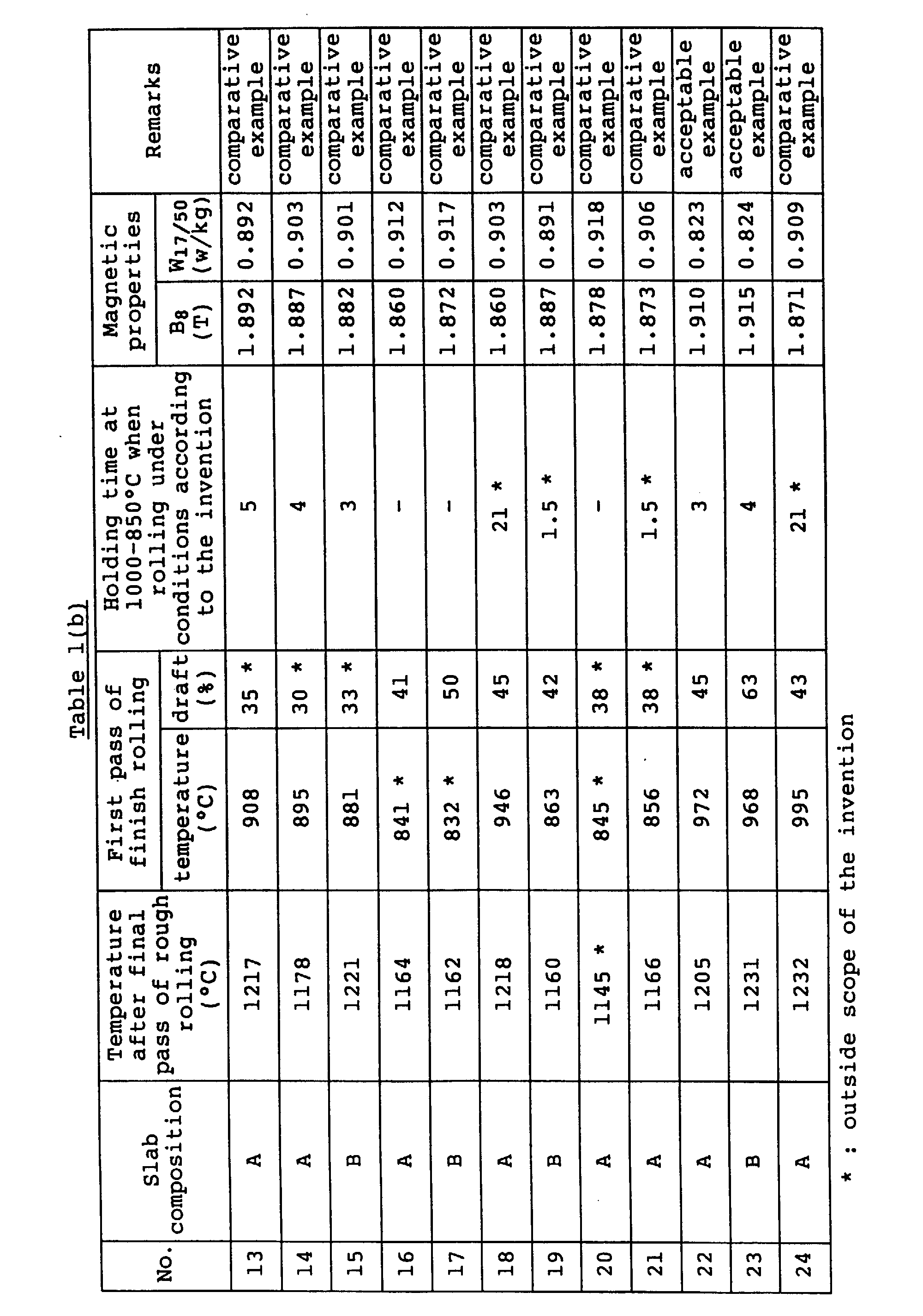
Moreover, the slab used in the invention may be continuously cast slab or a slab obtained by-blooming from an ingot, but naturally includes a slab obtained by blooming and rerolling.
BRIEF DESCRIPTION OF THE DRAWINGS
  • Fig. 1 is a diagram showing the influence of rolling temperature and holding time at this temperature on the precipitation state of an inhibitor;
  • Fig. 2 is a schematic view showing a preferable embodiment of heat hysteresis in accordance with the invention;
  • Fig. 3 is a graph showing the recrystallization limit (recrystallinity of not less than 95%) at single α-phase region as a function of rolling temperature and draft;
  • Fig. 4 is a graph showing the recrystallization limit at (α+β) dual phase region;
  • Fig. 5 is a graph showing the recrystallization limit at single α-phase region after a first pass of the hot rough rolling;
  • Fig. 6 is a graph showing the relation between holding time and recrystallinity after the rolling;
  • Fig. 7 is a graph showing the recrystallization limit at single α-phase region after plural passes of the hot rough rolling;
  • Fig. 8 is a graph showing the change of magnetic flux density in the longitudinal direction of a steel sheet for acceptable examples and comparative examples;
  • Fig. 9 is a graph showing the change of magnetic flux density in the widthwise direction of a steel sheet for acceptable examples and comparative examples; and
  • Fig. 10 is a graph showing the change of magnetic flux density in the longitudinal direction of a steel sheet for acceptable examples and comparative examples.
  • BEST MODE OF CARRYING OUT THE INVENTION Example 1
  • (A) Continuously cast slab comprising C: 0.040%, Si: 3.30%, Mn: 0.054%, Se: 0.022%, Sb: 0.024% and the reminder being substantially Fe.
  • (B) Continuously cast slab comprising C: 0.035%, Si: 2.98%, Mn: 0.072%, Se: 0.024%, Al: 0.023%, N: 0.008% and the reminder being substantially Fe.
  • Each of the above slabs (A) and (B) was placed in a heating furnace, soaked in N2 atmosphere and subjected to rough rolling immediately after the soaking. The rough rolling was carried out through 5-6 passes in accordance with the slab thickness under such a condition that the draft at each pass was approximately equal, whereby a sheet bar of 30 mm in thickness was obtained. Then, the sheet bar was hot rolled in a tandem mill to obtain a hot rolled steel sheet of 2.0 mm in thickness. The temperature after the final pass of the rough rolling and conditions in first pass of the finish rolling are shown in Table 1.
    The hot rolled steel sheet was pickled, subjected to first cold rolling and intermediate annealing and further to second cold rolling to obtain a cold rolled steel sheet having a final thickness of 0.23 mm. Thereafter, the cold rolled steel sheet was subjected to decarburization annealing, coated with a slurry of an annealing separator consisting mainly of MgO, and then subjected to a final finish annealing comprised of secondary recrystallization annealing and purification annealing to obtain a product.
    The magnetic properties of the thus obtained product were measured to obtain results as shown in Table 1.
    Furthermore, the scattering of the magnetic properties in longitudinal direction and widthwise direction was measured to obtain results as shown in Figs. 8 and 9.
    Figure 00360001
    Figure 00370001
    As seen from Table 1 and Figs. 8 and 9, when the first pass in the finish rolling is carried out at a temperature of 1000-850°C and a draft of not less than 40% and this temperature is held for 2-20 seconds, not only the magnetic properties are excellent, but also the uniformity of the magnetic properties in the widthwise direction and longitudinal direction is excellent.
    Example 2
  • (C) Continuously cast slab comprising C: 0.040%, Si: 3.14%, Mn: 0.054%, Se: 0.023%, Sb: 0.024%, Mo: 0.020% and the reminder being substantially Fe.
  • (D) Continuously cast slab comprising C: 0.039%, Si: 3.30%, Mn: 0.054%, Se: 0.019%, Sn: 0.082% and the reminder being substantially Fe.
  • (E) Continuously cast slab comprising C: 0.040%, Si: 3.30%, Mn: 0.054%, Se: 0.022%, Sb: 0.024%, As: 0.020% and the reminder being substantially Fe.
  • (F) Continuously cast slab comprising C: 0.040%, Si: 3.30%, Mn: 0.054%, Se: 0.022%, Sb: 0.024%, Cu: 0.04% and the reminder being substantially Fe.
  • (G) Continuously cast slab comprising C: 0.040%, Si: 3.30%, Mn: 0.054%, Se: 0.022%, Sb: 0.024%, Bi: 0.02% and the reminder being substantially Fe.
  • (H) Continuously cast slab comprising C: 0.040%, Si: 3.30%, Mn: 0.054%, Se: 0.022% and the reminder being substantially Fe.
  • (I) Continuously cast slab comprising C: 0.036%, Si: 3.01%, Mn: 0.069%, Se: 0.023%, Sb: 0.020%, Al: 0.021%, N: 0.008% and the reminder being substantially Fe.
  • Each of the above slabs was placed in a heating furnace, soaked in an N2 atmosphere, and then subjected to a rough rolling just after the soaking. The rough rolling was carried out through 5-6 passes in accordance with the slab thickness under such a condition that the draft at each pass was approximately equal, whereby a sheet bar of 30 mm in thickness was obtained. Then, the sheet bar was hot rolled in a tandem mill to obtain a hot rolled steel sheet of 2.0 mm in thickness. The temperature after the final pass of the rough rolling and conditions in first pass of the finish rolling are shown in Table 2.
    The hot rolled steel sheet was pickled, subjected to first cold rolling and intermediate annealing and further to second cold rolling to obtain a cold rolled steel sheet having a final thickness of 0.23 mm. Thereafter, the cold rolled steel sheet was subjected to decarburization annealing, coated with a slurry of an annealing separator consisting mainly of MgO, and then subjected to a final finish annealing comprised of secondary recrystallization annealing and purification annealing to obtain a product.
    The magnetic properties of the thus obtained product were measured to obtain results as shown in Table 2. In any slab compositions, the products obtained according to the invention are excellent as compared with the comparative examples.
    Figure 00410001
    Example 3
  • (J) Continuously cast slab comprising C: 0.040%, Si: 3.14%, Mn: 0.054%, Se: 0.023%, Sb: 0.024%, Al: 0.022%, N: 0.008%, Mo: 0.020% and the reminder being substantially Fe.
  • (K) Continuously cast slab comprising C: 0.039%, Si: 3.30%, Mn: 0.054%, Se: 0.019%, Sb: 0.022%, Al: 0.023%, N: 0.008%, Sn: 0.080% and the reminder being substantially Fe.
  • (L) Continuously cast slab comprising C: 0.039%, Si: 3.29%, Mn: 0.053%, Se: 0.020%, Sb: 0.023%, Al: 0.020%, N: 0.009%, As: 0.020% and the reminder being substantially Fe.
  • (M) Continuously cast slab comprising C: 0.040%, Si: 3.29%, Mn: 0.054%, Se: 0.021%, Sb: 0.024%, Al: 0.022%, N: 0.008%, Cu: 0.04% and the reminder being substantially Fe.
  • (N) Continuously cast slab comprising C: 0.038%, Si: 3.31%, Mn: 0.054%, Se: 0.022%, Sb: 0.024%, Al: 0.024%, N: 0.008%, Bi: 0.02% and the reminder being substantially Fe.
  • Each of the above slabs was placed in a heating furnace, soaked in an N2 atmosphere, and then subjected to a rough rolling just after the soaking. The rough rolling was carried out through 5-6 passes in accordance with the slab thickness under such a condition that the draft at each pass was approximately equal, whereby a sheet bar of 30 mm in thickness was obtained. Then, the sheet bar was hot rolled in a tandem mill to obtain a hot rolled steel sheet of 2.0 mm in thickness. The temperature after the final pass of the rough rolling and conditions in first pass of the finish rolling are shown in Table 3.
    The hot rolled steel sheet was pickled, subjected to first cold rolling and intermediate annealing and further to second cold rolling to obtain a cold rolled steel sheet having a final thickness of 0.23 mm. Thereafter, the cold rolled steel sheet was subjected to decarburization annealing, coated with a slurry of an annealing separator consisting mainly of MgO, and then subjected to a final finish annealing comprised of secondary recrystallization annealing and purification annealing to obtain a product.
    The magnetic properties of the thus obtained product were measured to obtain results as shown in Table 3. In any slab compositions, the products obtained according to the invention are excellent as compared with the comparative examples.
    Figure 00440001
    Example 4
  • (O) Continuously cast slab comprising C: 0.041%, Si: 3.10%, Mn: 0.074%, Se: 0.021% and the reminder being substantially Fe.
  • (P) Continuously cast slab comprising C: 0.040%, Si: 3.29%, Mn: 0.064%, Se: 0.020%, Sb: 0.024% and the reminder being substantially Fe.
  • (Q) Continuously cast slab comprising C: 0.035%, Si: 3.00%, Mn: 0.072%, Se: 0.023%, Al: 0.023%, N: 0.008% and the reminder being substantially Fe.
  • Each of the above slabs was immediately placed in a gas heating furnace, soaked in an N2 atmosphere, further placed into an induction heating furnace, at where a temperature difference between temperature of central portion being 1430°C and temperature of surface portion being 1370°C was sufficiently ensured, and immediately subjected to a rough rolling. The rough rolling was carried out through 5-6 passes in accordance with the slab thickness under such a condition that the draft at each pass was approximately equal, whereby a sheet bar of 40 mm in thickness was obtained. Moreover, the surface was positively cooled during the rough rolling. Then, the sheet bar was hot rolled in a tandem mill to obtain a hot rolled steel sheet of 3.0 mm in thickness. In this case, the surface of the sheet bar was sufficiently cooled with a high pressure water prior to the finish rolling. The conditions of the finish rolling are shown in Table 4.
    The hot rolled steel sheet was pickled, subjected to first cold rolling and intermediate annealing and further to second cold rolling to obtain a cold rolled steel sheet having a final thickness of 0.23 mm. Thereafter, the cold rolled steel sheet was subjected to decarburization annealing, coated with a slurry of an annealing separator consisting mainly of MgO, and then subjected to a final finish annealing comprised of secondary recrystallization annealing and purification annealing to obtain a product.
    The magnetic properties of the thus obtained product were measured to obtain results as shown in Table 4.
    Figure 00470001
    Figure 00480001
    As seen from Table 4, when the first pass of the finish rolling is carried out under conditions that the draft is not less than 40% at the temperature of the 1/20 layer of 1000°C-950°C and this temperature is held for 3-20 seconds and further the working strain at a draft of not less than 40% is applied at the temperature of the central portion of 950°C-850°C and this temperature is held for 2-20 seconds, the improved magnetic properties are stably obtained.
    In Table 4 is also shown a case using no induction heating furnace. In this case, it is very difficult to take the temperature difference and the temperature difference between the surface layer and the central portion hardly ensures, so that the properties are not stably obtained.
    Example 5
    A continuously cast slab comprising C: 0.043%, Si: 3.08%, Mn: 0.070%, Se: 0.022%, Sb: 0.020% and the reminder being substantially Fe was immediately placed in a gas heating furnace, soaked in an N2 atmosphere to render the temperature of central portion into 1370°C and the temperature of surface portion into 1410°C, and immediately subjected to a rough rolling. The rough rolling was carried out through 5-6 passes in accordance with the slab thickness under such a condition that the draft at each pass was approximately equal, whereby a sheet bar of 30 mm in thickness was obtained. Then, the sheet bar was hot rolled in a tandem mill to obtain a hot rolled steel sheet of 2.0 mm in thickness. The conditions of the finish rolling are shown in Table 5.
    On the other hand, each continuously cast slab having the above composition was immediately placed in a gas heating furnace, soaked in an N2 atmosphere, further placed into an induction heating furnace, at where a temperature difference between temperature of central portion being 1430°C and temperature of surface portion being 1370°C was sufficiently ensured, and immediately subjected to a rough rolling. The rough rolling was carried out under the same conditions as described above, whereby a sheet bar of 40 mm in thickness was obtained. Moreover, the surface was positively cooled during the rough rolling. Then, the sheet bar was hot rolled in a tandem mill to obtain a hot rolled steel sheet of 2.0 mm in thickness. The conditions of the finish rolling are shown in Table 5.
    The hot rolled steel sheet was pickled, subjected to first cold rolling and intermediate annealing and further to second cold rolling to obtain a cold rolled steel sheet having a final thickness of 0.23 mm. Thereafter, the cold rolled steel sheet was subjected to decarburization annealing, coated with a slurry of an annealing separator consisting mainly of MgO, and then subjected to a final finish annealing comprised of secondary recrystallization annealing and purification annealing to obtain a product.
    The magnetic properties of the thus obtained product were measured to obtain results as shown in Table 5.
    In Table 5 are also shown results measured on a case that the temperature of the decarburization annealing at the above steps is shifted to 20°C higher than the optimum temperature.
    From this table, it is understood that when the inhibitor in the hot rolled sheet is controlled at the direction of sheet thickness, the magnetic properties can stably be improved even in the change of treating conditions frequently generated in the actual running line.
    Figure 00520001
    Example 6
    A continuously cast slab comprising C: 0.040%, Si: 3.30%, Mn: 0.054%, Se: 0.022%, Sb: 0.024% and the reminder being substantially Fe was placed into a heating furnace, soaked in an N2 atmosphere, and subjected to a rough rolling under conditions as shown in Table 6 immediately after the soaking, whereby a sheet bar of 30 mm in thickness was obtained.
    Then, the sheet bar was hot rolled in a tandem mill to obtain a hot rolled steel sheet of 2.0 mm in thickness. The hot rolled steel sheet was pickled and subjected to first cold rolling - intermediate annealing -second cold rolling to obtain a cold rolled steel sheet having a final thickness of 0.23 mm. Thereafter, the sheet was subjected to decarburization annealing, coated with a slurry of an annealing separator consisting mainly of MgO, and subjected to a final finish annealing comprised of secondary recrystallization annealing and purification annealing to obtain a product.
    The magnetic properties, surface properties and ratio of poor secondary recrystallized portion in widthwise direction of the thus obtained product were measured to obtain results shown in Table 6.
    Furthermore, results measured on the scattering of magnetic flux density in the longitudinal direction of the steel sheet are shown in Fig. 10.
    Figure 00540001
    Figure 00550001
    As seen from Table 6 and Fig. 10, when the rough rolling is carried out at a high temperature and a large draft according to the invention, the secondary recrystallization uniformly proceeds in the widthwise direction to provide improved magnetic properties, and also the surface properties are good and further the uniformity of the magnetic properties in the longitudinal direction is excellent.
    Example 7
    A continuously cast slab comprising C: 0.035%, Si: 2.98%, Mn: 0.072%, S: 0.018% and the reminder being substantially Fe was placed into a heating furnace, soaked in an N2 atmosphere, and subjected to a rough rolling under conditions as shown in Table 7 immediately after the soaking, whereby a sheet bar of 35 mm in thickness was obtained.
    Then, the sheet bar was hot rolled in a tandem mill to obtain a hot rolled steel sheet of 2.4 mm in thickness. The hot rolled steel sheet was pickled and subjected to first cold rolling - intermediate annealing - second cold rolling to obtain a cold rolled steel sheet having a final thickness of 0.35 mm. Thereafter, the sheet was subjected to decarburization annealing, coated with a slurry of an annealing separator consisting mainly of MgO, and subjected to a final finish annealing comprised of secondary recrystallization annealing and purification annealing to obtain a product.
    The magnetic properties, surface properties and ratio of poor secondary recrystallized portion in widthwise direction of the thus obtained product were measured to obtain results shown in Table 7.
    Figure 00580001
    As seen from Table 7, when the rough rolling is carried out at a high temperature and a large draft according to the invention, the secondary recrystallization uniformly proceeds in the widthwise direction to provide improved magnetic properties, and also the surface properties are good and further the uniformity of the magnetic properties in the longitudinal direction is excellent.
    Example 8
    A continuously cast slab comprising C: 0.050%, Si: 3.10%, Mn: 0.078%, S: 0.024%, Al: 0.032%, N: 0.006% and the reminder being substantially Fe was placed into a heating furnace, soaked in an N2 atmosphere, and subjected to a rough rolling under conditions as shown in Table 6 immediately after the soaking, whereby a sheet bar of 30 mm in thickness was obtained.
    Then, the sheet bar was hot rolled in a tandem mill to obtain a hot rolled steel sheet of 2.3 mm in thickness. The hot rolled steel sheet was pickled and subjected to first cold rolling - intermediate annealing - second cold rolling to obtain a cold rolled steel sheet having a final thickness of 0.23 mm. Thereafter, the sheet was subjected to decarburization annealing, coated with a slurry of an annealing separator consisting mainly of MgO, and subjected to a final finish annealing comprised of secondary recrystallization annealing and purification annealing to obtain a product.
    The magnetic properties, surface properties and ratio of poor secondary recrystallized portion in widthwise direction of the thus obtained product were measured to obtain results shown in Table 8.
    Figure 00610001
    As seen from Table 8, when the rough rolling is carried out at a high temperature and a large draft according to the invention, the secondary recrystallization uniformly proceeds in the widthwise direction to provide improved magnetic properties, and also the surface properties are good and further the uniformity of the magnetic properties in the longitudinal direction is excellent.
    (Example) Example 9
  • (a) Continuously cast slab comprising C: 0.042%, Si: 3.34%, Mn: 0.062%, Se: 0.021%, Sb: 0.025% and the reminder being substantially Fe.
  • (b) Continuously cast slab comprising C: 0.052%, Si: 3.04%, Mn: 0.070%, Se: 0.023%, Al: 0.025%, N: 0.0077% and the reminder being substantially Fe.
  • Each of the above slabs was placed in a heating furnace, soaked in an N2 atmosphere, and immediately subjected to a rough rolling to obtain a sheet bar of 30 mm in thickness, which was hot rolled in a tandem mill to obtain a hot rolled steel sheet of 2.0 mm in thickness. The rough rolling conditions and conditions of first pass in the finish rolling are shown in Table 9.
    The hot rolled steel sheet was pickled and subjected to first cold rolling and intermediate annealing and further to second cold rolling to obtain a cold rolled steel sheet having a final thickness of 0.23 mm. The sheet was subjected to decarburization annealing, coated with a slurry of an annealing separator consisting mainly of MgO, and subjected to final finish annealing comprised of secondary recrystallization annealing and purification annealing to obtain a product.
    The magnetic properties, surface properties and ratio of poor secondary recrystallized portion in widthwise direction of the thus obtained product were measured to obtain results shown in Table 9.
    Figure 00640001
    Figure 00650001
    Figure 00660001
    Figure 00670001
    As seen from the above Table, when the rough rolling and the finish rolling are carried out according to the invention, the magnetic properties and the surface properties are excellent.
    Example 10
  • (c) Continuously cast slab comprising C: 0.041%, Si: 3.18%, Mn: 0.058%, Se: 0.022%, Sb: 0.023%, Mo: 0.020% and the reminder being substantially Fe.
  • (d) Continuously cast slab comprising C: 0.040%, Si: 3.32%, Mn: 0.056%, Se: 0.020%, Sn: 0.081% and the reminder being substantially Fe.
  • (e) Continuously cast slab comprising C: 0.041%, Si: 3.33%, Mn: 0.058%, Se: 0.021%, Sb: 0.025%, As: 0.019% and the reminder being substantially Fe.
  • (f) Continuously cast slab comprising C: 0.042%, Si: 3.28%, Mn: 0.055%, Se: 0.023%, Sb: 0.025%, Cu: 0.05% and the reminder being substantially Fe.
  • (g) Continuously cast slab comprising C: 0.039%, Si: 3.33%, Mn: 0.059%, Se: 0.021%, Sb: 0.023%, Bi: 0.03% and the reminder being substantially Fe.
  • (h) Continuously cast slab comprising C: 0.041%, Si: 3.35%, Mn: 0.060%, Se: 0.024% and the reminder being substantially Fe.
  • (i) Continuously cast slab comprising C: 0.038%, Si: 3.08%, Mn: 0.067%, Se: 0.024%, Sb: 0.024%, Al: 0.022%, N: 0.007% and the reminder being substantially Fe.
  • (j) Continuously cast slab comprising C: 0.041%, Si: 3.17%, Mn: 0.059%, Se: 0.022%, Sb: 0.025%, Al: 0.024%, N: 0.007%, Mo: 0.023% and the reminder being substantially Fe.
  • (k) Continuously cast slab comprising C: 0.040%, Si: 3.35%, Mn: 0.061%, Se: 0.020%, Sb: 0.023%, Al: 0.021%, N: 0.007%, Sn: 0.084% and the reminder being substantially Fe.
  • (l) Continuously cast slab comprising C: 0.041%, Si: 3.34%, Mn: 0.058%, Se: 0.022%, Sb: 0.025%, Al: 0.023%, N: 0.008%, As: 0.023% and the reminder being substantially Fe.
  • (m) Continuously cast slab comprising C: 0.039%, Si: 3.35%, Mn: 0.062%, Se: 0.023%, Sb: 0.023%, Al: 0.021%, N: 0.009%, Cu: 0.05% and the reminder being substantially Fe.
  • (n) Continuously cast slab comprising C: 0.040%, Si: 3.37%, Mn: 0.052%, Se: 0.020%, Sb: 0.026%, Al: 0.027%, N: 0.007%, Bi: 0.03% and the reminder being substantially Fe.
  • Each of the above slabs was placed in a heating furnace, soaked in an N2 atmosphere, and immediately subjected to a rough rolling to obtain a sheet bar of 30 mm in thickness, which was hot rolled in a tandem mill to obtain a hot rolled steel sheet of 2.0 mm in thickness. The rough rolling conditions and conditions of first pass in the finish rolling are shown in Table 10.
    The hot rolled steel sheet was pickled and subjected to first cold rolling and intermediate annealing and further to second cold rolling to obtain a cold rolled steel sheet having a final thickness of 0.23 mm. The sheet was subjected to decarburization annealing, coated with a slurry of an annealing separator consisting mainly of MgO, and subjected to final finish annealing comprised of secondary recrystallization annealing and purification annealing to obtain a product.
    The magnetic properties, surface properties and ratio of poor secondary recrystallized portion in widthwise direction of the thus obtained product were measured to obtain results shown in Table 10. In any slab compositions, the products obtained according to the invention are excellent as compared with the comparative examples.
    Figure 00710001
    Figure 00720001
    Figure 00730001
    Figure 00740001
    Example 11
    A continuously cast slab comprising C: 0.034%, Si: 3.01%, Mn: 0.070%, S: 0.017% and the reminder being substantially Fe was placed in a heating furnace, soaked in an N2 atmosphere, and subjected to a rough rolling under conditions shown in Table 11 immediately after the soaking, whereby a sheet bar of 35 mm in thickness was obtained. Thereafter, the sheet bar was subjected to a finish tandem rolling under conditions shown in the same Table 11 to obtain a hot rolled steel sheet of 2.4 mm in thickness.
    The hot rolled steel sheet was pickled and subjected to first cold rolling - intermediate annealing - second cold rolling to obtain a cold rolled sheet of 0.35 mm in thickness. Then, the sheet was subjected to decarburization annealing, coated with MgO, and subjected to a final finish annealing comprised of secondary recrystallization annealing and purification annealing to obtain a product.
    The magnetic properties, surface properties and ratio of poor secondary recrystallized portion in widthwise direction of the thus obtained product were measured to obtain results shown in Table 11.
    Figure 00760001
    Figure 00770001
    As seen from the above Table, when the rough rolling and the finish rolling are carried out according to the invention, not only the magnetic properties and surface properties but also the uniformity of the magnetic properties in the longitudinal direction are excellent.
    Example 12
  • (i) Continuously cast slab comprising C: 0.038%, Si: 3.20%, Mn: 0.070%, Se: 0.021% and the reminder being substantially Fe.
  • (ii) Continuously cast slab comprising C: 0.041%, Si: 3.28%, Mn: 0.065%, Se: 0.017%, Sb: 0.023% and the reminder being substantially Fe.
  • (iii) Continuously cast slab comprising C: 0.036%, Si: 3.11%, Mn: 0.071%, Se: 0.022%, Al: 0.022%, N: 0.008% and the reminder being substantially Fe.
  • Each of the above slabs was immediately placed in a gas heating furnace, soaked in an N2 atmosphere, further placed into an induction heating furnace, at where a temperature difference between temperature of central portion being 1430°C and temperature of surface portion being 1370°C was sufficiently ensured, and immediately subjected to a rough rolling under conditions shown in Table 12, whereby a sheet bar of 30 mm in thickness was obtained. Moreover, the surface was positively cooled during the rough rolling. Then, the sheet bar was subjected to a finish tandem rolling under conditions shown in the same Table 12 to obtain a hot rolled steel sheet of 2.7 mm in thickness. Prior to the finish rolling, the surface of the sheet bar was sufficiently cooled with a high pressure water.
    The hot rolled steel sheet was pickled, subjected to first cold rolling and intermediate annealing and further to second cold rolling to obtain a cold rolled steel sheet having a final thickness of 0.27 mm. Thereafter, the cold rolled steel sheet was subjected to decarburization annealing, coated with a slurry of an annealing separator consisting mainly of MgO, and then subjected to a final finish annealing comprised of secondary recrystallization annealing and purification annealing to obtain a product.
    The magnetic properties of the thus obtained product were measured to obtain results as shown in Table 12.
    Figure 00800001
    Figure 00810001
    As seen from Table 12, when the rough rolling is carried out at a high temperature and a large draft and then the first pass of the finish rolling is carried out under such conditions that the draft is not less than 40% at the temperature of the 1/20 layer of 1000°C-950°C and this temperature is held for 3-20 seconds and further the working strain at a draft of not less than 40% is applied at the temperature of the central portion of 950°C-850°C and this temperature is held for 2-20 seconds, the improved magnetic properties are stably obtained.
    In Table 12 is also shown a case using no induction heating furnace. In this case, it is very difficult to take the temperature difference and the temperature difference between the surface layer and the central portion hardly ensures, so that the properties become not stable.
    Example 13
    A continuously cast slab comprising C: 0.043%, Si: 3.41%, Mn: 0.072%, Se: 0.020%, Sb: 0.020% and the reminder being substantially Fe was immediately placed in a gas heating furnace, soaked in an N2 atmosphere render the temperature of central portion into 1370°C and the temperature of surface layer portion into 1410°C, and immediately subjected to a rough rolling under conditions shown in Table 13, whereby a sheet bar of 30 mm in thickness was obtained. Then, the sheet bar was subjected to a finish tandem rolling under conditions shown in Table 13 to obtain a hot rolled steel sheet of 2.0 mm in thickness.
    On the other hand, the continuously cast slab having the above composition was immediately placed in a gas heating furnace, soaked in an N2 atmosphere, further placed into an induction heating furnace, at where a temperature difference between temperature of central portion being 1430°C and temperature of surface portion being 1370°C was sufficiently ensured, and subjected to a rough rolling and finish rolling under conditions shown in Table 13, whereby a hot rolled steel sheet of 2.0 mm in thickness was obtained. Moreover, the surface was positively cooled during the rough rolling.
    These hot rolled steel sheets were pickled, subjected to first cold rolling and intermediate annealing and further to second cold rolling to obtain a cold rolled steel sheet having a final thickness of 0.23 mm. Thereafter, the cold rolled steel sheets were subjected to decarburization diannealing, coated with a slurry of an annealing separator consisting mainly of MgO, and then subjected to a final finish annealing comprised of secondary recrystallization annealing and purification annealing to obtain products.
    The magnetic properties of the thus obtained products were measured to obtain results as shown in Table 13.
    In Table 13 are also shown results measured on a case that the temperature of the decarburization annealing at the above steps is shifted to 20°C higher than the optimum temperature.
    From this table, it is understood that when the inhibitor in the hot rolled sheet is controlled at the direction of sheet thickness, the magnetic properties can stably be improved even in the change of treating conditions frequently generated in the actual running line.
    Figure 00850001
    Figure 00860001
    INDUSTRIAL APPLICABILITY
    According to the invention, grain oriented silicon steel sheets having improved magnetic properties over a whole of the steel sheet and good surface properties can stably be produced.
    Furthermore, according to the invention, the merits of the hot strip mill can be utilized at maximum in the production of the grain oriented silicon steel sheet, so that not only the improvement of the productivity but also the energy-saving can be achieved.

    Claims (4)

    1. A method of producing a grain oriented silicon steel sheet having improved magnetic properties by a series of steps including subjecting a slab of silicon-containing steel to hot rolling comprising rough rolling and subsequent finish rolling after heating, subjecting the hot rolled sheet to a heavy cold rolling or to cold rolling twice with an intermediate annealing to a final sheet thickness, subjecting the cold rolled sheet to decarburization annealing, applying a slurry of an annealing separator to a surface of the decarburised steel sheet, and subjecting the thus treated sheet to a final finish annealing, whereby in the hot rolling step, said rough rolling is carried out in a temperature region exceeding 1150°C and at least one pass of said finish rolling is carried out while holding the temperature in a central portion of the steel sheet in the thickness direction above 1150°C and said finish rolling pass is carried out at a draft of not less than 40% when the temperature in a surface layer corresponding to 1/20 of the sheet thickness reaches a temperature range of 1000-950°C and said temperature range is held for 3-20 seconds.
    2. A method according to claim 1, wherein said rough rolling is carried out in such a manner that a first pass is carried out under conditions that the rolling temperature T1 is not lower than 1280°C and the draft R1 satisfies the following equation: 60 ≥ R1 (%) ≥ -0.5T1 + 670 and the above conditions are held for not less than 30 seconds, and a final pass is carried out under conditions that the rolling temperature T2 is not lower than 1200°C and the draft R2 satisfies the following equation: 70 ≥ R2 (%) ≥ -0.1T2 + 165.
    3. A method according to claim 1 or 2, wherein said finish rolling is carried out in such a manner that said steel sheet is cooled while holding the temperature in a central portion of said steel sheet in the thickness direction above 1150°C and, when the temperature at a position below the surface of the sheet corresponding to 1/20th of the sheet thickness reaches a temperature range of 1000-950°C, the steel sheet is rolled at a draft of not less than 40% and held at the above temperature range for 3-20 seconds and then cooled and, when the temperature at the central portion reaches a temperature range of 950-850°C, the steel sheet is rolled at a draft of not less than 40% and held at this temperature range for 2-20 seconds.
    4. A method according to any one of claims 1 to 3, wherein the slab is heated so that the temperature of the central portion of the slab is not lower than 1370°C.
    EP90907406A 1989-05-08 1990-05-08 Process for manufacturing unidirectional silicon steel sheet excellent in magnetic properties Expired - Lifetime EP0426869B1 (en)

    Applications Claiming Priority (7)

    Application Number Priority Date Filing Date Title
    JP11364389A JPH0310020A (en) 1989-05-08 1989-05-08 Production of grain-oriented silicon steel sheet excellent in magnetic property and surface characteristic
    JP113643/89 1989-05-08
    JP12033789 1989-05-16
    JP120337/89 1989-05-16
    JP25526089 1989-10-02
    JP255260/89 1989-10-02
    PCT/JP1990/000586 WO1990013673A1 (en) 1989-05-08 1990-05-08 Process for manufacturing unidirectional silicon steel sheet excellent in magnetic properties

    Publications (3)

    Publication Number Publication Date
    EP0426869A1 EP0426869A1 (en) 1991-05-15
    EP0426869A4 EP0426869A4 (en) 1994-04-06
    EP0426869B1 true EP0426869B1 (en) 1998-08-12

    Family

    ID=27312552

    Family Applications (1)

    Application Number Title Priority Date Filing Date
    EP90907406A Expired - Lifetime EP0426869B1 (en) 1989-05-08 1990-05-08 Process for manufacturing unidirectional silicon steel sheet excellent in magnetic properties

    Country Status (6)

    Country Link
    US (1) US5296050A (en)
    EP (1) EP0426869B1 (en)
    KR (1) KR0169734B1 (en)
    CA (1) CA2032502C (en)
    DE (1) DE69032553T2 (en)
    WO (1) WO1990013673A1 (en)

    Families Citing this family (11)

    * Cited by examiner, † Cited by third party
    Publication number Priority date Publication date Assignee Title
    KR930004849B1 (en) † 1991-07-12 1993-06-09 포항종합제철 주식회사 Electrcal steel sheet having a good magnetic property and its making process
    DE4236307A1 (en) † 1992-10-28 1994-05-05 Schloemann Siemag Ag Method and plant for the production of hot-rolled steel strip, in particular from strip-shaped continuous material
    US5572892A (en) * 1992-12-28 1996-11-12 Kawasaki Steel Corporation Method of producing silicon steel hot rolled sheets having excellent surface properties
    JP3227057B2 (en) 1994-06-27 2001-11-12 川崎製鉄株式会社 Method for producing hot rolled silicon steel sheet with excellent surface properties
    US5710411A (en) * 1995-08-31 1998-01-20 Tippins Incorporated Induction heating in a hot reversing mill for isothermally rolling strip product
    IT1402624B1 (en) * 2009-12-23 2013-09-13 Ct Sviluppo Materiali Spa PROCEDURE FOR THE PRODUCTION OF MAGNETIC SIDES WITH ORIENTED GRAIN.
    IN2014MN01830A (en) * 2012-03-29 2015-07-03 Jfe Steel Corp
    KR102538120B1 (en) * 2020-12-21 2023-05-26 주식회사 포스코 Grain oriented electrical steel sheet and method for manufacturing the same
    WO2022163723A1 (en) * 2021-01-28 2022-08-04 Jfeスチール株式会社 Method for manufacturing oriented electromagnetic steel sheet and rolling equipment for manufacturing electromagnetic steel sheet
    CN117545862A (en) * 2021-06-30 2024-02-09 杰富意钢铁株式会社 Method for producing oriented electrical steel sheet and rolling facility for producing oriented electrical steel sheet
    EP4353850A4 (en) * 2021-06-30 2025-07-30 Jfe Steel Corp Method for producing an oriented electromagnetic steel sheet and rolling equipment for producing an oriented electromagnetic steel sheet

    Family Cites Families (17)

    * Cited by examiner, † Cited by third party
    Publication number Priority date Publication date Assignee Title
    US2867557A (en) * 1956-08-02 1959-01-06 Allegheny Ludlum Steel Method of producing silicon steel strip
    JPS54118326A (en) * 1978-03-07 1979-09-13 Kawasaki Steel Co Production of one directional steel plate with excellent magnetic property
    JPS6037172B2 (en) * 1978-03-11 1985-08-24 新日本製鐵株式会社 Manufacturing method of unidirectional silicon steel sheet
    US4204891A (en) * 1978-11-27 1980-05-27 Nippon Steel Corporation Method for preventing the edge crack in a grain oriented silicon steel sheet produced from a continuously cast steel slab
    JPS55119216A (en) 1979-03-06 1980-09-12 Nissan Motor Co Ltd Low noise engine
    JPS5711614A (en) 1980-06-26 1982-01-21 Toyo Boseki Bedding
    JPS597768B2 (en) * 1981-05-30 1984-02-21 新日本製鐵株式会社 Manufacturing method of unidirectional electrical steel sheet with excellent magnetic properties
    JPS5813606A (en) 1981-07-17 1983-01-26 Nippon Ii P Rubber Kk Preparation of olefin copolymer rubber
    US4473416A (en) * 1982-07-08 1984-09-25 Nippon Steel Corporation Process for producing aluminum-bearing grain-oriented silicon steel strip
    JPH0232327B2 (en) 1982-11-17 1990-07-19 Kawasaki Steel Co HOKOSEIKEISOKOHANYOSURABUNONETSUKANATSUENHOHO
    JPS59193216A (en) 1983-04-15 1984-11-01 Kawasaki Steel Corp Preparation of orientated silicon steel plate
    JPS6112822A (en) * 1984-06-29 1986-01-21 Nippon Steel Corp Manufacture of grain oriented electrical sheet having low iron loss
    JPS6184327A (en) * 1984-09-29 1986-04-28 Nippon Steel Corp Production of high-silicon thin grain-oriented silicon steel sheet
    JPS62103321A (en) * 1985-06-14 1987-05-13 Nippon Kokan Kk <Nkk> Manufacture of silicon steel sheet having superior soft magnetic characteristic
    JP2524118B2 (en) 1986-07-02 1996-08-14 富士通テン株式会社 Control circuit for electronic tuning tuner
    JPH0753885B2 (en) * 1989-04-17 1995-06-07 新日本製鐵株式会社 Method for producing unidirectional electrical steel sheet with excellent magnetic properties
    JP3219213B2 (en) * 1992-09-30 2001-10-15 ソニー株式会社 Analog digital conversion circuit

    Also Published As

    Publication number Publication date
    DE69032553T2 (en) 1999-03-11
    WO1990013673A1 (en) 1990-11-15
    CA2032502C (en) 1997-10-14
    US5296050A (en) 1994-03-22
    EP0426869A4 (en) 1994-04-06
    KR920701491A (en) 1992-08-11
    DE69032553D1 (en) 1998-09-17
    CA2032502A1 (en) 1990-11-09
    EP0426869A1 (en) 1991-05-15
    KR0169734B1 (en) 1999-01-15

    Similar Documents

    Publication Publication Date Title
    EP3960887B1 (en) Method for producing grain-oriented electrical steel sheet
    WO2006132095A1 (en) Grain-oriented magnetic steel sheet with extremely high magnetic property and process for producing the same
    US5009726A (en) Method of making non-oriented silicon steel sheets having excellent magnetic properties
    US5296050A (en) Method of producing grain oriented silicon steel sheets having improved magnetic properties
    CN113825847A (en) Method for producing grain-oriented electrical steel sheet
    CN116888286A (en) Manufacturing method of grain-oriented electromagnetic steel plate
    JP2001152250A (en) Manufacturing method of grain-oriented electrical steel sheet with excellent magnetic properties
    EP0019289B1 (en) Process for producing grain-oriented silicon steel strip
    JPH0323607B2 (en)
    JP2872404B2 (en) Method for producing unidirectional silicon steel sheet with excellent magnetic properties
    JP6228956B2 (en) Low iron loss high magnetic flux density grained electrical steel sheet and manufacturing method thereof
    JP2612075B2 (en) Method for producing unidirectional silicon steel sheet with excellent magnetic properties and surface properties
    JP3301622B2 (en) Method for producing grain-oriented silicon steel sheet having uniform and excellent magnetic properties in the sheet width direction
    JP4239276B2 (en) Directional electromagnetic steel hot rolled steel sheet manufacturing method
    JP2612074B2 (en) Method for producing unidirectional silicon steel sheet with excellent magnetic properties and surface properties
    JP3885264B2 (en) Method for producing grain-oriented electrical steel sheet
    JPH03115525A (en) Production of grain-oriented silicon steel sheet excellent in magnetic property
    JPH06328214A (en) How to prevent ferritic stainless steel from cracking
    JP2883224B2 (en) Manufacturing method of grain-oriented electrical steel sheet with excellent magnetic properties
    JPH10259422A (en) Manufacturing method of grain-oriented electrical steel sheet with good iron loss characteristics
    JPH0222422A (en) Production of unidirectional type silicon steel sheet excellent in magnetic property
    JP2574583B2 (en) Method for manufacturing oriented silicon steel sheet with good iron loss
    JPS6210213A (en) Production of grain oriented silicon steel sheet having good electromagnetic characteristic
    JP2726295B2 (en) Method for producing oriented silicon steel sheet with excellent magnetic properties and surface properties
    JPWO1990013673A1 (en) Manufacturing method for grain-oriented silicon steel sheet with excellent magnetic properties

    Legal Events

    Date Code Title Description
    PUAI Public reference made under article 153(3) epc to a published international application that has entered the european phase

    Free format text: ORIGINAL CODE: 0009012

    17P Request for examination filed

    Effective date: 19910104

    AK Designated contracting states

    Kind code of ref document: A1

    Designated state(s): DE FR GB IT SE

    A4 Supplementary search report drawn up and despatched

    Effective date: 19940217

    AK Designated contracting states

    Kind code of ref document: A4

    Designated state(s): DE FR GB IT SE

    17Q First examination report despatched

    Effective date: 19941125

    GRAG Despatch of communication of intention to grant

    Free format text: ORIGINAL CODE: EPIDOS AGRA

    GRAG Despatch of communication of intention to grant

    Free format text: ORIGINAL CODE: EPIDOS AGRA

    GRAH Despatch of communication of intention to grant a patent

    Free format text: ORIGINAL CODE: EPIDOS IGRA

    GRAH Despatch of communication of intention to grant a patent

    Free format text: ORIGINAL CODE: EPIDOS IGRA

    GRAA (expected) grant

    Free format text: ORIGINAL CODE: 0009210

    ITF It: translation for a ep patent filed
    AK Designated contracting states

    Kind code of ref document: B1

    Designated state(s): DE FR GB IT SE

    REF Corresponds to:

    Ref document number: 69032553

    Country of ref document: DE

    Date of ref document: 19980917

    ET Fr: translation filed
    PG25 Lapsed in a contracting state [announced via postgrant information from national office to epo]

    Ref country code: SE

    Free format text: LAPSE BECAUSE OF FAILURE TO SUBMIT A TRANSLATION OF THE DESCRIPTION OR TO PAY THE FEE WITHIN THE PRESCRIBED TIME-LIMIT

    Effective date: 19981112

    PLBE No opposition filed within time limit

    Free format text: ORIGINAL CODE: 0009261

    STAA Information on the status of an ep patent application or granted ep patent

    Free format text: STATUS: NO OPPOSITION FILED WITHIN TIME LIMIT

    26N No opposition filed
    REG Reference to a national code

    Ref country code: GB

    Ref legal event code: IF02

    PGFP Annual fee paid to national office [announced via postgrant information from national office to epo]

    Ref country code: GB

    Payment date: 20040505

    Year of fee payment: 15

    PG25 Lapsed in a contracting state [announced via postgrant information from national office to epo]

    Ref country code: GB

    Free format text: LAPSE BECAUSE OF NON-PAYMENT OF DUE FEES

    Effective date: 20050508

    Ref country code: IT

    Free format text: LAPSE BECAUSE OF NON-PAYMENT OF DUE FEES

    Effective date: 20050508

    GBPC Gb: european patent ceased through non-payment of renewal fee

    Effective date: 20050508

    PGFP Annual fee paid to national office [announced via postgrant information from national office to epo]

    Ref country code: DE

    Payment date: 20090429

    Year of fee payment: 20

    Ref country code: FR

    Payment date: 20090515

    Year of fee payment: 20

    PG25 Lapsed in a contracting state [announced via postgrant information from national office to epo]

    Ref country code: DE

    Free format text: LAPSE BECAUSE OF EXPIRATION OF PROTECTION

    Effective date: 20100508