EP0425985B1 - Stereoskopisches bilderzeugendes System - Google Patents
Stereoskopisches bilderzeugendes System Download PDFInfo
- Publication number
- EP0425985B1 EP0425985B1 EP90120317A EP90120317A EP0425985B1 EP 0425985 B1 EP0425985 B1 EP 0425985B1 EP 90120317 A EP90120317 A EP 90120317A EP 90120317 A EP90120317 A EP 90120317A EP 0425985 B1 EP0425985 B1 EP 0425985B1
- Authority
- EP
- European Patent Office
- Prior art keywords
- image
- distance
- imaging units
- stereoscopic
- lenses
- Prior art date
- Legal status (The legal status is an assumption and is not a legal conclusion. Google has not performed a legal analysis and makes no representation as to the accuracy of the status listed.)
- Expired - Lifetime
Links
- 238000003384 imaging method Methods 0.000 title claims description 66
- 230000003287 optical effect Effects 0.000 claims description 48
- 230000015654 memory Effects 0.000 claims description 13
- 230000003111 delayed effect Effects 0.000 claims description 4
- 230000007246 mechanism Effects 0.000 claims description 4
- 230000002194 synthesizing effect Effects 0.000 claims description 3
- 238000010586 diagram Methods 0.000 description 23
- 238000000034 method Methods 0.000 description 18
- 210000003128 head Anatomy 0.000 description 14
- 230000008859 change Effects 0.000 description 11
- 230000000694 effects Effects 0.000 description 5
- 239000004973 liquid crystal related substance Substances 0.000 description 3
- 230000010363 phase shift Effects 0.000 description 3
- 230000001360 synchronised effect Effects 0.000 description 3
- 230000009471 action Effects 0.000 description 2
- 238000013459 approach Methods 0.000 description 2
- 238000010276 construction Methods 0.000 description 2
- 239000011521 glass Substances 0.000 description 2
- 230000008447 perception Effects 0.000 description 2
- 230000000737 periodic effect Effects 0.000 description 2
- 230000008569 process Effects 0.000 description 2
- 206010019233 Headaches Diseases 0.000 description 1
- 208000003464 asthenopia Diseases 0.000 description 1
- 238000005452 bending Methods 0.000 description 1
- 210000004556 brain Anatomy 0.000 description 1
- 238000006243 chemical reaction Methods 0.000 description 1
- 230000001934 delay Effects 0.000 description 1
- 238000001514 detection method Methods 0.000 description 1
- 238000005516 engineering process Methods 0.000 description 1
- 231100000869 headache Toxicity 0.000 description 1
- 230000007794 irritation Effects 0.000 description 1
- 239000000463 material Substances 0.000 description 1
- 230000010287 polarization Effects 0.000 description 1
- 230000004044 response Effects 0.000 description 1
- 238000001356 surgical procedure Methods 0.000 description 1
Images


Classifications
-
- H—ELECTRICITY
- H04—ELECTRIC COMMUNICATION TECHNIQUE
- H04N—PICTORIAL COMMUNICATION, e.g. TELEVISION
- H04N19/00—Methods or arrangements for coding, decoding, compressing or decompressing digital video signals
- H04N19/50—Methods or arrangements for coding, decoding, compressing or decompressing digital video signals using predictive coding
- H04N19/597—Methods or arrangements for coding, decoding, compressing or decompressing digital video signals using predictive coding specially adapted for multi-view video sequence encoding
-
- H—ELECTRICITY
- H04—ELECTRIC COMMUNICATION TECHNIQUE
- H04N—PICTORIAL COMMUNICATION, e.g. TELEVISION
- H04N13/00—Stereoscopic video systems; Multi-view video systems; Details thereof
- H04N13/10—Processing, recording or transmission of stereoscopic or multi-view image signals
- H04N13/106—Processing image signals
- H04N13/161—Encoding, multiplexing or demultiplexing different image signal components
-
- H—ELECTRICITY
- H04—ELECTRIC COMMUNICATION TECHNIQUE
- H04N—PICTORIAL COMMUNICATION, e.g. TELEVISION
- H04N13/00—Stereoscopic video systems; Multi-view video systems; Details thereof
- H04N13/10—Processing, recording or transmission of stereoscopic or multi-view image signals
- H04N13/106—Processing image signals
- H04N13/167—Synchronising or controlling image signals
-
- H—ELECTRICITY
- H04—ELECTRIC COMMUNICATION TECHNIQUE
- H04N—PICTORIAL COMMUNICATION, e.g. TELEVISION
- H04N13/00—Stereoscopic video systems; Multi-view video systems; Details thereof
- H04N13/10—Processing, recording or transmission of stereoscopic or multi-view image signals
- H04N13/189—Recording image signals; Reproducing recorded image signals
-
- H—ELECTRICITY
- H04—ELECTRIC COMMUNICATION TECHNIQUE
- H04N—PICTORIAL COMMUNICATION, e.g. TELEVISION
- H04N13/00—Stereoscopic video systems; Multi-view video systems; Details thereof
- H04N13/20—Image signal generators
- H04N13/204—Image signal generators using stereoscopic image cameras
- H04N13/239—Image signal generators using stereoscopic image cameras using two 2D image sensors having a relative position equal to or related to the interocular distance
-
- H—ELECTRICITY
- H04—ELECTRIC COMMUNICATION TECHNIQUE
- H04N—PICTORIAL COMMUNICATION, e.g. TELEVISION
- H04N13/00—Stereoscopic video systems; Multi-view video systems; Details thereof
- H04N13/20—Image signal generators
- H04N13/296—Synchronisation thereof; Control thereof
-
- H—ELECTRICITY
- H04—ELECTRIC COMMUNICATION TECHNIQUE
- H04N—PICTORIAL COMMUNICATION, e.g. TELEVISION
- H04N13/00—Stereoscopic video systems; Multi-view video systems; Details thereof
- H04N13/30—Image reproducers
- H04N13/366—Image reproducers using viewer tracking
- H04N13/371—Image reproducers using viewer tracking for tracking viewers with different interocular distances; for tracking rotational head movements around the vertical axis
-
- H—ELECTRICITY
- H04—ELECTRIC COMMUNICATION TECHNIQUE
- H04N—PICTORIAL COMMUNICATION, e.g. TELEVISION
- H04N13/00—Stereoscopic video systems; Multi-view video systems; Details thereof
- H04N13/30—Image reproducers
- H04N13/366—Image reproducers using viewer tracking
- H04N13/373—Image reproducers using viewer tracking for tracking forward-backward translational head movements, i.e. longitudinal movements
-
- H—ELECTRICITY
- H04—ELECTRIC COMMUNICATION TECHNIQUE
- H04N—PICTORIAL COMMUNICATION, e.g. TELEVISION
- H04N13/00—Stereoscopic video systems; Multi-view video systems; Details thereof
- H04N13/30—Image reproducers
- H04N13/366—Image reproducers using viewer tracking
- H04N13/376—Image reproducers using viewer tracking for tracking left-right translational head movements, i.e. lateral movements
-
- H—ELECTRICITY
- H04—ELECTRIC COMMUNICATION TECHNIQUE
- H04N—PICTORIAL COMMUNICATION, e.g. TELEVISION
- H04N13/00—Stereoscopic video systems; Multi-view video systems; Details thereof
- H04N13/30—Image reproducers
- H04N13/366—Image reproducers using viewer tracking
- H04N13/38—Image reproducers using viewer tracking for tracking vertical translational head movements
-
- H—ELECTRICITY
- H04—ELECTRIC COMMUNICATION TECHNIQUE
- H04N—PICTORIAL COMMUNICATION, e.g. TELEVISION
- H04N13/00—Stereoscopic video systems; Multi-view video systems; Details thereof
- H04N13/30—Image reproducers
- H04N13/398—Synchronisation thereof; Control thereof
-
- H—ELECTRICITY
- H04—ELECTRIC COMMUNICATION TECHNIQUE
- H04N—PICTORIAL COMMUNICATION, e.g. TELEVISION
- H04N13/00—Stereoscopic video systems; Multi-view video systems; Details thereof
- H04N13/10—Processing, recording or transmission of stereoscopic or multi-view image signals
-
- H—ELECTRICITY
- H04—ELECTRIC COMMUNICATION TECHNIQUE
- H04N—PICTORIAL COMMUNICATION, e.g. TELEVISION
- H04N13/00—Stereoscopic video systems; Multi-view video systems; Details thereof
- H04N13/10—Processing, recording or transmission of stereoscopic or multi-view image signals
- H04N13/106—Processing image signals
- H04N13/15—Processing image signals for colour aspects of image signals
-
- H—ELECTRICITY
- H04—ELECTRIC COMMUNICATION TECHNIQUE
- H04N—PICTORIAL COMMUNICATION, e.g. TELEVISION
- H04N13/00—Stereoscopic video systems; Multi-view video systems; Details thereof
- H04N13/30—Image reproducers
- H04N13/332—Displays for viewing with the aid of special glasses or head-mounted displays [HMD]
- H04N13/337—Displays for viewing with the aid of special glasses or head-mounted displays [HMD] using polarisation multiplexing
-
- H—ELECTRICITY
- H04—ELECTRIC COMMUNICATION TECHNIQUE
- H04N—PICTORIAL COMMUNICATION, e.g. TELEVISION
- H04N13/00—Stereoscopic video systems; Multi-view video systems; Details thereof
- H04N13/30—Image reproducers
- H04N13/332—Displays for viewing with the aid of special glasses or head-mounted displays [HMD]
- H04N13/341—Displays for viewing with the aid of special glasses or head-mounted displays [HMD] using temporal multiplexing
Definitions
- This invention relates to a stereoscopic imaging system for providing stereoscopic images, and particularly to a stereoscopic imaging system which permits observation of stereoscopic images with less fatigue, without producing an unnatural feeling to the observing eyes and without depending on the position of the observing eyes.
- a stereoscopic (three-dimensional) television system which provides stereoscopic images by generating the above-mentioned factors by means of two television cameras and provides the eyes with the images separately, thereby giving the viewer a perception of viewing the stereoscopic object.
- Figs. 1A, 1B and 1C show an example in which one monitor is used.
- the left camera 1 and the right camera 2 result in images in which there is a binocular parallax.
- a field change-over signal processing unit 3 produces a synthesized video signal 4 made by alternately arranging frames L with frames R from the left and right camera heads 1 and 2.
- An A/D converter 5 converts this video signal into a digital signal which is stored in a frame memory 6, and a frame number converter 7 re-arranges the digital signal as a video signal 8 provided at a speed twice as fast as before.
- a D/A converter 9 converts this video signal 8 (Fig. 1B) in digital form into analog form, and shows the analog video signal on a twice-high-speed scanning monitor 10.
- Liquid crystal glasses 11 open and close liquid crystal shutters synchronized with the frames alternately shown on the twice-high-speed scanning monitor 10 in response to shutter signals 12 and 13 (Fig. 1C) synchronized with the frames produced by the frame number converter 7. Therefore, the left eye sees only the left frames L and the right eye sees only the right frames R.
- a method which, instead of the liquid crystal shutters, uses polarized light shutters, placed in front of the monitor screen or a projection lens of a video projector, operates the polarized light shutters by turns in synchronism with the left and right frames, and the person can separate the left and right images and obtain a stereoscopic image by wearing polarizing glasses using polarizing lenses, the polarizing directions of which differ between the left and right lenses.
- GB-A-2 147 762 shows an artificial binocular vision system in accordance with the preambles of claims 9 and 10 wherein the center of an image-forming plane can be offset from the optical axis of the lens.
- US-A-4 677 468 shows a stereoscopic television display device in which the two TV cameras are inclined and the timing of read out data of a frame memory for right eye and the timing of read out data of a frame memory for left eye are shifted with respect to each other other so that the observer can freely select a point other than a camera's observation point as his observation point.
- a slanted camera arrangement is also shown in GB-A-2 085 692 which likewise relates to a three-dimensional television picture display system and picture pick-up device in which information intended for the right and left eye, respectively of an observer is generated on a display screen in respective first and second images which are shifted into the direction of line scan.
- the periodic line blanking of the second image intended for the left eye is shifted into the direction of line scan at picture generation on the display screen relative to the periodic line blanking of the first image intended for the right eye.
- the three-dimensionally shifted line blanking can be realized either electronically or by providing on either side of the screen of the picture display device strips which transmit information to one eye only of the observer.
- the relative position of the two camera heads 1, 2 is set in the following two ways (Figs. 2 and 6).
- One method is that, as shown in Fig. 2, the two camera heads 1, 2 are arranged with their optical axes oriented in parallel. If an object, from which images are obtained is located in front of the two parallel camera heads 1, 2, the images are formed on image-forming planes 17, 18 by lenses 15, 16.
- the sizes and directions of images l and r on the image-forming planes are indicated by leader lines.
- the two images l and r are displayed alternately on the monitor screen 19 as shown in Fig. 3, and the images are perceived by a person's eyes 20, 21.
- the left eye views the image l seen from the left hand side, while the right eye views the image r seen from the right hand side.
- a synthesized image 22 that can be seen by the binocular parallax is located in front of the monitor screen 19.
- Fig. 2 if the object 14 is moved along the intermediate axis between the two camera heads 1, 2 to a point at infinity, the images of the object are formed at the central points of the left and right image-forming planes 17, 18.
- the point at infinity is located at the center of the monitor screen 19.
- positions k and m of the point p (x,y) on the image-forming planes are expressed by the following equations.
- k d(b/2+x) y
- m d(b/2-x) y
- b the distance between the centers of the image-forming planes 17, 18, d is the distance from each of the lens centers to the image-forming planes, and s is the size of the image-forming planes.
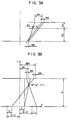
- Another method of setting the relative position of the camera heads 1, 2 is to converge the optical axes of the cameras as shown in Fig. 6.
- the image obtained by this method is expressed by using the arrangements in Figs. 7 and 8.
- the positions k and m of the point p(x,y) on the image-forming planes are expressed as follows.
- both X and Y subject to the effect of x and y, are not in a simple proportional relationship. Therefore, the images taken by the left and right camera heads 1, 2 have an image distortion in addition to a transverse difference between them caused by binocular parallax, thus posing difficulty in obtaining a stereoscopic image.
- a stereoscopic camera is constructed such that normals of the image-forming planes of the two cameras are arranged in parallel, that the distance between the optical centers of lenses of the two cameras is shorter than the distance between the centers of image-forming planes of said two cameras, that both the ratio of the distance which remains after subtraction of the lenses spacing from the image-forming planes spacing to the distance between the eyes of the observer and the ratio of the distance from the image-forming planes to the optical centers of the lenses to the distance from the observer to the screen are substantially equal to the ratio of
- optical centers 28, 29 of lenses of the left and right camera heads are converged from the center lines of the image-forming planes 17, 18 so that straight lines connecting the center points of the image-forming planes 17, 18 and the optical centers 28, 29 of the lenses intersect each other on the y axis at a point which is a distance a in front of the lens plane.
- the b is a value determined by the focal length of the lenses and by focus adjustment, but since the effect of focus adjustment is small, the value of d can be so set in design as to be determined by the focal length.
- a reproduced stereoscopic image is free from distortion, so that the unnaturalness due to the difference in the vertical length of images, described with reference to Fig. 10, does not occur.
- an image is obtained of a quadrilateral present on a plane perpendicular to the optical axes of the camera heads.
- the image-forming planes 17, 18 are parallel with the quadrilateral, so that the images on the image-forming planes 17, 18 are homologous quadrilaterals which are point-symmetrical with the quadrilateral in relation to the optical centers 28, 29 of the lenses.
- the ratio in size is determined by the ratio of the normal distances from the optical centers 28, 29 of the lenses to the respective quadrilaterals.
- the same lengths are set for the normal distances from the lens centers 28, 29 to the image-forming planes 17, 18 in the left and right camera heads. Therefore, quadrilaterals formed on the left and right image-forming planes 17, 18 are the same in size. As a result, the vertical sides of the two quadrilaterals are the same. Consequently, as shown in Fig. 19, in the stereoscopic image formed, the lengths of the vertical lines are identical, so that there is no unnaturalness in the image and the observer gets the impression of three dimensions (depth) in viewing the image.
- the stereoscopic camera of this invention is constructed such that two television cameras are arranged with the normals of the image-forming planes thereof oriented in parallel such that the stereoscopic camera is provided with a signal processing unit for processing signals so that the space between the centers of the two lenses is larger than the space between the image-forming points corresponding to the image centers of the two image-forming planes, and such that the lines connecting the lens centers with the image-forming points corresponding to the image centers are arranged to intersect each other in front of the stereoscopic camera.
- the points 136, 137 at which straight lines connecting a point which is the distance a away in front of the two television cameras with the lens centers of the television-cameras intersect the image-forming planes 118, 119, are defined as the center points of the images.
- An image is reproduced so that the image center points 136, 137 coincide with the center point 138 of the monitor screen 120.
- the position of the reproduced stereoscopic image P(X,Y) of the point p (x,y) can be obtained as shown below.
- the space b between the image center points can be found by geometrical relations shown in Fig. 23.
- b/2-e/2 d e/2 a
- M L S s m L
- M R S s m R
- the ratio between the distance a from the television camera lenses to the intersection of the optical axes and the distance d from the lenses to the image-forming planes is equal to the product of the ratio between the camera spacing e and the distance of the observer's eyes and the ratio between the monitor screen size S and the image-forming plane size s .
- a d e E ⁇ S s
- the ratio between the distance D from the observer to the monitor screen and the distance d from the lenses to the image-forming planes is equal to the ratio between the size S of the monitor screen and the size s of the image-forming planes, as shown below.
- D d S s
- the reproduced stereoscopic image P(X,Y) is represented E/e times larger than the original point p, and is perfectly isotropic. Therefore, an accurate stereoscopic image without distortion can be obtained. If the space e between the cameras is made equal to the space between the eyes of the observer, the reproduced stereoscopic image can represent the environment in front of the stereoscopic camera accurately as it is. If a stereoscopic camera with a small camera spacing e is used while maintaining the conditions expressed by Eqs. (138), (139), a reproduced image can be enlarged.
- the observer observes at a position away from the monitor screen by the distance D obtained by multiplying the distance from the lens centers of the cameras to the image-forming planes by the ratio of the monitor screen size S to the image-forming plane size s.
- the distance a from the intersection of the optical axes of the two cameras to the line connecting the optical centers of the camera lenses needs to be set to be equal to a product of the distance D from the observer to the monitor screen and the ratio between the camera spacing e and the observer's binocular space E, that is to say, the reciprocal of the stereoscopic image enlargement ratio ⁇ .
- the invention further provides a stereoscopic imaging system in accordance with the preamble of claim 10, characterized by detecting means for detecting the position of the eyes of an observer with respect to a monitor image produced by said two imaging units on a television monitor screen, image-forming plane moving means for moving said two television imaging units together with their image-forming planes in a direction for approaching or for diverging each other, while being kept in said co-planar arrangement, zoom lenses with predetermined zoom ratio, respectively provided for said television imaging units, separate zoom lense moving means for moving said zoom lenses in a direction for approaching or for diverging each other, while being kept in said co-planar arrangement, moving means for moving a base on which said two imaging units and said two zoom lenses are mounted in the back-and-forth and the lateral directions, and control means for controlling the distance (e) between the two imaging units, the zoom ratio (focal length d), the positions of the
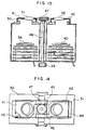
- two television cameras 30, 31 are combined by a connecting member 32 into a single body and used as a stereoscopic camera.
- Mount members 33, 34 of television cameras 30, 31 have formed at their openings threads 37, 38 for mounting lens tubes 35, 36.
- images are formed on the image-forming elements 39, 40 in the television camera. It ought to be noted that the positions of the centers of the mounting threads are not on the axes of the image-forming elements 39, 40, but located shifted towards the connecting member 32.
- Figs. 13 and 14 show another embodiment of this invention.
- lens mounts 41, 42 are so constructed as to be slidable. More specifically, the lens mounts 41, 42 are each made by bending a thin plate, and the ends of the plate are bent towards the inside. The bent portions are fitted into grooves provided in the end plates 43, 44 of the television cameras and are slidable.
- Rack gears 45, 46 are provided at part of the lens mounts 41, 42 and engage with a pinion 47.
- the pinion 47 is connected by a knob 49 with the intermediary of a shaft 48.
- a shading material 50 is attached to the inside of the lens mounts 41, 42 to cut off external light.
- the left and right lens mounts 41, 42 are caused to slide the same distance by the work of the pinion 47 and the racks 46, 47, so that the distance between the lenses can be changed easily. Therefore, if the distance between the observer and image-reproducing means changes, the adequate conditions can be obtained to produce a correct stereoscopic image by only correcting the distance between the lenses.
- the stereoscopic camera of this embodiment can be used for video recording at theaters or remote control of a manipulator, etc.
- the stereoscopic camera if made in a small size, will be effective in surgery using a TV.
- a natural stereoscopic vision without distortion can be obtained, so that the fatigue of the observer can be mitigated and he can continue observation for a long time. Furthermore, according to this invention, even when the position of the observer in relation to the image-reproducing means changes, the 0 lens position can be adjusted so that the observer can get the impression of depth or three dimensions from a synthesized image, and the fatigue of the observer can be lessened.
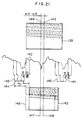
- Fig. 21 shows a first method of shifting the image center on the image-forming plane.
- the image-forming plane is scanned on every other scanning line, and a video signal 140 is thereby obtained.
- a horizontal or vertical synchronizing signal 141 is put in place of the portion of the video signal corresponding to that interval.
- the monitor screen 142 the screen is scanned from the point after the elapse of a fixed time t from when the synchronizing signal is given, thereby changing the video signal into variations of light.
- the center 143 of the image-forming plane substantially agrees with the center 144 of the monitor screen.
- a synchronizing signal 145 made to occur a little earlier than normal is combined with the video signal 140, it follows that the portion of the video signal advanced earlier than normal is scanned, and therefore, an image of a frame 146 is shown on the monitor screen 142. Therefore, on the monitor screen 146, the image shifts to the right. As a result, the image center 147 of the frame 146 comes to correspond to the center 148 of 0 the image shifted to left on the image-forming plane 139. If the synchronizing signal is delayed, the image shifts to left, so that the image center on the image-forming plane 139 shifts to right. By the foregoing operation, the timing of the synchronizing signal is either advanced or delayed relative to the normal state, and therefore, it is possible to adjust the position of the image center on the image-forming plane.
- Fig. 24 shows a synthesized signal 148a for a stereoscopic vision, in which signals from the left and right cameras are combined alternately.
- the ranges indicated by L are the video signal from the left camera and the ranges indicated by R are the video signal from the right camera.
- the horizontal synchronizing signals for the left and right cameras are shifted in the opposite directions across the wide vertical synchronizing signals, and a horizontal scanning signal 149 causes horizontal scanning to start after a fixed time t 1 following the horizontal synchronizing signal.
- the first horizontal scanning starts after passage of time t 2 following the vertical synchronizing signal.
- the relation of time t 1 and time t 2 is set so that the period of 5 the sawtooth waves is constant.
- a color burst signal of the horizontal synchronizing signal is omitted.
- Fig. 25 shows an embodiment by which the synchronizing signal of the stereoscopic camera is shifted.
- a synchronizing signal generates three kinds of pulse signals, the phase shifts of which are shown in (A), (B), and (C) of Fig. 26.
- Synchronized with synchronizing signals C L and C R provided by the synchronizing signal generator 150, a left camera 151 and a right camera 152 generate video signals 153, 154 and send the signals 25 to synchronizing signal synthesizers 155, 156.
- the synchronizing signal synthesizers 155, 156 combine the video signals 153, 154 with synchronizing signals S L , S R provided by the synchronizing signal generator 150, and output synthesized video signals 157, 158.
- a stereoscopic synthesizer 159 generates a synthesized stereoscopic video signal 160 formed by arranging synthesized video signals 157, 158 alternately, and outputs the synthesized signal.
- the synchronizing signal generator 150 outputs a pulse signal (B) (Fig. 26) on the lines of synchronizing signals C R , C L for the television cameras. To shift the image center to left, it is only necessary to send a pulse signal (A) leading the pulse signal (B) as the synchronizing signal S L or S R , and similarly, to shift the image center to right, it is only necessary to send a pulse signal (C) lagging the pulse signal (B) as the synchronizing signal S L or S R .
- phase shifts t p and t d the position of the image center can be selected arbitrarily.
- a second method of shifting the image center is to change the time t from when a horizontal synchronizing signal is issued until scanning is started.
- the synchronizing signals are incorporated therein at normal timing, but as for time t from when a horizontal synchronizing signal is given until scanning is started by a horizontal scanning signal, there is difference between t L and t R .
- switchover is done between time t L and t R in synchronism with the video signals of the left and right television cameras. Therefore, the same result can be achieved by the horizontal scanning signal as with the horizontal scanning signal 149.
- Fig. 28 shows an embodiment using the above-mentioned second method.
- the synchronizing signal generator 150 sends synchronizing signals C R , C L to the television cameras 151, 152. Though this is not illustrated, the video signals of the television cameras 151, 152 are combined with the synchronizing signals by an ordinary method, and the synthesized signals are sent as a synthesized stereoscopic video signal to the monitor.
- the synchronizing signal generator 150 sends a horizontal synchronizing signal S h to a horizontal scanning signal generator 163 of the monitor. This generator generates sawtooth waves 164, which are amplified by a horizontal scanning signal output unit 165 and used to drive a horizontal deflection coil 166.
- the synchronizing signal generator 150 generates pulse signals whose phases are shifted as indicated by (A), (B) and (C) of Fig. 29, outputs the pulse signals (B) on the lines of synchronizing signals C R , C L alternately, and outputs a pulse signal (B) or (C) alternately on the line of output S h to the horizontal scanning signal generator 163 in 0 synchronism with the synchronizing signals C R and C L . Therefore, the video signals of the left and right television cameras correspond to the horizontal synchronizing signal (A) or (C), and the positions of the image centers of the left and right television cameras can be changed individually by the phase shifts t p and t d .
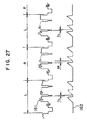
- Fig. 30 shows a still another embodiment of this invention.
- Fig. 31 shows waveforms at various parts.
- the method illustrated here is to adjust the timing of the horizontal scanning signal based on a synthesized stereoscopic video signal 167 sent from the television cameras.
- a synchronizing signal separator 168 separates the horizontal synchronizing signal 169 and the vertical synchronizing signal 170 from the synthesized stereoscopic video signal 167.
- the horizontal and vertical synchronizing signals 169, 170 are input into signal delay units 171, 172, where the signals are added with delay time to become horizontal synchronizing signals 173, 174.
- the horizontal synchronizing signals 173, 174 are input into the horizontal scanning signal generator 163, which generates sawtooth waves 164, which in turn are amplified by the horizontal scanning signal output unit 165 and used to drive the horizontal deflection coil 166.
- Delay times t 4 and t 6 from the horizontal synchronizing signal are switched over from one to another each time a vertical synchronizing signal 170 is input into the signal delay unit 171, and therefore, the left and right video signals correspond to the delays of the horizontal synchronizing signals.
- the delay times t 3 and t 5 from the vertical synchronizing signal have only to be set so that their pulse spacings are constant.
- a third method for shifting the image center is to use an image memory.
- Video signals obtained by two television cameras are converted to digital signals through A/D conversion.
- the digital video signals are input into image input circuits 275, 276, the video signals are recorded in image memories 277, 278.
- a stereoscopic image synthesizing and reading circuit 279 reads video signals from the two image memories 277, 278 alternately and synthesizes a video signal for stereoscopic viewing.
- the start address for reading the image memories the position of the image is shifted. For example, to advance video signals, the leading portion of the image memory is skipped and reading is started in the middle of the memory.
- reading is started at a portion just before the end of the image memory, and when the end point is reached, the reading process returns to the start address, or a dummy signal is added at the leading portion of the memory. In this way, video signals can be delayed.
- the enlargement ratio of a reproduced stereoscopic image is determined by the ratio between the space E between the eyes of the observer and the space e of the two television cameras. Since the binocular space E is constant for a particular observer, it is only necessary to change the space e between the two television cameras. In this step, it is necessary to abide by the two conditions mentioned earlier.
- the condition shown by Eq. (142) is not directly related to changing the space e , and is kept as it is.
- the condition shown by Eq. (145) indicates that if E and D are fixed, the ratio between a and e must be fixed.
- Fig. 33 shows an embodiment of means for adjusting the space e of the cameras.
- Two television cameras 280, 281 are fixed on slide bases 283, 284 supported by a slide rail 282.
- the slide bases are made to slide in the opposite directions by a screw rod 285 having threads in the opposite lead directions (LH and RH) formed at both ends thereof and by female screws 286, 287 engaging with the threads of the screw rod.
- the screw rod 285 is driven by a motor 288.
- the position of the observer relative to the monitor screen is closely related to the space, the sizes of the images and image-forming planes, and the lens focal length of the television cameras.
- it is necessary to observe an object at a specified position.
- being confined to a fixed position is often not desirable because freedom of action is lost.
- Eq. (174) is always equal to X. If, as shown above, the condition shown by Eq. (174) as well as the conditions shown by Eqs. (142), (143) are satisfied, the position of the image does not change even if the observer moves transversely.
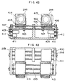
- Figs. 42 and 43 show an embodiment of the stereoscopic camera 297.
- Two television cameras 298, 299 are mounted on side bases 402, 403 supported by slide levers 400, 401.
- the female screws 404, 405 attached to the slide bases 402, 403 engage with screw rods 406, 407.
- the positions of the slide bases 402, 403 can be changed independently. Since sensors 410, 411 for position detection are interlocked with the screw rods 406, 407 with the intermediary of gears 412, 413, the slide bases 402, 403 can be positioned at specified positions by means of a position servo or the like.
- space adjusting means similar to the one shown in Fig. 33.
- This space adjusting means is used only to adjust the space between the lenses.
- the lenses used here are electric telephoto lenses 414, 415.
- the space between the lenses 414, 415 can be adjusted by the screw rod 285 having LH and RH threads formed on the opposite sides thereof.
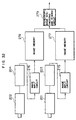
- Fig. 44 shows a control block diagram.
- a magnetic sensor control unit 416 inputs signals representing the distance D from the observer to the screen and the transverse moving distance L relative to the center line of the monitor screen into an arithmetic and control unit 417.
- the observer's binocular space E and the enlargement ratio of the stereoscopic image are input into the arithmetic and control unit 417.
- the arithmetric and control unit 417 obtains e from signals of E and ⁇ at an arithmetic block 419, and outputs e to a controller 420 of the television camera space adjusting unit to set the value of e.
- An arithmetic block 421 obtains a from signals of D, and outputs a to a control unit 422 for the robot.
- An arithmetic block 423 obtains l from L and ⁇ , and outputs l to the control unit 422 for the robot. As a result, the robot 300 moves so that the position of the stereoscopic camera 297 becomes predetermined by values of a and l.
- An arithmetic block 424 obtains the distance d between the optical centers of the lenses and the image-forming planes from the image-forming plane size a and the monitor screen size S, which have been predetermined, and sends the distance d to the controllers 425, 426 for zoom lenses in order to adjust the optical system.
- An arithmetic block 427 obtains the moving distance l s of the image-forming planes from data on a , d , and l.
- arithmetic blocks 428, 429 obtain the positions X R and X L , which data are then input into position controllers 430, 431, which control the television cameras to move to a specified position.
- the space of the lenses of the television cameras can be adjusted, the enlargement ratio ⁇ of the stereoscopic image, and the stereoscopic image is prevented from being distorted or moved when the observer changes his position.
- video signals of two television cameras can be shifted in parallel, so that an accurate stereoscopic vision without distortion can be obtained.
- the observer is away from the specified position, he can get a correct stereoscopic image.
Claims (10)
- Stereoskopisches Bildsystem, das die Untersuchung eines stereoskopischen Bilds aufgrund von Parallaxe ermöglicht, durch ein Reproduzieren auf einem einzelnen Schirm (19) in Bildreproduzierungsmitteln von zwei Arten von Bildern eines Objekts, welche von zwei Bildeinheiten erfaßt werden und zwischen denen die Parallaxe auftritt und durch ein Untersuchen der Bilder derart, daß das linke und das rechte Auge des Untersuchers nur die getrennten Bilder untersucht, die von den separaten Bildeinheiten erzeugt werden, entsprechend dem linken und rechten Auge, wobei die Normalen der entsprechenden Bilderzeugungsebenen (17, 18) der beiden Bildeinheiten parallel angeordnet sind, wobei der Abstand e zwischen den optischen Mitten (28, 29) der Linsen (51, 52) der beiden Bildeinheiten derart eingestellt ist, daß er kleiner ist als der Abstand b zwischen den Mitten der Bilderzeugungsebenen, und wobei ein Verhältnis E/(b-e) zwischen dem Abstand E des binokularen Raums des Beobachters und des Abstands b-e, erhalten durch ein Subtrahieren des Abstands e zwischen den Linsen von dem Abstand b zwischen den Mitten der Bilderzeugungsebenen der beiden Bildeinheiten und ein Verhältnis D/d zwischen dem Abstand D von dem Beobachter zu dem Schirm (19) und dem Abstand d der Bilderzeugungsebenen zu den optischen Mitten (28, 29) der Linsen (51, 52) im wesentlichen gleich zu dem Verhältnis f der Größe des Bilds auf dem Schirm (19) zu der Größe der Bilder auf den Bilderzeugungsebenen (17, 18) sind, wobei sich die folgende Gleichung ergibt: D/d = E/(b-e) = f.
- Stereoskopisches Bildsystem nach Anspruch 1,
dadurch gekennzeichnet, daß
Änderungsmittel des Mittenabstands zum Ändern des Abstands (e) zwischen den optischen Mitten (28, 29) der Linsen (51, 52) der beiden Bildeinheiten vorgesehen sind, wobei durch die Änderungsmittel des Mittenabstands der Abstand (e) zwischen den optischen Mitten (28, 29) der Linsen (51, 52) kürzer gemacht wird als der Abstand (b) zwischen den Mitten der Bilderzeugungsebenen (17, 18). - Stereoskopisches Bildsystem nach Anspruch 1 oder 2,
dadurch gekennzeichnet, daß
die Änderungsmittel des Mittenabstands einen Mechanismus aufweisen, durch den sich die optischen Achsen der Linsen (51, 52) um den gleichen Abstand in Richtungen senkrecht zueinander und gegenläufig zueinander bewegen können. - Stereoskopisches Bildsystem nach irgendeinem der Ansprüche 1-3,
dadurch gekennzeichnet, daß
der Verschiebemechanismus Zahnstangen (45, 46) enthält, die mit den entsprechenden Linsen (51, 52) verbunden sind und ein Ritzel (47) enthält, das mit den Zahnstangen in Eingriff steht. - Stereoskopisches Bildsystem, das die Untersuchung eines stereoskopischen Bildes aufgrund einer Parallaxe ermöglicht, durch ein Reproduzieren auf einem einzelnen Schirm (19) in Bildreproduzierungsmitteln von zwei Arten von Bildern eines Objekts, die von zwei Bildeinheiten (151, 152) erzeugt werden und zwischen denen eine Parallaxe auftritt und durch ein Beobachten der Bilder derart, daß das linke und das rechte Auge des Beobachters nur die separaten Bilder beobachten, die durch die separaten Bildeinheiten entsprechend dem linken und rechten Auge erzeugt werden, wobei die Normalen der entsprechenden Bilderzeugungsebenen (17, 18) der beiden Bildeinheiten (151, 152) parallel angeordnet sind und wobei elektronische Schaltungsmittel (150) vorgesehen sind, zum Verschieben nach links oder rechts der Position eines reproduzierten Bilds auf einem Bildschirm, basierend auf Bildsignalen, die von den Bildeinheiten (151, 152) ausgelesen werden, durch Verschieben einer Anzeigezeitabfolge beim Anzeigen des Bildsignals auf dem Bildschirm derart, daß, wenn der Abstand (e) zwischen den optischen Mitten der Linsen der beiden Bildeinheiten kürzer ist als der Abstand (b) zwischen den Mitten der entsprechenden Bilderzeugungsebenen und wenn der Abstand (e) zwischen den optischen Mitten der Linsen der beiden Bilderzeugungseinheiten (151, 152) derart eingestellt wird, daß er kleiner ist als der Abstand (b) zwischen den Mitten der Bilderzeugungseinheiten, das Verhältnis E/(b-e) zwischen dem Abstand (E) des binokularen Raums des Untersuchers und dem Abstand (b-e) erhalten durch ein Subtrahieren des Abstands (e) zwischen den Linsen von dem Abstand (b) zwischen den Mitten der Bilderzeugungseinheiten der beiden Bildeinheiten (151, 152) und ein Verhältnis D/d zwischen dem Abstand (D) des Untersuchers zu dem Schirm (19) und dem Abstand (d) von den Bilderzeugungsebenen zu den optischen Mitten (28, 29) der Linsen (51, 52) im wesentlichen gleich zu einem Verhältnis f der Größe eines Bilds auf dem Schirm (19) zu der Größe der Bilder auf den Bilderzeugungsebenen (17, 18) sind, wobei dies die folgende Gleichung ergibt: D/d = E/(b-e) = f.
- Stereoskopisches Bildsystem nach Anspruch 5,
dadurch gekennzeichnet, daß
die elektronischen Schaltungsmittel einen Synchronisationssignalgenerator (150) zum Erzeugen von Synchronisationssignalen (CR und CL) enthalten, die den Bildeinheiten (151, 152) zugeführt werden, und zum Erzeugen eines horizontalen Synchronisationssignals (Sh), das einem Horizontalabtastsignalgenerator (163) eines Monitors zugeführt wird, der den Bildschirm enthält, wobei der Synchronisationssignalgenerator (150) die Zeitabfolge des Horizontalsynchronisationssignals (Sh) vorverstellen oder verzögern kann, wenn das Horizontalsynchronisationssignal (Sh) mit den von den Bildeinheiten (151, 152) erhaltenen Bildsignalen synthetisiert wird, wobei die synthetisierten Signale anschließend dem Bildschirm zur Anzeige zugeführt werden. - Stereoskopisches Bildsystem nach Anspruch 5,
dadurch gekennzeichnet, daß
die elektronischen Schaltungsmittel eine Zeiteinstellschaltung sind, die auf der Seite der Bildreproduktionsmittel vorgesehen ist und einen Synchronisationssignalseparator (168) enthält, zum Trennen eines horizontalen Synchronisationssignals (169) und eines vertikalen Synchronisationssignals (170) von einem synthetisierten stereoskopischen Videosignal (167), weiterhin Signalzverzögerungseinheiten (171, 172) enthält, zum Vorsehen einer Zeitverschiebung des horizontalen Synchronisationssignals (169) und des vertikalen Synchronisationssignals (170) und einen horizontalen Abtastsignalgenerator (163) enthält, dem die verzögerten Synchronisationssignale zugeführt werden und der horizontale Abtastsignale (164) erzeugt, die einem Monitor zugeführt werden, der den Bildschirm enthält, wodurch die Position des Bilds auf dem Bildschirm basierend auf der von den Signalverzögerungseinheiten (171, 172) erzeugten Zeitverschiebung verschoben werden kann. - Stereoskopisches Bildsystem nach irgendeinem der Ansprüche 5 bis 7,
dadurch gekennzeichnet, daß
die elektronischen Schaltungsmittel zwei Bildspeicher (277, 278) zum Speichern von Videosignalen der beiden Bildeinheiten (17, 18) enthalten und eine stereoskopische Bildsynthetisierungsschaltung (279) zum Lesen von Videosignalen und zum Ändern einer Startadresse, wenn die in dem Bildspeicher gespeicherten Videosignale alternierend ausgelesen werden. - Stereoskopisches Bildsystem mit linken und rechten Fernsehbildeinheiten (280, 281 in Fig. 33), die derart montiert sind, daß ihre Bilderzeugungsebenen (17, 18) koplanar sind und die optischen Achsen der koplanaren Linsen der beiden Fernsehbildeinheiten parallel und normal zu den Bilderzeugungsebenen angeordnet sind, und mit Raumeinstellmitteln (282-288) zum Einstellen eines Abstands (e) zwischen den beiden Bildeinheiten und dadurch zwischen den optischen Achsen der Linsen, während die optischen Achsen parallel gehalten werden,
dadurch gekennzeichnet, daß
zum Vergrößern oder Reduzieren der Größe eines stereoskopischen Monitorbilds, erzeugt durch die beiden Bildeinheiten (280, 281) auf einem Fernsehmonitorschirm, Steuermittel (417) vorgesehen sind, zum Berechnen des Abstands (e) aus einem Vergrößerungsverhältnis (ν) des stereoskopischen Bilds und eines Abstands (E) des binokularen Raums eines Untersuchers des stereoskopischen Bilds gemäß der Gleichung
- Stereoskopisches Bildsystem mit linken und rechten Fernsehbildeinheiten (298, 299 in Fig. 42 und 43), die derart montiert sind, daß ihre Bilderzeugungsebenen (17, 18) koplanar sind und die optischen Achsen der koplanaren Linsen (414, 415) der beiden Fernsehbildeinheiten parallel und normal zu den Bilderzeugungsebenen angeordnet sind,
gekennzeichnet durchErfassungsmittel (293) zum Erfassen der Position der Augen eines Beobachters bezüglich einem Monitorbild, das durch die beiden Bildeinheiten (298, 299) auf einem Fernsehmonitorbild erzeugt wird,Bilderzeugungsebenenbewegungsmittel (282-288) zum Bewegen der beiden Fernsehbildeinheiten (298, 299) zusammen mit ihren Bilderzeugungsebenen in eine Richtung zum Annähern oder zum Entfernen zueinander bzw. voneinander, während diese in der koplanaren Anordnung gehalten werden,Zoomlinsen (414, 415) mit vorbestimmten Zoomraten, die jeweils für die Fernsehbildeinheiten vorgesehen sind,separate Zoomlinsenbewegungsmittel (400-413) zum Bewegen der Zoomlinsen (414, 415) in eine Richtung zum Annähern oder zum Entfernen zueinander bzw. voneinander, während diese in der koplanaren Anordnung gehalten werden,Bewegungsmittel (300) zum Bewegen einer Basis, auf der die beiden Bildeinheiten (298, 299) und die beiden Zoomlinsen (414, 415) montiert sind, nach vorne und hinten und in laterale Richtungen, undSteuermittel (417) zum Steuern des Abstands (e) zwischen den beiden Bildeinheiten (298, 299), der Zoomrate (Brennweite d), der Positionen (XR, XL) der beiden Bildeinheiten und der Position einer stereoskopischen Kamera (297), in der die beiden Bildeinheiten (298, 299) und die beiden Zoomlinsen (414, 415) enthalten sind, derart, daß sich gerade Linien, die ein zu untersuchendes Objekt (129) und die Mitte jeder der Zoomlinsen (414, 415) verbinden, mit der Mitte der Bilderzeugungsebenen (118, 119) der beiden Bildeinheiten (298, 299) decken.
Applications Claiming Priority (4)
| Application Number | Priority Date | Filing Date | Title |
|---|---|---|---|
| JP278023/89 | 1989-10-25 | ||
| JP1278023A JP2581601B2 (ja) | 1989-10-25 | 1989-10-25 | 立体カメラ及び立体映像システム |
| JP225316/90 | 1990-08-29 | ||
| JP2225316A JPH04108288A (ja) | 1990-08-29 | 1990-08-29 | 立体映像装置 |
Publications (3)
| Publication Number | Publication Date |
|---|---|
| EP0425985A2 EP0425985A2 (de) | 1991-05-08 |
| EP0425985A3 EP0425985A3 (en) | 1992-04-15 |
| EP0425985B1 true EP0425985B1 (de) | 1997-06-11 |
Family
ID=26526563
Family Applications (1)
| Application Number | Title | Priority Date | Filing Date |
|---|---|---|---|
| EP90120317A Expired - Lifetime EP0425985B1 (de) | 1989-10-25 | 1990-10-23 | Stereoskopisches bilderzeugendes System |
Country Status (3)
| Country | Link |
|---|---|
| US (1) | US5119189A (de) |
| EP (1) | EP0425985B1 (de) |
| DE (1) | DE69030911T2 (de) |
Cited By (1)
| Publication number | Priority date | Publication date | Assignee | Title |
|---|---|---|---|---|
| TWI805174B (zh) * | 2022-01-07 | 2023-06-11 | 五鈴光學股份有限公司 | 多模態高光譜相機 |
Families Citing this family (64)
| Publication number | Priority date | Publication date | Assignee | Title |
|---|---|---|---|---|
| FR2670349A1 (fr) * | 1990-12-10 | 1992-06-12 | France Etat | Dispositif de correction geometrique des images video en relief. |
| WO1993022699A1 (en) * | 1992-04-24 | 1993-11-11 | Depth Enhancement Inc | Three-dimensional visualization by altered multiple two-dimensional perspective imagery |
| US5321353A (en) * | 1992-05-13 | 1994-06-14 | Storage Technolgy Corporation | System and method for precisely positioning a robotic tool |
| JP3257640B2 (ja) * | 1992-06-09 | 2002-02-18 | オリンパス光学工業株式会社 | 立体視内視鏡装置 |
| JPH0795623A (ja) * | 1993-06-25 | 1995-04-07 | Sanyo Electric Co Ltd | 立体撮像装置 |
| DE69417824D1 (de) * | 1993-08-26 | 1999-05-20 | Matsushita Electric Ind Co Ltd | Stereoskopischer Abtastapparat |
| US5976076A (en) * | 1995-02-22 | 1999-11-02 | Kolff; Jack | Stereo laparoscope with synchronized optics |
| US5917940A (en) * | 1996-01-23 | 1999-06-29 | Nec Corporation | Three dimensional reference image segmenting method and device and object discrimination system |
| DE69706611T2 (de) * | 1996-06-27 | 2002-07-04 | Toshiba Kawasaki Kk | Stereoskopisches Display-System und -Verfahren |
| DE19836681B4 (de) * | 1997-09-19 | 2008-03-27 | Carl Zeiss Ag | Stereoskopisches Aufnahme- und Wiedergabesystem |
| US6478730B1 (en) | 1998-09-09 | 2002-11-12 | Visionscope, Inc. | Zoom laparoscope |
| GB9827546D0 (en) * | 1998-12-15 | 1999-02-10 | Street Graham S B | Apparatus and method for image control |
| DE19905452C2 (de) * | 1999-02-09 | 2001-02-22 | Deutsch Zentr Luft & Raumfahrt | Digitale Stereokamera |
| US6668327B1 (en) | 1999-06-14 | 2003-12-23 | Sun Microsystems, Inc. | Distributed authentication mechanisms for handling diverse authentication systems in an enterprise computer system |
| US6767321B2 (en) | 1999-10-04 | 2004-07-27 | Robert Czarnek | Stereo laparoscope with discrete working distance |
| US6687399B1 (en) * | 2000-08-03 | 2004-02-03 | Silicon Integrated Systems Corp. | Stereo synchronizing signal generator for liquid crystal shutter glasses |
| KR100360825B1 (ko) * | 2000-09-01 | 2002-11-13 | 한국해양연구원 | 거리측정이 가능한 단동형 수중 스테레오 카메라 |
| FI117146B (fi) * | 2001-06-18 | 2006-06-30 | Karri Tapani Palovuori | Suljintoimintoon perustuva laitteisto stereo- tai monikanavakuvan projisoimiseksi |
| US7904826B2 (en) * | 2002-03-29 | 2011-03-08 | Microsoft Corporation | Peek around user interface |
| US20060119707A1 (en) * | 2002-09-12 | 2006-06-08 | Merrell John D | Personal video message system |
| US20040056948A1 (en) * | 2002-09-23 | 2004-03-25 | Gibson Robert John | Multi-play theatre |
| AU2002355052A1 (en) * | 2002-11-28 | 2004-06-18 | Seijiro Tomita | Three-dimensional image signal producing circuit and three-dimensional image display apparatus |
| DE102005063503B4 (de) * | 2005-03-10 | 2011-05-19 | Inaba, Minoru, Oyama | 3D-Display und 3D-Projektor |
| JP4291862B2 (ja) | 2007-07-04 | 2009-07-08 | 稔 稲葉 | 立体テレビジョンシステム及び立体テレビジョン受像機 |
| USD624952S1 (en) | 2008-10-20 | 2010-10-05 | X6D Ltd. | 3D glasses |
| USD603445S1 (en) | 2009-03-13 | 2009-11-03 | X6D Limited | 3D glasses |
| USD666663S1 (en) | 2008-10-20 | 2012-09-04 | X6D Limited | 3D glasses |
| USRE45394E1 (en) | 2008-10-20 | 2015-03-03 | X6D Limited | 3D glasses |
| US20110234775A1 (en) * | 2008-10-20 | 2011-09-29 | Macnaughton Boyd | DLP Link System With Multiple Projectors and Integrated Server |
| US20110205347A1 (en) * | 2008-11-17 | 2011-08-25 | X6D Limited | Universal 3d glasses for use with televisions |
| US20110216176A1 (en) * | 2008-11-17 | 2011-09-08 | Macnaughton Boyd | 3D Glasses With RF Synchronization |
| US8542326B2 (en) * | 2008-11-17 | 2013-09-24 | X6D Limited | 3D shutter glasses for use with LCD displays |
| CA2684513A1 (en) | 2008-11-17 | 2010-05-17 | X6D Limited | Improved performance 3d glasses |
| JP4863527B2 (ja) * | 2009-12-01 | 2012-01-25 | 稔 稲葉 | 立体映像撮像装置 |
| EP2406962B1 (de) | 2009-03-09 | 2015-10-07 | Zayo France | Zum erfassen mehrerer bilder für multiskopische restitution mit gesteuerter deformation ausgelegtes system und verfahren |
| FR2942886B1 (fr) * | 2009-03-09 | 2011-05-06 | Telerelief | Dispositif de captation simultanee d'une pluralite de prises de vues pour une restitution en relief a deformation controlee sur un dispositif multiscopique |
| USD646451S1 (en) | 2009-03-30 | 2011-10-04 | X6D Limited | Cart for 3D glasses |
| JP5409107B2 (ja) * | 2009-05-13 | 2014-02-05 | 任天堂株式会社 | 表示制御プログラム、情報処理装置、表示制御方法、および情報処理システム |
| USD672804S1 (en) | 2009-05-13 | 2012-12-18 | X6D Limited | 3D glasses |
| USD650956S1 (en) | 2009-05-13 | 2011-12-20 | X6D Limited | Cart for 3D glasses |
| KR20120039563A (ko) * | 2009-07-02 | 2012-04-25 | 톰슨 라이센싱 | 3차원(3d) 투영에 대한 차동 왜곡 보정을 위한 방법 및 시스템 |
| IN2012DN00515A (de) * | 2009-07-29 | 2015-08-21 | Thomson Licensing | |
| US20110025821A1 (en) * | 2009-07-30 | 2011-02-03 | Dell Products L.P. | Multicast stereoscopic video synchronization |
| US20110063418A1 (en) * | 2009-08-04 | 2011-03-17 | Parker Matthew A | Integrated Mount and Control Device for Stereoscopic Video |
| WO2011019398A1 (en) * | 2009-08-12 | 2011-02-17 | Thomson Licensing | Method and system for crosstalk and distortion corrections for three-dimensional (3d) projection |
| JP5405264B2 (ja) | 2009-10-20 | 2014-02-05 | 任天堂株式会社 | 表示制御プログラム、ライブラリプログラム、情報処理システム、および、表示制御方法 |
| JP4754031B2 (ja) * | 2009-11-04 | 2011-08-24 | 任天堂株式会社 | 表示制御プログラム、情報処理システム、および立体表示の制御に利用されるプログラム |
| USD671590S1 (en) | 2010-09-10 | 2012-11-27 | X6D Limited | 3D glasses |
| USD692941S1 (en) | 2009-11-16 | 2013-11-05 | X6D Limited | 3D glasses |
| USD669522S1 (en) | 2010-08-27 | 2012-10-23 | X6D Limited | 3D glasses |
| JP2011139296A (ja) * | 2009-12-28 | 2011-07-14 | Sony Corp | 映像信号処理装置及び映像信号処理方法 |
| EP2355526A3 (de) | 2010-01-14 | 2012-10-31 | Nintendo Co., Ltd. | Computerlesbares Speichermedium mit einem Anzeigesteuerungsprogramm darauf, Anzeigesteuerungsvorrichtung, Anzeigesteuerungssystem und Anzeigesteuerungsverfahren |
| USD662965S1 (en) | 2010-02-04 | 2012-07-03 | X6D Limited | 3D glasses |
| JP5540848B2 (ja) * | 2010-04-08 | 2014-07-02 | ソニー株式会社 | 映像信号処理装置、表示装置、表示方法及びプログラム |
| US9693039B2 (en) | 2010-05-27 | 2017-06-27 | Nintendo Co., Ltd. | Hand-held electronic device |
| USD664183S1 (en) | 2010-08-27 | 2012-07-24 | X6D Limited | 3D glasses |
| JP5709545B2 (ja) * | 2011-01-18 | 2015-04-30 | キヤノン株式会社 | 撮像装置 |
| JP2012249137A (ja) * | 2011-05-30 | 2012-12-13 | Sony Corp | 記録装置、記録方法、再生装置、再生方法、プログラム、および記録再生装置 |
| USD711959S1 (en) | 2012-08-10 | 2014-08-26 | X6D Limited | Glasses for amblyopia treatment |
| JP6233870B2 (ja) | 2012-08-28 | 2017-11-22 | 稔 稲葉 | 立体映像受像機 |
| TWI503618B (zh) * | 2012-12-27 | 2015-10-11 | Ind Tech Res Inst | 深度影像擷取裝置、其校正方法與量測方法 |
| CN103744256B (zh) * | 2013-10-21 | 2017-03-08 | 浙江理工大学 | 实现360度可调摄像机的旋转装置 |
| CA2993561C (en) * | 2018-01-31 | 2020-06-30 | Synaptive Medical (Barbados) Inc. | System for three-dimensional visualization |
| CN113775885A (zh) * | 2021-09-27 | 2021-12-10 | 安徽捷呈科技文化有限公司 | 一种利于视频制作的多方位图像同步采集装置 |
Family Cites Families (9)
| Publication number | Priority date | Publication date | Assignee | Title |
|---|---|---|---|---|
| US3980394A (en) * | 1973-10-16 | 1976-09-14 | Zapf Kenyon L | Stereo viewing |
| NL8005650A (nl) * | 1980-10-14 | 1982-05-03 | Philips Nv | Drie-dimensionaal televisie-beeldweergeefsysteem en daarvoor geschikte beeldopneeminrichting en beeldweergeefinrichting. |
| JPS5831691A (ja) * | 1981-08-19 | 1983-02-24 | Matsushita Electric Ind Co Ltd | 立体テレビジヨン装置 |
| GB2147762A (en) * | 1983-10-10 | 1985-05-15 | Audim Sa | An artifical binocular vision system |
| US4677468A (en) * | 1984-08-13 | 1987-06-30 | Nec Home Electronics Ltd. | Stereoscopic television image-pickup device display device |
| GB8430980D0 (en) * | 1984-12-07 | 1985-01-16 | Robinson M | Generation of apparently three-dimensional images |
| NL8500141A (nl) * | 1985-01-21 | 1986-08-18 | Delft Tech Hogeschool | Werkwijze voor het bij een waarnemer opwekken van een drie-dimensionale indruk vanuit een twee-dimensionale afbeelding. |
| JPH01246989A (ja) * | 1988-03-29 | 1989-10-02 | Kanji Murakami | 立体撮像ビデオカメラ |
| US4956705A (en) * | 1989-03-10 | 1990-09-11 | Dimensional Visions Group | Electronic method and apparatus for stereoscopic photography |
-
1990
- 1990-10-23 EP EP90120317A patent/EP0425985B1/de not_active Expired - Lifetime
- 1990-10-23 DE DE69030911T patent/DE69030911T2/de not_active Expired - Fee Related
- 1990-10-24 US US07/602,864 patent/US5119189A/en not_active Expired - Fee Related
Cited By (1)
| Publication number | Priority date | Publication date | Assignee | Title |
|---|---|---|---|---|
| TWI805174B (zh) * | 2022-01-07 | 2023-06-11 | 五鈴光學股份有限公司 | 多模態高光譜相機 |
Also Published As
| Publication number | Publication date |
|---|---|
| EP0425985A3 (en) | 1992-04-15 |
| DE69030911T2 (de) | 1997-11-06 |
| DE69030911D1 (de) | 1997-07-17 |
| US5119189A (en) | 1992-06-02 |
| EP0425985A2 (de) | 1991-05-08 |
Similar Documents
| Publication | Publication Date | Title |
|---|---|---|
| EP0425985B1 (de) | Stereoskopisches bilderzeugendes System | |
| US5835133A (en) | Optical system for single camera stereo video | |
| EP0744872B1 (de) | Stereoskopisches Bildanzeigeverfahren und -gerät | |
| US5625408A (en) | Three-dimensional image recording/reconstructing method and apparatus therefor | |
| US5510832A (en) | Synthesized stereoscopic imaging system and method | |
| US6414709B1 (en) | Methods and apparatus for zooming during capture and reproduction of 3-dimensional images | |
| EP1083454B1 (de) | Vorrichtung zur Darstellung stereoskopischer Bilder und Bildaufnahmevorrichtung dafür | |
| US5933664A (en) | Method of using a parallax scanning lens aperture in a range-finding application | |
| US5953054A (en) | Method and system for producing stereoscopic 3-dimensional images | |
| KR100375465B1 (ko) | 입체 영상 표시장치 | |
| US20060203085A1 (en) | There dimensional image signal producing circuit and three-dimensional image display apparatus | |
| US5949477A (en) | Three dimensional stereoscopic television system | |
| EP0644701A2 (de) | Bildaufnahme- und anzeigesystem | |
| Ezra et al. | New autostereoscopic display system | |
| EP0707287B1 (de) | Gerät und Verfahren zur Bildverarbeitung | |
| WO2002015595A1 (en) | A method and system of revision for 3-dimensional image | |
| US4994898A (en) | Color television system for processing signals from a television camera to produce a stereoscopic effect | |
| KR100399047B1 (ko) | 교차축 입체 카메라의 주시각 제어 장치 및 그 방법 | |
| Jones Jr et al. | VISIDEP (tm): visual image depth enhancement by parallax induction | |
| JP2581601B2 (ja) | 立体カメラ及び立体映像システム | |
| JP2005045338A (ja) | 車載用三次元表示用モニタシステム | |
| JPH04108288A (ja) | 立体映像装置 | |
| JPH06276552A (ja) | 立体画像撮影装置および画像提示装置 | |
| WO1995013564A1 (en) | Method and apparatus for visualizing two-dimensional motion picture images in three dimensions | |
| JP2002344997A (ja) | 立体映像信号の編集方法、及び立体映像撮影用のビデオカメラの光学アダプター装置 |
Legal Events
| Date | Code | Title | Description |
|---|---|---|---|
| PUAI | Public reference made under article 153(3) epc to a published international application that has entered the european phase |
Free format text: ORIGINAL CODE: 0009012 |
|
| 17P | Request for examination filed |
Effective date: 19901120 |
|
| AK | Designated contracting states |
Kind code of ref document: A2 Designated state(s): DE FR |
|
| PUAL | Search report despatched |
Free format text: ORIGINAL CODE: 0009013 |
|
| AK | Designated contracting states |
Kind code of ref document: A3 Designated state(s): DE FR |
|
| 17Q | First examination report despatched |
Effective date: 19940210 |
|
| GRAG | Despatch of communication of intention to grant |
Free format text: ORIGINAL CODE: EPIDOS AGRA |
|
| GRAH | Despatch of communication of intention to grant a patent |
Free format text: ORIGINAL CODE: EPIDOS IGRA |
|
| GRAH | Despatch of communication of intention to grant a patent |
Free format text: ORIGINAL CODE: EPIDOS IGRA |
|
| GRAA | (expected) grant |
Free format text: ORIGINAL CODE: 0009210 |
|
| AK | Designated contracting states |
Kind code of ref document: B1 Designated state(s): DE FR |
|
| REF | Corresponds to: |
Ref document number: 69030911 Country of ref document: DE Date of ref document: 19970717 |
|
| ET | Fr: translation filed | ||
| PLBE | No opposition filed within time limit |
Free format text: ORIGINAL CODE: 0009261 |
|
| STAA | Information on the status of an ep patent application or granted ep patent |
Free format text: STATUS: NO OPPOSITION FILED WITHIN TIME LIMIT |
|
| 26N | No opposition filed | ||
| PGFP | Annual fee paid to national office [announced via postgrant information from national office to epo] |
Ref country code: FR Payment date: 19990817 Year of fee payment: 10 |
|
| PGFP | Annual fee paid to national office [announced via postgrant information from national office to epo] |
Ref country code: DE Payment date: 19991230 Year of fee payment: 10 |
|
| PG25 | Lapsed in a contracting state [announced via postgrant information from national office to epo] |
Ref country code: FR Free format text: LAPSE BECAUSE OF NON-PAYMENT OF DUE FEES Effective date: 20010629 |
|
| PG25 | Lapsed in a contracting state [announced via postgrant information from national office to epo] |
Ref country code: DE Free format text: LAPSE BECAUSE OF NON-PAYMENT OF DUE FEES Effective date: 20010703 |
|
| REG | Reference to a national code |
Ref country code: FR Ref legal event code: ST |