EP0425981B1 - Bloc à canaux de chauffe - Google Patents
Bloc à canaux de chauffe Download PDFInfo
- Publication number
- EP0425981B1 EP0425981B1 EP90120304A EP90120304A EP0425981B1 EP 0425981 B1 EP0425981 B1 EP 0425981B1 EP 90120304 A EP90120304 A EP 90120304A EP 90120304 A EP90120304 A EP 90120304A EP 0425981 B1 EP0425981 B1 EP 0425981B1
- Authority
- EP
- European Patent Office
- Prior art keywords
- groove
- heating element
- tubular heating
- hot runner
- runner unit
- Prior art date
- Legal status (The legal status is an assumption and is not a legal conclusion. Google has not performed a legal analysis and makes no representation as to the accuracy of the status listed.)
- Expired - Lifetime
Links
- 238000010438 heat treatment Methods 0.000 claims abstract description 53
- 229920003023 plastic Polymers 0.000 claims abstract description 10
- 239000004033 plastic Substances 0.000 claims abstract description 10
- 239000000463 material Substances 0.000 claims abstract description 5
- RYGMFSIKBFXOCR-UHFFFAOYSA-N Copper Chemical compound [Cu] RYGMFSIKBFXOCR-UHFFFAOYSA-N 0.000 claims description 5
- 150000001875 compounds Chemical class 0.000 claims description 5
- 229910052802 copper Inorganic materials 0.000 claims description 5
- 239000010949 copper Substances 0.000 claims description 5
- 238000001746 injection moulding Methods 0.000 claims description 4
- 238000000034 method Methods 0.000 claims description 4
- 238000003825 pressing Methods 0.000 claims description 4
- 239000010935 stainless steel Substances 0.000 claims description 4
- 229910001220 stainless steel Inorganic materials 0.000 claims description 4
- 238000002347 injection Methods 0.000 abstract description 4
- 239000007924 injection Substances 0.000 abstract description 4
- 238000009434 installation Methods 0.000 abstract 1
- 238000007493 shaping process Methods 0.000 abstract 1
- 229920002994 synthetic fiber Polymers 0.000 abstract 1
- 239000004568 cement Substances 0.000 description 4
- 230000006835 compression Effects 0.000 description 4
- 238000007906 compression Methods 0.000 description 4
- CPLXHLVBOLITMK-UHFFFAOYSA-N magnesium oxide Inorganic materials [Mg]=O CPLXHLVBOLITMK-UHFFFAOYSA-N 0.000 description 4
- 239000000395 magnesium oxide Substances 0.000 description 4
- AXZKOIWUVFPNLO-UHFFFAOYSA-N magnesium;oxygen(2-) Chemical compound [O-2].[Mg+2] AXZKOIWUVFPNLO-UHFFFAOYSA-N 0.000 description 4
- 238000009413 insulation Methods 0.000 description 3
- 229910052751 metal Inorganic materials 0.000 description 3
- 239000002184 metal Substances 0.000 description 3
- 229910000831 Steel Inorganic materials 0.000 description 2
- 239000003795 chemical substances by application Substances 0.000 description 2
- 239000004020 conductor Substances 0.000 description 2
- 238000004382 potting Methods 0.000 description 2
- 239000000843 powder Substances 0.000 description 2
- 239000007921 spray Substances 0.000 description 2
- 239000010959 steel Substances 0.000 description 2
- 229910000881 Cu alloy Inorganic materials 0.000 description 1
- CWYNVVGOOAEACU-UHFFFAOYSA-N Fe2+ Chemical compound [Fe+2] CWYNVVGOOAEACU-UHFFFAOYSA-N 0.000 description 1
- 230000006978 adaptation Effects 0.000 description 1
- 229910052782 aluminium Inorganic materials 0.000 description 1
- XAGFODPZIPBFFR-UHFFFAOYSA-N aluminium Chemical compound [Al] XAGFODPZIPBFFR-UHFFFAOYSA-N 0.000 description 1
- 238000005266 casting Methods 0.000 description 1
- 238000010276 construction Methods 0.000 description 1
- 230000007547 defect Effects 0.000 description 1
- 238000009826 distribution Methods 0.000 description 1
- 229920006351 engineering plastic Polymers 0.000 description 1
- 230000001771 impaired effect Effects 0.000 description 1
- 238000007373 indentation Methods 0.000 description 1
- 230000005923 long-lasting effect Effects 0.000 description 1
- 238000004519 manufacturing process Methods 0.000 description 1
- 230000010355 oscillation Effects 0.000 description 1
- 238000007789 sealing Methods 0.000 description 1
- 239000000243 solution Substances 0.000 description 1
- 230000007704 transition Effects 0.000 description 1
Images

Classifications
-
- B—PERFORMING OPERATIONS; TRANSPORTING
- B29—WORKING OF PLASTICS; WORKING OF SUBSTANCES IN A PLASTIC STATE IN GENERAL
- B29C—SHAPING OR JOINING OF PLASTICS; SHAPING OF MATERIAL IN A PLASTIC STATE, NOT OTHERWISE PROVIDED FOR; AFTER-TREATMENT OF THE SHAPED PRODUCTS, e.g. REPAIRING
- B29C45/00—Injection moulding, i.e. forcing the required volume of moulding material through a nozzle into a closed mould; Apparatus therefor
- B29C45/17—Component parts, details or accessories; Auxiliary operations
- B29C45/26—Moulds
- B29C45/27—Sprue channels ; Runner channels or runner nozzles
- B29C45/2737—Heating or cooling means therefor
- B29C45/2738—Heating or cooling means therefor specially adapted for manifolds
-
- H—ELECTRICITY
- H05—ELECTRIC TECHNIQUES NOT OTHERWISE PROVIDED FOR
- H05B—ELECTRIC HEATING; ELECTRIC LIGHT SOURCES NOT OTHERWISE PROVIDED FOR; CIRCUIT ARRANGEMENTS FOR ELECTRIC LIGHT SOURCES, IN GENERAL
- H05B3/00—Ohmic-resistance heating
- H05B3/40—Heating elements having the shape of rods or tubes
- H05B3/42—Heating elements having the shape of rods or tubes non-flexible
- H05B3/48—Heating elements having the shape of rods or tubes non-flexible heating conductor embedded in insulating material
Definitions
- the invention relates to an injection mold according to the preamble of claim 1.
- heating cartridges or tubular heating elements are used to heat a hot runner block.
- heating cartridges are only require receiving holes in the narrow sides of the hot runner block, into which the heating cartridges must be inserted individually in order to achieve a sufficient heat transfer or heat transfer.
- Circular cylindrical heating cartridges and their corresponding circular cylindrical receiving bores require a narrow sliding fit (at least H 7).
- a structurally relatively complex individual adjustment also consists in the fact that a receiving bore is centered in its plane of diameter longitudinally divided, is part of a terminal block as well as the hot runner block.
- tubular heating elements are used, for which a receiving groove is embedded in at least one broad area of a hot runner block.
- the longitudinal course of the receiving groove roughly follows the contour of the hot runner block, for example circular, cruciform, H-shaped or T-shaped in its basic form.
- the tubular heater is cast in the receiving groove either by means of a metal-containing heat-conducting cement or in a complex manner by means of a copper alloy.
- DE-A-3 046 471 describes a hot runner spray nozzle for a plastic injection mold.
- an electric tubular heating element is pressed into an outer groove (with an approximately semicircular cross section) extending on the nozzle body side by means of an outer hollow cylindrical metal jacket.
- the width of the screw groove is slightly smaller than the outside diameter of the tubular heater (see p. 14 paragraph 3). That known solution would lead to a very complex construction when applied to a hot runner block.
- the heat exchanger plate made of cast aluminum has a receiving groove for a tubular heating element.
- the receiving groove has an approximately 270 ° circular cross-section, to which two flat parallel-walled surface areas adjoin the groove opening. Below the two parallel-walled surface areas, the circular cross-section is slightly excluded to achieve an undercut, while the undeformed tubular heater in the groove base, which is a semicircular Cross-section, fits snugly.
- the tubular heating element is pressed, this results in a deformation path which is too short, which leads to the tubular heating element nestling against the receiving groove, but not to a compression of the insulation agent filling surrounding the heating wires. Too little compression of the insulation medium filling regularly results in damaging oscillation of the heating wires at the mains frequency.
- the tubular heater is hammered into the receiving groove with a hammer tool, which can lead to mechanical overloading of the heating wires.
- the invention is based on the object of designing the known hot runner block in such a way that each tubular heating element can be used quickly and without time-consuming rework can and also guarantees unchanged good heat transfer properties over its entire service life.
- this object has been achieved in that the tubular heating element is pressed within the receiving groove and its tube wall, which is deformed in the process, is nestled and held pressed against the inner surface of the groove.
- the interior of the tubular heater contains at least one heating coil made of a heating conductor material within a magnesium oxide embedding. The magnesium oxide powder is compressed and in this way distances the heating coil from the inner surface of the tubular body.
- the tubular heating element After the tubular heating element has been largely assembled, ie adapted to the course of the hot-channel block-side receiving groove and provided with electrical connections, the tubular heating element is inserted into the receiving groove.
- the receiving groove is oversized compared to the space requirement of the tubular heater.
- the tubular heating element is now deformed - expediently using a mechanical pressure tool - and at the same time pressed while changing the cross-section of the tubular body within the receiving groove.
- the deformed tube wall is pressed tightly against the inner surface of the receiving groove and pressed and held pressed in this molded position, so that an optimal uniform heat transfer is guaranteed.
- the heat transfer takes place directly from the tube wall to the groove inner surface with a very high degree of efficiency, which in comparison to the known is not affected by any potting compound.
- the deformation pressure required to press the tubular heating element is applied evenly. This can e.g. by means of a rigid press plate which has a protruding deformation rib which is largely analogous with regard to the longitudinal course and opening width of the receiving groove.
- the pressed tubular heater is held down in the position pressed against the groove inner surface by the fact that the Undercut groove and the pressed tubular heater is held pressed by the groove undercut surface against the groove inner surface.
- the tube wall is formed by an inner tube made of stainless steel (known per se) and by an outer tube made of copper which surrounds the inner tube.
- the copper outer tube is pushed onto the latter before the tube heater, which is still straight, is assembled, whereupon the resulting double tube is bent according to the course of the receiving groove and the electrical connections are made.
- the double pipe is pressed according to the invention.
- the ductile copper pipe nestles against both the outer wall of the inner pipe and the inner surface of the receiving groove.
- material areas delimiting the slot opening are permanently deformed at points successively spaced, directed towards the tubular heating element, and hold it in its pressed-on position. These deformation points can form indentations.
- the invention also relates to a method for producing a hot runner block, as can be seen from "Engineering plastics " according to the preamble of claim 5. With the inventive method according to the characterizing part of claim 1, a quick and safe pressing of the tubular heater is guaranteed.
- a hot runner block is provided with the reference number 10.
- the hot runner block 10 consists essentially of a steel or non-ferrous metal plate 11 of approximately rectangular basic shape.
- the hot runner block 10 contains a sprue bush 12 for receiving the machine-side nozzle, not shown.
- Distribution channels 13, 14, 15 lead from the sprue bush 12 to heated high-performance nozzles 16, the nozzle regions 17 of which in each case connect to a mold cavity of an injection molding tool, not shown, on the mold plate side.
- a tubular heater 18 with electrical connection units 19 is positioned in a receiving groove 20 in the following way:
- the receiving groove 20 is oversized compared to the space requirement of the tubular heating element 18, which initially has a circular cross section in the undeformed state.
- the outer diameter A R of the tubular heater is 5 mm
- the inner diameter A I of the receiving groove 20, which is semicircular in its groove base is 5.8 mm.
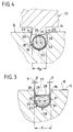
- a press plate 21 provided at the lower end of a press ram (not shown) of a hydraulic press has a press rib 22 which is adapted to the longitudinal profile (see FIG. 1) of the receiving groove 20 and which can dip into the receiving groove 20 with play on both sides and when it continues to fall, the Pipe wall 23 of the tubular heater 18 deformed visually.
- a flat groove inner surface 26 is connected on both sides to the semicircular base region of the receiving groove 20 with the inner diameter A I. Both groove surfaces 26 are inclined towards each other towards the groove opening 27 and form an angle ⁇ of 4.8 ° in the present case with the perpendicular N to the wide surface B of the steel plate 11.
- the undercut of the receiving groove 20 formed by the inward inclination of the flat groove inner surfaces 26 is sufficient to hold the tubular heating element 18, the upwardly facing region 28 of which is flattened by the deformation, securely pressed against the groove inner surface 25.
- the permanently deformed tubular heating element 18 can press against the undercut surfaces 26 forming an abutment with an elastic resetting dimension that remains.
- An additional pressure holder is used in the direction of the tubular heating element 18, in places in some notches deformed areas 29, which press against the deformed tubular heating element 18 from above approximately in the area of the flattening 28.
- the tubular heater 18 contains a heating coil 30, 31, which is embedded in magnesium oxide powder 32.
- the deformation of the tubular heater from the state according to FIG. 4 to the final state according to FIG. 3 is accompanied by a substantial additional compression of the magnesium oxide embedding, so that the heating coils 30, 31 are more reliably protected than before against harmful vibrations induced by the mains frequency with improved heat transfer .
- hot runner blocks 10 can be provided on a wide area B or on both wide areas B, each with a receiving groove 20 or with a plurality of receiving grooves 20 with a corresponding number of tubular heating elements 18.
Landscapes
- Engineering & Computer Science (AREA)
- Manufacturing & Machinery (AREA)
- Mechanical Engineering (AREA)
- Moulds For Moulding Plastics Or The Like (AREA)
- Injection Moulding Of Plastics Or The Like (AREA)
- Compositions Of Macromolecular Compounds (AREA)
Claims (5)
- Bloc à canal (10) chauffant, pour un outil de moulage par injection destiné à mouler des masses plastiques, en particulier pour un outil de moulage par injection de matière plastique, le bloc à canal chaud (10) présentant, pour assurer la fixation de chaque corps chauffant tubulaire (18) sur au moins une face large (B), au moins une rainure de réception (20) ayant au fond de rainure une section transversale à peu près en demi-cercle, à laquelle se raccordent des zones de surface intérieure de rainure (26) planes, orientées vers l'ouverture de rainure (27), la section transversale à peu près en demi-cercle étant surdimensionnée par rapport au volume occupé par le corps chauffant tubulaire (18) non encore déformé,
caractérisé en ce que le corps chauffant tubulaire (18) est pressé à l'intérieur de la rainure de réception (20) et sa paroi tubulaire (23) alors déformée épouse la forme des faces de rainure (26) en contre-dépouille, en suivant (en 25) la face intérieure de rainure et est pressé, jusqu'à ce que toute la surface soit appliquée, les faces de rainure en contre-dépouille étant constituées par les zones de face intérieure de rainure (26) planes inclinées (en β) les unes vers les autres, en direction de l'ouverture de rainure (27). - Bloc à canal chaud selon la revendication 1,
caractérisé en ce que des zones de matériaux (29), délimitant latéralement l'ouverture de rainure (27), en des endroits se suivant de façon espacée, orientées en direction du corps chauffant tubulaire (18), sont soumises à une déformation permanente et maintiennent ces corps chauffants tubulaires (18) à leur position pressée sur toute la surface. - Bloc à canal chauffant selon l'une des revendications précédentes,
caractérisé en ce que la paroi tubulaire est constituée par un tube intérieur en acier inoxydable et un tube extérieur en cuivre, entourant le tube intérieur, avec contact sur toute sa surface. - Bloc à canal chaud selon l'une des revendications précédentes,
caractérisé en ce que les zones de face intérieure de rainure (26) planes forment un angle (β) de 4,8° par rapport à la perpendiculaire (N) à la face large (B). - Procédé de fabrication d'un bloc à canal chaud (10) selon les revendications 1 à 3,
selon lequel un corps tubulaire chauffant (18) est adapté à l'allure d'une rainure de réception (20) située du côté du bloc à canal chaud, le corps chauffant tubulaire (18) est inséré dans la rainure de réception (20) et y est fixé, le corps chauffant tubulaire (18) étant déformé plastiquement à l'aide d'une pression exercée mécaniquement et le corps chauffant tubulaire (18) étant alors comprimé à l'intérieur de la rainure de réception (20), ceci s'accompagnant d'une modification de sa section transversale, la présente déformation étant transmise simultanément au corps chauffant tubulaire (18) au moyen d'une plaque de pressage (21) rigide en flexion, une nervure de pressage (22), adaptée à l'allure longitudinale de la rainure de réception (20), pénétrant, avec un jeu (s) de part et d'autre, dans la rainure de réception (20) et le corps chauffant (18) étant alors déformé plastiquement.
Applications Claiming Priority (2)
| Application Number | Priority Date | Filing Date | Title |
|---|---|---|---|
| DE3935856 | 1989-10-27 | ||
| DE3935856A DE3935856C1 (fr) | 1989-10-27 | 1989-10-27 |
Publications (3)
| Publication Number | Publication Date |
|---|---|
| EP0425981A2 EP0425981A2 (fr) | 1991-05-08 |
| EP0425981A3 EP0425981A3 (en) | 1991-12-11 |
| EP0425981B1 true EP0425981B1 (fr) | 1994-12-21 |
Family
ID=6392384
Family Applications (1)
| Application Number | Title | Priority Date | Filing Date |
|---|---|---|---|
| EP90120304A Expired - Lifetime EP0425981B1 (fr) | 1989-10-27 | 1990-10-23 | Bloc à canaux de chauffe |
Country Status (3)
| Country | Link |
|---|---|
| EP (1) | EP0425981B1 (fr) |
| AT (1) | ATE115905T1 (fr) |
| DE (1) | DE3935856C1 (fr) |
Cited By (4)
| Publication number | Priority date | Publication date | Assignee | Title |
|---|---|---|---|---|
| DE19815589A1 (de) * | 1998-04-08 | 1999-10-14 | Dangelmaier Sfr Formbau | Vorrichtung zum Einpressen eines Rohrheizkörpers in eine Aufnahmenut eines Heißkanalblocks eines Kunststoffspritzgießwerkzeugs und Verfahren zur Herstellung einer Preßrippe |
| DE19845597C1 (de) * | 1998-10-05 | 1999-11-11 | Dangelmaier Sfr Formbau | Vorrichtung zum Einpressen eines Rohrheizkörpers in eine Aufnahmenut eines Heißkanalblocks eines Kunststoffspritzgießwerkzeugs o. dgl. |
| DE19845596C1 (de) * | 1998-10-05 | 1999-11-11 | Dangelmaier Sfr Formbau | Verfahren zur Herstellung eines elektrisch beheizbaren Werkzeugelements eines Kunststoffspritzgießwerkzeugs o. dgl. wie z. B. eines Heißkanalblocks |
| CN102903396A (zh) * | 2011-07-26 | 2013-01-30 | 奇鋐科技股份有限公司 | 散热单元结构及其制造方法 |
Families Citing this family (11)
| Publication number | Priority date | Publication date | Assignee | Title |
|---|---|---|---|---|
| DE4418828C5 (de) * | 1992-12-16 | 2010-05-20 | Hotset Heizpatronen U. Zubehör Gmbh | Elektrischer Heizkörper für Spritzgießwerkzeuge |
| DE4447572C5 (de) * | 1994-05-30 | 2010-04-22 | Hotset Heizpatronen U. Zubehör Gmbh | Elektrischer Heizkörper für Spritzgießwerkzeuge |
| DE4242505C2 (de) * | 1992-12-16 | 1995-07-27 | Hotset Heizpatronen Zubehoer | Elektrischer Heizkörper für Spritzgießwerkzeuge |
| FR2734756B1 (fr) * | 1995-05-30 | 1997-09-12 | Atek Dev | Ensemble d'injection pour un moule d'injection de matiere plastique ainsi qu'un procede de realisation d'un tel ensemble |
| FR2734755A1 (fr) * | 1995-05-30 | 1996-12-06 | Atek Dev | Ensemble d'injection pour un moule d'injection de matiere plastique ainsi qu'un procede de realisation d'un tel ensemble |
| CA2152664C (fr) * | 1995-06-26 | 2008-10-14 | Jobst Ulrich Gellert | Cone de moulage par injection a element chauffant insere a la presse et col d'une seule piece |
| US6099292A (en) * | 1997-10-22 | 2000-08-08 | Caco Pacific Corporation | Heater block with unitized removable heat conductive member |
| US6675055B1 (en) | 2000-06-16 | 2004-01-06 | Mold Masters Ltd. | Method and apparatus for an automated injection molding configuring and manufacturing system |
| DE10192746C5 (de) * | 2000-06-16 | 2009-10-29 | Mold-Masters (2007) Limited, Georgetown | Verfahren zum schnellen Herstellen und Montieren von Heißläufersystemen |
| CA2311829A1 (fr) † | 2000-06-16 | 2001-12-16 | Jonathon Fischer | Buse d'injection a chaud en equilibre thermique |
| DE102012106667B3 (de) | 2012-07-23 | 2013-07-25 | Heraeus Noblelight Gmbh | Vorrichtung zur Bestrahlung eines Substrats |
Family Cites Families (7)
| Publication number | Priority date | Publication date | Assignee | Title |
|---|---|---|---|---|
| US2036788A (en) * | 1934-03-06 | 1936-04-07 | Gen Electric | Electric heating unit |
| US3110796A (en) * | 1960-07-15 | 1963-11-12 | Gen Motors Corp | Cooking unit |
| US3275801A (en) * | 1964-06-17 | 1966-09-27 | Walter A Churchill | Electrical heat exchanger |
| AT308258B (de) * | 1972-01-12 | 1973-06-25 | Bleckmann & Co | Elektrischer Rohrheizkörper |
| DE2347090C3 (de) * | 1973-09-19 | 1979-01-04 | Hasco-Normalien Hasenclever & Co, 5880 Luedenscheid | Anordnung eines Widerstands-Heizelements in einer Bohrung eines zu beheizenden Werkstücks |
| DE3046471A1 (de) * | 1980-12-10 | 1982-07-22 | Bernhard 7410 Reutlingen Dangelmaier | Duesenkern zum einbau in einen duesenkoerper von heisskanalspritzduesen fuer eine kunststoffspritzgiessvorrichtung |
| DE3644523A1 (de) * | 1986-09-25 | 1988-07-14 | Agfa Gevaert Ag | Verfahren zur herstellung eines spritzgiesswerkzeuges |
-
1989
- 1989-10-27 DE DE3935856A patent/DE3935856C1/de not_active Expired - Fee Related
-
1990
- 1990-10-23 AT AT90120304T patent/ATE115905T1/de not_active IP Right Cessation
- 1990-10-23 EP EP90120304A patent/EP0425981B1/fr not_active Expired - Lifetime
Cited By (6)
| Publication number | Priority date | Publication date | Assignee | Title |
|---|---|---|---|---|
| DE19815589A1 (de) * | 1998-04-08 | 1999-10-14 | Dangelmaier Sfr Formbau | Vorrichtung zum Einpressen eines Rohrheizkörpers in eine Aufnahmenut eines Heißkanalblocks eines Kunststoffspritzgießwerkzeugs und Verfahren zur Herstellung einer Preßrippe |
| DE19815589C2 (de) * | 1998-04-08 | 2000-12-14 | Dangelmaier Sfr Formbau | Vorrichtung zum Einpressen eines Rohrheizkörpers in eine mindestens teilweise bogenförmige durchgehende Aufnahmenut eines Heißkanalblocks eines Kunststoffspritzgießwerkzeugs und Verfahren zur Herstellung einer Preßrippe |
| DE19845597C1 (de) * | 1998-10-05 | 1999-11-11 | Dangelmaier Sfr Formbau | Vorrichtung zum Einpressen eines Rohrheizkörpers in eine Aufnahmenut eines Heißkanalblocks eines Kunststoffspritzgießwerkzeugs o. dgl. |
| DE19845596C1 (de) * | 1998-10-05 | 1999-11-11 | Dangelmaier Sfr Formbau | Verfahren zur Herstellung eines elektrisch beheizbaren Werkzeugelements eines Kunststoffspritzgießwerkzeugs o. dgl. wie z. B. eines Heißkanalblocks |
| CN102903396A (zh) * | 2011-07-26 | 2013-01-30 | 奇鋐科技股份有限公司 | 散热单元结构及其制造方法 |
| CN102903396B (zh) * | 2011-07-26 | 2016-05-11 | 奇鋐科技股份有限公司 | 散热单元结构及其制造方法 |
Also Published As
| Publication number | Publication date |
|---|---|
| DE3935856C1 (fr) | 1991-04-25 |
| EP0425981A3 (en) | 1991-12-11 |
| ATE115905T1 (de) | 1995-01-15 |
| EP0425981A2 (fr) | 1991-05-08 |
Similar Documents
| Publication | Publication Date | Title |
|---|---|---|
| EP0425981B1 (fr) | Bloc à canaux de chauffe | |
| DE3523826C2 (de) | Geheizte Spritzgußdüse mit eingelötetem Heizelement und Verfahren zu deren Herstellung | |
| DE60114275T2 (de) | Verfahren zur Herstellung eines verstärkten thermoplastischen Werkstücks und Form | |
| DE2519932A1 (de) | Spritzgussvorrichtung fuer kunststoff | |
| EP0261523B1 (fr) | Méthode de fabrication d'un outil de moulage par injection | |
| EP0832705A2 (fr) | Moulage d'objet en alliage léger à parois minces, fabriqué par coulée sous pression comme élément de structure pour des carrosseries | |
| DE102004046532B4 (de) | Verfahren zum Herstellen eines Kühlmantel-Abstandselements | |
| DE19731214A1 (de) | Verfahren zur Herstellung einer Spritzgußdüse unter Verwendung eines Positionierungs- und Abdichtendstückes | |
| EP2007546A1 (fr) | Ensemble corps de buse de moulage par injection et procédé de réalisation d'un ensemble corps de buse de moulage par injection | |
| DE19508952C2 (de) | Preßvorrichtung zur Erzeugung eines Formteils und entsprechendes Formteil | |
| DE19542236C2 (de) | Verfahren zum Herstellen eines Druckguß-Verteilers mit einem ein Winkelstück enthaltenden Schmelzedurchlaß | |
| DE10329380A1 (de) | Spritzgießverfahren zur Herstellung eines Gussteils | |
| DE2118000A1 (de) | Trockenelektrolytkondensator und Verfahren zu seiner Herstellung | |
| DE2824971C2 (de) | Düse für eine Kunststoffspritzgießmaschine oder Kunststoffspritzgießform mit beheizbarer Angußdüse | |
| DE10138599B4 (de) | Verfahren zur Befestigung eines Heizdrahts in einem Verteiler einer Spritzgussmaschine | |
| DE2353334A1 (de) | Verfahren zum herstellen von batterieanschlusspolen aus metall und nach dem verfahren hergestellter anschlusspol | |
| DE4114932A1 (de) | Schmelze-verteilerstueck fuer eine spritzgiesseinrichtung | |
| DE3143748C2 (de) | Form zum Spritzgießen oder Preßspritzen von Kautschuk oder anderen plastischen, wärmehärtbaren Werkstoffen | |
| EP0700766B1 (fr) | Dispositif pour fabriquer des articles moulés par injection | |
| EP0777093B1 (fr) | Méthode pour la manufacture d'inserts et d'enrobages | |
| EP0966345B1 (fr) | Procede de fabrication de corps creux en matiere plastique | |
| DE3118793C2 (fr) | ||
| EP1204516A1 (fr) | Procede de realisation d'un corps creux par la technique de moulage a noyau fusible | |
| DE3812740A1 (de) | Giess-schmiede-verfahren | |
| DE19815589C2 (de) | Vorrichtung zum Einpressen eines Rohrheizkörpers in eine mindestens teilweise bogenförmige durchgehende Aufnahmenut eines Heißkanalblocks eines Kunststoffspritzgießwerkzeugs und Verfahren zur Herstellung einer Preßrippe |
Legal Events
| Date | Code | Title | Description |
|---|---|---|---|
| PUAI | Public reference made under article 153(3) epc to a published international application that has entered the european phase |
Free format text: ORIGINAL CODE: 0009012 |
|
| AK | Designated contracting states |
Kind code of ref document: A2 Designated state(s): AT BE CH DE DK ES FR GB GR IT LI LU NL SE |
|
| PUAL | Search report despatched |
Free format text: ORIGINAL CODE: 0009013 |
|
| AK | Designated contracting states |
Kind code of ref document: A3 Designated state(s): AT BE CH DE DK ES FR GB GR IT LI LU NL SE |
|
| 17P | Request for examination filed |
Effective date: 19911107 |
|
| 17Q | First examination report despatched |
Effective date: 19930601 |
|
| RBV | Designated contracting states (corrected) |
Designated state(s): AT CH FR GB LI NL SE |
|
| REG | Reference to a national code |
Ref country code: DE Ref legal event code: 8566 |
|
| GRAA | (expected) grant |
Free format text: ORIGINAL CODE: 0009210 |
|
| AK | Designated contracting states |
Kind code of ref document: B1 Designated state(s): AT CH FR GB LI NL SE |
|
| REF | Corresponds to: |
Ref document number: 115905 Country of ref document: AT Date of ref document: 19950115 Kind code of ref document: T |
|
| EAL | Se: european patent in force in sweden |
Ref document number: 90120304.2 |
|
| GBT | Gb: translation of ep patent filed (gb section 77(6)(a)/1977) |
Effective date: 19950117 |
|
| ET | Fr: translation filed | ||
| PLBI | Opposition filed |
Free format text: ORIGINAL CODE: 0009260 |
|
| 26 | Opposition filed |
Opponent name: JOBST, ULRICH, GELLERT Effective date: 19950921 |
|
| NLR1 | Nl: opposition has been filed with the epo |
Opponent name: JOBST, ULRICH, GELLERT |
|
| PLBF | Reply of patent proprietor to notice(s) of opposition |
Free format text: ORIGINAL CODE: EPIDOS OBSO |
|
| PLBF | Reply of patent proprietor to notice(s) of opposition |
Free format text: ORIGINAL CODE: EPIDOS OBSO |
|
| PLBO | Opposition rejected |
Free format text: ORIGINAL CODE: EPIDOS REJO |
|
| PLBN | Opposition rejected |
Free format text: ORIGINAL CODE: 0009273 |
|
| STAA | Information on the status of an ep patent application or granted ep patent |
Free format text: STATUS: OPPOSITION REJECTED |
|
| 27O | Opposition rejected |
Effective date: 19970923 |
|
| NLR2 | Nl: decision of opposition | ||
| REG | Reference to a national code |
Ref country code: CH Ref legal event code: PFA Free format text: SFR FORMENBAU DANGELMAIER GMBH TRANSFER- SFR FORMENBAU GMBH |
|
| NLT1 | Nl: modifications of names registered in virtue of documents presented to the patent office pursuant to art. 16 a, paragraph 1 |
Owner name: SFR FORMENBAU GMBH |
|
| REG | Reference to a national code |
Ref country code: FR Ref legal event code: CA Ref country code: FR Ref legal event code: CD |
|
| REG | Reference to a national code |
Ref country code: GB Ref legal event code: IF02 |
|
| PGFP | Annual fee paid to national office [announced via postgrant information from national office to epo] |
Ref country code: NL Payment date: 20071031 Year of fee payment: 18 |
|
| PGFP | Annual fee paid to national office [announced via postgrant information from national office to epo] |
Ref country code: AT Payment date: 20071025 Year of fee payment: 18 Ref country code: CH Payment date: 20071105 Year of fee payment: 18 |
|
| PGFP | Annual fee paid to national office [announced via postgrant information from national office to epo] |
Ref country code: SE Payment date: 20071017 Year of fee payment: 18 |
|
| PGFP | Annual fee paid to national office [announced via postgrant information from national office to epo] |
Ref country code: FR Payment date: 20071023 Year of fee payment: 18 Ref country code: GB Payment date: 20071011 Year of fee payment: 18 |
|
| REG | Reference to a national code |
Ref country code: CH Ref legal event code: PL |
|
| EUG | Se: european patent has lapsed | ||
| GBPC | Gb: european patent ceased through non-payment of renewal fee |
Effective date: 20081023 |
|
| NLV4 | Nl: lapsed or anulled due to non-payment of the annual fee |
Effective date: 20090501 |
|
| REG | Reference to a national code |
Ref country code: FR Ref legal event code: ST Effective date: 20090630 |
|
| PG25 | Lapsed in a contracting state [announced via postgrant information from national office to epo] |
Ref country code: NL Free format text: LAPSE BECAUSE OF NON-PAYMENT OF DUE FEES Effective date: 20090501 |
|
| PG25 | Lapsed in a contracting state [announced via postgrant information from national office to epo] |
Ref country code: AT Free format text: LAPSE BECAUSE OF NON-PAYMENT OF DUE FEES Effective date: 20081023 |
|
| PG25 | Lapsed in a contracting state [announced via postgrant information from national office to epo] |
Ref country code: CH Free format text: LAPSE BECAUSE OF NON-PAYMENT OF DUE FEES Effective date: 20081031 Ref country code: FR Free format text: LAPSE BECAUSE OF NON-PAYMENT OF DUE FEES Effective date: 20081031 Ref country code: LI Free format text: LAPSE BECAUSE OF NON-PAYMENT OF DUE FEES Effective date: 20081031 |
|
| PG25 | Lapsed in a contracting state [announced via postgrant information from national office to epo] |
Ref country code: GB Free format text: LAPSE BECAUSE OF NON-PAYMENT OF DUE FEES Effective date: 20081023 |
|
| PG25 | Lapsed in a contracting state [announced via postgrant information from national office to epo] |
Ref country code: SE Free format text: LAPSE BECAUSE OF NON-PAYMENT OF DUE FEES Effective date: 20081024 |