EP0425981B1 - Hot runner block - Google Patents
Hot runner block Download PDFInfo
- Publication number
- EP0425981B1 EP0425981B1 EP90120304A EP90120304A EP0425981B1 EP 0425981 B1 EP0425981 B1 EP 0425981B1 EP 90120304 A EP90120304 A EP 90120304A EP 90120304 A EP90120304 A EP 90120304A EP 0425981 B1 EP0425981 B1 EP 0425981B1
- Authority
- EP
- European Patent Office
- Prior art keywords
- groove
- heating element
- tubular heating
- hot runner
- runner unit
- Prior art date
- Legal status (The legal status is an assumption and is not a legal conclusion. Google has not performed a legal analysis and makes no representation as to the accuracy of the status listed.)
- Expired - Lifetime
Links
- 238000010438 heat treatment Methods 0.000 claims abstract description 53
- 229920003023 plastic Polymers 0.000 claims abstract description 10
- 239000004033 plastic Substances 0.000 claims abstract description 10
- 239000000463 material Substances 0.000 claims abstract description 5
- RYGMFSIKBFXOCR-UHFFFAOYSA-N Copper Chemical compound [Cu] RYGMFSIKBFXOCR-UHFFFAOYSA-N 0.000 claims description 5
- 150000001875 compounds Chemical class 0.000 claims description 5
- 229910052802 copper Inorganic materials 0.000 claims description 5
- 239000010949 copper Substances 0.000 claims description 5
- 238000001746 injection moulding Methods 0.000 claims description 4
- 238000000034 method Methods 0.000 claims description 4
- 238000003825 pressing Methods 0.000 claims description 4
- 239000010935 stainless steel Substances 0.000 claims description 4
- 229910001220 stainless steel Inorganic materials 0.000 claims description 4
- 238000002347 injection Methods 0.000 abstract description 4
- 239000007924 injection Substances 0.000 abstract description 4
- 238000009434 installation Methods 0.000 abstract 1
- 238000007493 shaping process Methods 0.000 abstract 1
- 229920002994 synthetic fiber Polymers 0.000 abstract 1
- 239000004568 cement Substances 0.000 description 4
- 230000006835 compression Effects 0.000 description 4
- 238000007906 compression Methods 0.000 description 4
- CPLXHLVBOLITMK-UHFFFAOYSA-N magnesium oxide Inorganic materials [Mg]=O CPLXHLVBOLITMK-UHFFFAOYSA-N 0.000 description 4
- 239000000395 magnesium oxide Substances 0.000 description 4
- AXZKOIWUVFPNLO-UHFFFAOYSA-N magnesium;oxygen(2-) Chemical compound [O-2].[Mg+2] AXZKOIWUVFPNLO-UHFFFAOYSA-N 0.000 description 4
- 238000009413 insulation Methods 0.000 description 3
- 229910052751 metal Inorganic materials 0.000 description 3
- 239000002184 metal Substances 0.000 description 3
- 229910000831 Steel Inorganic materials 0.000 description 2
- 239000003795 chemical substances by application Substances 0.000 description 2
- 239000004020 conductor Substances 0.000 description 2
- 238000004382 potting Methods 0.000 description 2
- 239000000843 powder Substances 0.000 description 2
- 239000007921 spray Substances 0.000 description 2
- 239000010959 steel Substances 0.000 description 2
- 229910000881 Cu alloy Inorganic materials 0.000 description 1
- CWYNVVGOOAEACU-UHFFFAOYSA-N Fe2+ Chemical compound [Fe+2] CWYNVVGOOAEACU-UHFFFAOYSA-N 0.000 description 1
- 230000006978 adaptation Effects 0.000 description 1
- 229910052782 aluminium Inorganic materials 0.000 description 1
- XAGFODPZIPBFFR-UHFFFAOYSA-N aluminium Chemical compound [Al] XAGFODPZIPBFFR-UHFFFAOYSA-N 0.000 description 1
- 238000005266 casting Methods 0.000 description 1
- 238000010276 construction Methods 0.000 description 1
- 230000007547 defect Effects 0.000 description 1
- 238000009826 distribution Methods 0.000 description 1
- 229920006351 engineering plastic Polymers 0.000 description 1
- 230000001771 impaired effect Effects 0.000 description 1
- 238000007373 indentation Methods 0.000 description 1
- 230000005923 long-lasting effect Effects 0.000 description 1
- 238000004519 manufacturing process Methods 0.000 description 1
- 230000010355 oscillation Effects 0.000 description 1
- 238000007789 sealing Methods 0.000 description 1
- 239000000243 solution Substances 0.000 description 1
- 230000007704 transition Effects 0.000 description 1
Images

Classifications
-
- B—PERFORMING OPERATIONS; TRANSPORTING
- B29—WORKING OF PLASTICS; WORKING OF SUBSTANCES IN A PLASTIC STATE IN GENERAL
- B29C—SHAPING OR JOINING OF PLASTICS; SHAPING OF MATERIAL IN A PLASTIC STATE, NOT OTHERWISE PROVIDED FOR; AFTER-TREATMENT OF THE SHAPED PRODUCTS, e.g. REPAIRING
- B29C45/00—Injection moulding, i.e. forcing the required volume of moulding material through a nozzle into a closed mould; Apparatus therefor
- B29C45/17—Component parts, details or accessories; Auxiliary operations
- B29C45/26—Moulds
- B29C45/27—Sprue channels ; Runner channels or runner nozzles
- B29C45/2737—Heating or cooling means therefor
- B29C45/2738—Heating or cooling means therefor specially adapted for manifolds
-
- H—ELECTRICITY
- H05—ELECTRIC TECHNIQUES NOT OTHERWISE PROVIDED FOR
- H05B—ELECTRIC HEATING; ELECTRIC LIGHT SOURCES NOT OTHERWISE PROVIDED FOR; CIRCUIT ARRANGEMENTS FOR ELECTRIC LIGHT SOURCES, IN GENERAL
- H05B3/00—Ohmic-resistance heating
- H05B3/40—Heating elements having the shape of rods or tubes
- H05B3/42—Heating elements having the shape of rods or tubes non-flexible
- H05B3/48—Heating elements having the shape of rods or tubes non-flexible heating conductor embedded in insulating material
Definitions
- the invention relates to an injection mold according to the preamble of claim 1.
- heating cartridges or tubular heating elements are used to heat a hot runner block.
- heating cartridges are only require receiving holes in the narrow sides of the hot runner block, into which the heating cartridges must be inserted individually in order to achieve a sufficient heat transfer or heat transfer.
- Circular cylindrical heating cartridges and their corresponding circular cylindrical receiving bores require a narrow sliding fit (at least H 7).
- a structurally relatively complex individual adjustment also consists in the fact that a receiving bore is centered in its plane of diameter longitudinally divided, is part of a terminal block as well as the hot runner block.
- tubular heating elements are used, for which a receiving groove is embedded in at least one broad area of a hot runner block.
- the longitudinal course of the receiving groove roughly follows the contour of the hot runner block, for example circular, cruciform, H-shaped or T-shaped in its basic form.
- the tubular heater is cast in the receiving groove either by means of a metal-containing heat-conducting cement or in a complex manner by means of a copper alloy.
- DE-A-3 046 471 describes a hot runner spray nozzle for a plastic injection mold.
- an electric tubular heating element is pressed into an outer groove (with an approximately semicircular cross section) extending on the nozzle body side by means of an outer hollow cylindrical metal jacket.
- the width of the screw groove is slightly smaller than the outside diameter of the tubular heater (see p. 14 paragraph 3). That known solution would lead to a very complex construction when applied to a hot runner block.
- the heat exchanger plate made of cast aluminum has a receiving groove for a tubular heating element.
- the receiving groove has an approximately 270 ° circular cross-section, to which two flat parallel-walled surface areas adjoin the groove opening. Below the two parallel-walled surface areas, the circular cross-section is slightly excluded to achieve an undercut, while the undeformed tubular heater in the groove base, which is a semicircular Cross-section, fits snugly.
- the tubular heating element is pressed, this results in a deformation path which is too short, which leads to the tubular heating element nestling against the receiving groove, but not to a compression of the insulation agent filling surrounding the heating wires. Too little compression of the insulation medium filling regularly results in damaging oscillation of the heating wires at the mains frequency.
- the tubular heater is hammered into the receiving groove with a hammer tool, which can lead to mechanical overloading of the heating wires.
- the invention is based on the object of designing the known hot runner block in such a way that each tubular heating element can be used quickly and without time-consuming rework can and also guarantees unchanged good heat transfer properties over its entire service life.
- this object has been achieved in that the tubular heating element is pressed within the receiving groove and its tube wall, which is deformed in the process, is nestled and held pressed against the inner surface of the groove.
- the interior of the tubular heater contains at least one heating coil made of a heating conductor material within a magnesium oxide embedding. The magnesium oxide powder is compressed and in this way distances the heating coil from the inner surface of the tubular body.
- the tubular heating element After the tubular heating element has been largely assembled, ie adapted to the course of the hot-channel block-side receiving groove and provided with electrical connections, the tubular heating element is inserted into the receiving groove.
- the receiving groove is oversized compared to the space requirement of the tubular heater.
- the tubular heating element is now deformed - expediently using a mechanical pressure tool - and at the same time pressed while changing the cross-section of the tubular body within the receiving groove.
- the deformed tube wall is pressed tightly against the inner surface of the receiving groove and pressed and held pressed in this molded position, so that an optimal uniform heat transfer is guaranteed.
- the heat transfer takes place directly from the tube wall to the groove inner surface with a very high degree of efficiency, which in comparison to the known is not affected by any potting compound.
- the deformation pressure required to press the tubular heating element is applied evenly. This can e.g. by means of a rigid press plate which has a protruding deformation rib which is largely analogous with regard to the longitudinal course and opening width of the receiving groove.
- the pressed tubular heater is held down in the position pressed against the groove inner surface by the fact that the Undercut groove and the pressed tubular heater is held pressed by the groove undercut surface against the groove inner surface.
- the tube wall is formed by an inner tube made of stainless steel (known per se) and by an outer tube made of copper which surrounds the inner tube.
- the copper outer tube is pushed onto the latter before the tube heater, which is still straight, is assembled, whereupon the resulting double tube is bent according to the course of the receiving groove and the electrical connections are made.
- the double pipe is pressed according to the invention.
- the ductile copper pipe nestles against both the outer wall of the inner pipe and the inner surface of the receiving groove.
- material areas delimiting the slot opening are permanently deformed at points successively spaced, directed towards the tubular heating element, and hold it in its pressed-on position. These deformation points can form indentations.
- the invention also relates to a method for producing a hot runner block, as can be seen from "Engineering plastics " according to the preamble of claim 5. With the inventive method according to the characterizing part of claim 1, a quick and safe pressing of the tubular heater is guaranteed.
- a hot runner block is provided with the reference number 10.
- the hot runner block 10 consists essentially of a steel or non-ferrous metal plate 11 of approximately rectangular basic shape.
- the hot runner block 10 contains a sprue bush 12 for receiving the machine-side nozzle, not shown.
- Distribution channels 13, 14, 15 lead from the sprue bush 12 to heated high-performance nozzles 16, the nozzle regions 17 of which in each case connect to a mold cavity of an injection molding tool, not shown, on the mold plate side.
- a tubular heater 18 with electrical connection units 19 is positioned in a receiving groove 20 in the following way:
- the receiving groove 20 is oversized compared to the space requirement of the tubular heating element 18, which initially has a circular cross section in the undeformed state.
- the outer diameter A R of the tubular heater is 5 mm
- the inner diameter A I of the receiving groove 20, which is semicircular in its groove base is 5.8 mm.
- a press plate 21 provided at the lower end of a press ram (not shown) of a hydraulic press has a press rib 22 which is adapted to the longitudinal profile (see FIG. 1) of the receiving groove 20 and which can dip into the receiving groove 20 with play on both sides and when it continues to fall, the Pipe wall 23 of the tubular heater 18 deformed visually.
- a flat groove inner surface 26 is connected on both sides to the semicircular base region of the receiving groove 20 with the inner diameter A I. Both groove surfaces 26 are inclined towards each other towards the groove opening 27 and form an angle ⁇ of 4.8 ° in the present case with the perpendicular N to the wide surface B of the steel plate 11.
- the undercut of the receiving groove 20 formed by the inward inclination of the flat groove inner surfaces 26 is sufficient to hold the tubular heating element 18, the upwardly facing region 28 of which is flattened by the deformation, securely pressed against the groove inner surface 25.
- the permanently deformed tubular heating element 18 can press against the undercut surfaces 26 forming an abutment with an elastic resetting dimension that remains.
- An additional pressure holder is used in the direction of the tubular heating element 18, in places in some notches deformed areas 29, which press against the deformed tubular heating element 18 from above approximately in the area of the flattening 28.
- the tubular heater 18 contains a heating coil 30, 31, which is embedded in magnesium oxide powder 32.
- the deformation of the tubular heater from the state according to FIG. 4 to the final state according to FIG. 3 is accompanied by a substantial additional compression of the magnesium oxide embedding, so that the heating coils 30, 31 are more reliably protected than before against harmful vibrations induced by the mains frequency with improved heat transfer .
- hot runner blocks 10 can be provided on a wide area B or on both wide areas B, each with a receiving groove 20 or with a plurality of receiving grooves 20 with a corresponding number of tubular heating elements 18.
Abstract
Description
Die Erfindung betrifft ein Spritzgießwerkzeug entsprechend dem Oberbegriff des Anspruchs 1.The invention relates to an injection mold according to the preamble of claim 1.
Die gebräuchlichsten Beheizungs-Arten für Heißkanal-Blöcke sind in der Reihe "Technische Kunststoffe Berechnen-Gestalten-Anwenden C.2.1" der Hoechst Aktiengesellschaft D-6230 Frankfurt am Main 80, erschienen 1981 (s. dort Seiten 18 und 19) dargestellt.The most common types of heating for hot runner blocks are shown in the "Technical Plastics Calculate-Design-Apply C.2.1" series by Hoechst Aktiengesellschaft D-6230 Frankfurt am Main 80, published in 1981 (see
Zur Beheizung eines Heißkanalblockes gelangen vornehmlich alternativ Heizpatronen oder Rohrheizkörper zur Anwendung.Alternatively, heating cartridges or tubular heating elements are used to heat a hot runner block.
Ein gewisser Vorteil von Heizpatronen besteht darin, daß diese lediglich in die Schmalseiten des Heißkanalblockes eingelassene Aufnahmebohrungen erfordern, in welche die Heizpatronen zur Erzielung eines hinreichenden Wärmedurchgangs bzw. Wärmeübergangs aber individuell genau eingesetzt werden müssen. Kreiszylindrische Heizpatronen und ihre korrespondierenden kreiszylindrischen Aufnahmebohrungen erfordern hierbei einen engen Schiebesitz (mindestens H 7).A certain advantage of heating cartridges is that they only require receiving holes in the narrow sides of the hot runner block, into which the heating cartridges must be inserted individually in order to achieve a sufficient heat transfer or heat transfer. Circular cylindrical heating cartridges and their corresponding circular cylindrical receiving bores require a narrow sliding fit (at least H 7).
Eine baulich verhältnismäßig aufwendige individuelle Anpassung besteht auch darin, daß eine Aufnahmebohrung, in ihrer Durchmesserebene mittig längsgeteilt, sowohl Bestandteil einer Klemmleiste als auch des Heißkanalblockes ist.A structurally relatively complex individual adjustment also consists in the fact that a receiving bore is centered in its plane of diameter longitudinally divided, is part of a terminal block as well as the hot runner block.
Um die individuellen Anpassungsarbeiten an den Aufnahmebohrungen zu vermeiden, ist man schließlich dazu übergegangen, gemäß der DE-PS 23 47 090 den Heizpatronenmantel und die entsprechende Aufnahmebohrung mit demselben Winkel konisch auszubilden, so daß eine satte Anlage der Heizpatronenmantelfläche an die Innenmantelfläche der Aufnahmebohrung zur Erzielung einer guten Wärmeübertragung vorhanden ist.In order to avoid the individual adaptation work on the receiving bores, it has finally become conical in accordance with DE-PS 23 47 090 to design the heating cartridge jacket and the corresponding receiving bore with the same angle, so that the heating cartridge jacket surface fits snugly against the inner lateral surface of the receiving bore to achieve this good heat transfer is present.
Für den Fall, daß ein Heißkanalblock wegen eines nur mit engen Temperaturtoleranzen zu verarbeitenden Kunststoffes besonders gleichmäßig beheizt werden muß, werden Rohrheizkörper verwendet, für welche an mindestens einer Breitfläche eines Heißkanalblocks eine Aufnahmenut eingelassen ist. Der Längsverlauf der Aufnahmenut folgt hierbei in etwa der Kontur des in seiner Grundform beispielsweise kreisförmigen, kreuzförmigen, H-förmigen oder T-förmigen Heißkanalblockes. Der Rohrheizkörper ist in der Aufnahmenut entweder mittels eines metallhaltigen Wärmeleitzements oder in aufwendiger Weise mittels einer Kupferlegierung eingegossen. Eine gleichmäßige Wärmeübertragung vom Rohrheizkörper auf den Heißkanalblock ist hierbei aber nur dann möglich, wenn sich über die Länge des Rohrheizkörpers keine Stör- bzw. Unstetigkeitsstellen im Übergang Rohrheizkörper/Wärmeleitzement bzw. Vergußmasse/Innenfläche der Aufnahmenut ergeben. Für den Fall, daß die Vergußmasse Lunker (Luftblasen) enthält, sind der Wärmedurchgang bzw. der Wärmeübergang an solchen Stellen beeinträchtigt. Es ist deshalb wichtig, daß z.B. Wärmeleitzement bei der Befestigung des Rohrheizkörpers schichtweise eingebracht wird, was eine langwierige Prozedur bedeutet, wie aus einer Verarbeitungsanleitung aus 4/81 der Firma G. Huetter, D-8990 Lindau, ersichtlich ist.In the event that a hot runner block has to be heated particularly evenly because of a plastic that can only be processed with narrow temperature tolerances, tubular heating elements are used, for which a receiving groove is embedded in at least one broad area of a hot runner block. The longitudinal course of the receiving groove roughly follows the contour of the hot runner block, for example circular, cruciform, H-shaped or T-shaped in its basic form. The tubular heater is cast in the receiving groove either by means of a metal-containing heat-conducting cement or in a complex manner by means of a copper alloy. Even heat transfer from the tubular heater to the hot runner block is only possible if there are no defects or discontinuities along the length of the tubular heater in the transition from tubular heater / heat-conducting cement or potting compound / inner surface the receiving groove result. In the event that the casting compound contains cavities (air bubbles), the heat transfer or the heat transfer at such points are impaired. It is therefore important that, for example, heat-conducting cement is applied in layers when fastening the tubular heating element, which means a lengthy procedure, as can be seen from a processing instruction from 4/81 from G. Huetter, D-8990 Lindau.
Bei unsachgemäßer Anwendung oder bei lange anhaltender Wärme-Wechselbelastung ist außerdem nicht auszuschließen, daß zwischen der Vergußmasse (z.B Wärmeleitzement) und der Aufnahmenut Spalten bzw. Abrisse entstehen, welche die Wärmeübertragung deutlich herabsetzen. Für den Fall, daß derartige Spalten oder Abrisse nur stellenweise auftreten, ist eine ungleichmäßige Wärmeübertragung die Folge.In the event of improper use or in the event of long-lasting alternating heat loads, it cannot be ruled out that gaps or tears occur between the sealing compound (eg heat-conducting cement) and the receiving groove, which significantly reduce the heat transfer. In the event that such gaps or breaks occur only in places, an uneven heat transfer is the result.
Mit der Literaturstelle aus "Technische Kunststoffe ..." ist im wesentlichen vergleichbar mit die EP-A-0 262 490.The reference from "Technical plastics ..." is essentially comparable to EP-A-0 262 490.
In der DE-A-3 046 471 ist eine Heißkanalspritzdüse für ein Kunststoffspritzgießwerkzeug beschrieben. Bei der bekannten Heißkanalspritzdüse wird ein elektrischer Rohrheizkörper mittels eines äußeren hohlzylindrischen Metallmantels in eine sich schraubenlinienförmig erstreckende düsenkörperseitige Außennut (mit etwa halbkreisförmigem Querschnitt) hineingepreßt. Hierbei ist die Weite der Schraubennut geringfügig kleiner als der Außendurchmesser des Rohrheizkörpers (s. S. 14 Abs. 3). Jene bekannte Lösung würde bei Anwendung auf einen Heißkanalblock zu einer sehr aufwendigen Bauweise führen.DE-A-3 046 471 describes a hot runner spray nozzle for a plastic injection mold. In the known hot runner spray nozzle, an electric tubular heating element is pressed into an outer groove (with an approximately semicircular cross section) extending on the nozzle body side by means of an outer hollow cylindrical metal jacket. The width of the screw groove is slightly smaller than the outside diameter of the tubular heater (see p. 14 paragraph 3). That known solution would lead to a very complex construction when applied to a hot runner block.
Von der FR-A-2 167 674 ist es bekannt, für einen mit einem elektrischen Heizdraht ausgestatteten Rohrheizkörper ein doppellagiges Rohr zu verwenden, dessen Außenrohr aus rostfreiem Stahl und dessen Innenrohr aus Kupfer besteht. Ein ähnliches Zweilagenrohr aus unterschiedlichen Werkstoffen eines Rohrheizkörpers ist in der US-A-2 036 788 beschrieben.From FR-A-2 167 674 it is known to use a double-layer tube for a tubular heating element equipped with an electrical heating wire, the outer tube of which is made of stainless steel and the inner tube of which is copper. A similar two-layer pipe made of different materials of a tubular heater is described in US-A-2 036 788.
Von der US-A-3 275 801 ist ein elektrischer Wärmetauscher bekannt, dessen aus Aluminiumguß bestehende Wärmetauscherplatte eine Aufnahmenut für einen Rohrheizkörper aufweist. Die Aufnahmenut besitzt einen sich etwa über 270° erstreckenden kreisförmigen Querschnitt, an welchen sich benachbart der Nutöffnung zwei ebene parallelwandige Flächenbereiche anschließen. Unterhalb der beiden parallelwandigen Flächenbereiche ist der Kreisquerschnitt zur Erzielung einer Hinterschneidung geringfügig ausgenommen, während der unverformte Rohrheizkörper in Nutgrund, der einen halbkreisförmigen Querschnitt aufweist, satt einliegt. Dieses hat beim Verpressen des Rohrheizkörpers einen zu geringen Verformungsweg zur Folge, was zwar zu einem Anschmiegen des Rohrheizkörpers an die Aufnahmenut, nicht aber zu einer Verdichtung der die Heizdrähte umgebenden Isolationsmittel-Füllung führt. Eine zu geringe Verdichtung der Isolationsmittel-Füllung hat jedoch bei Netzfrequenz regelmäßig ein schädliches Schwingen der Heizdrähte zur Folge.From US-A-3 275 801 an electrical heat exchanger is known, the heat exchanger plate made of cast aluminum has a receiving groove for a tubular heating element. The receiving groove has an approximately 270 ° circular cross-section, to which two flat parallel-walled surface areas adjoin the groove opening. Below the two parallel-walled surface areas, the circular cross-section is slightly excluded to achieve an undercut, while the undeformed tubular heater in the groove base, which is a semicircular Cross-section, fits snugly. When the tubular heating element is pressed, this results in a deformation path which is too short, which leads to the tubular heating element nestling against the receiving groove, but not to a compression of the insulation agent filling surrounding the heating wires. Too little compression of the insulation medium filling regularly results in damaging oscillation of the heating wires at the mains frequency.
Im übrigen wird gemäß der US-A-3 275 801 der Rohrheizkörper mit einem Hammerwerkzeug in die Aufnahmenut eingeschlagen, was zu einer mechanischen Überbeanspruchung der Heizdrähte führen kann.In addition, according to US-A-3 275 801, the tubular heater is hammered into the receiving groove with a hammer tool, which can lead to mechanical overloading of the heating wires.
Auch bei einer elektrischen Kochplatte gemäß der US-A-3 110 796 ist ein Rohrheizleiter in einer Aufnahmenut kreisförmigen Querschnittes satt aufgenommen. Zur Halterung des Rohrheizkörpers in der Aufnahmenut wird lediglich der obere Bereich der Aufnahmenut mittels eines Preßwerkzeuges von außen zugedrückt, so daß die beabsichtigte Verdichtung der Isolationsmittel-Füllung keinesfalls hinreicht.In the case of an electric hotplate according to US Pat. No. 3,110,796, a tubular heating conductor is well received in a receiving groove of circular cross section. To hold the tubular heating element in the receiving groove, only the upper region of the receiving groove is pressed from the outside by means of a pressing tool, so that the intended compression of the insulation agent filling is in no way sufficient.
Ausgehend von dem eingangs beschriebenen bekannten Spritzgießwerkzeug dieser Gattung (s.a.a.O. "Technische Kunststoffe.." Seite 19 linke Spalte Abs. 2 ff), liegt der Erfindung die Aufgabe zugrunde, den bekannten Heißkanalblock so auszugestalten, daß jeder Rohrheizkörper rasch und ohne zeitaufwendige Nacharbeit eingesetzt werden kann und darüber hinaus über seine gesamte Standzeit unverändert gute Wärmeübertragungseigenschaften gewährleistet.Starting from the known injection molding tool of this type described above (see "Technical plastics .."
Entsprechend der Erfindung wurde diese Aufgabe dadurch gelöst, daß der Rohrheizkörper innerhalb der Aufnahmenut verpreßt und seine hierbei verformte Rohrwand gegen die Nut-Innenfläche angeschmiegt und angepreßt gehalten ist.According to the invention, this object has been achieved in that the tubular heating element is pressed within the receiving groove and its tube wall, which is deformed in the process, is nestled and held pressed against the inner surface of the groove.
Die verwendeten - an sich bekannten - Rohrheizkörper weisen regelmäßig einen kreisrunden oder abgeflacht elliptischen Rohrquerschnitt auf und bestehen aus rostfreiem Stahl. Der Innenraum des Rohrheizkörpers enthält innerhalb einer Magnesiumoxyd-Einbettung mindestens eine Heizwendel aus einem Heizleiter-Werkstoff. Das Magnesiumoxyd-Pulver ist verdichtet und distanziert auf diese Weise die Heizwendel von der Rohrkörper- Innenfläche.The tubular radiators used - known per se - regularly have a circular or flattened elliptical tube cross section and are made of stainless steel. The interior of the tubular heater contains at least one heating coil made of a heating conductor material within a magnesium oxide embedding. The magnesium oxide powder is compressed and in this way distances the heating coil from the inner surface of the tubular body.
Nachdem der Rohrheizkörper weitestgehend konfektioniert, d.h. dem Verlauf der heißkanalblockseitigen Aufnahmenut angepaßt und mit elektrischen Anschlüssen versehen, ist, wird der Rohrheizkörper in die Aufnahmenut eingelegt. Die Aufnahmenut weist gegenüber dem Raumbedarf des Rohrheizkörpers Übermaß auf. Der Rohrheizkörper wird nun - zweckmäßig mit einem mechanischen Druckwerkzeug - bildsam verformt und zugleich unter Querschnittsveränderung des Rohrkörpers innerhalb der Aufnahmenut verpreßt. Hierbei wird die verformte Rohrwand satt gegen die Innenfläche der Aufnahmenut gepreßt und angeschmiegt und in dieser angeschmiegten Position angepreßt gehalten, so daß eine optimale gleichmäßige Wärmeübertragung gewährleistet ist. Die Wärmeübertragung erfolgt hierbei unmittelbar von der Rohrwand zur Nutinnenfläche mit einem sehr hohen Wirkungsgrad, der im Vergleich zum Bekannten durch keinerlei Vergußmasse beeinträchtigt ist.After the tubular heating element has been largely assembled, ie adapted to the course of the hot-channel block-side receiving groove and provided with electrical connections, the tubular heating element is inserted into the receiving groove. The receiving groove is oversized compared to the space requirement of the tubular heater. The tubular heating element is now deformed - expediently using a mechanical pressure tool - and at the same time pressed while changing the cross-section of the tubular body within the receiving groove. Here, the deformed tube wall is pressed tightly against the inner surface of the receiving groove and pressed and held pressed in this molded position, so that an optimal uniform heat transfer is guaranteed. The heat transfer takes place directly from the tube wall to the groove inner surface with a very high degree of efficiency, which in comparison to the known is not affected by any potting compound.
Der zum Verpressen des Rohrheizkörpers erforderliche Verformungsdruck wird gleichmäßig aufgebracht. Dieses kann z.B. mittels einer biegesteifen Preßplatte geschehen, welche eine hinsichtlich Längsverlauf und Öffnungsweite der Aufnahmenut weitestgehend analoge vorstehende Verformungsrippe aufweist.The deformation pressure required to press the tubular heating element is applied evenly. This can e.g. by means of a rigid press plate which has a protruding deformation rib which is largely analogous with regard to the longitudinal course and opening width of the receiving groove.
Bei einem ca. 1000 mm langen Rohrheizkörper von 5 mm Durchmesser wurden gute Wärmeübertragungs-Ergebnisse bei einem Gesamtverformungsdruck von etwa 1000 kN erzielt.With an approx. 1000 mm long tubular heater with a 5 mm diameter, good heat transfer results were achieved with a total deformation pressure of around 1000 kN.
Es ist weiterhin wichtig, daß der verformte Rohrheizkörper in seiner an die Nut-Innenfläche angeschmiegten Lage angepreßt gehalten ist.It is also important that the deformed tubular heater is held pressed in its position nestled against the inner surface of the groove.
Das Niederhalten des verpreßten Rohrheizkörpers in der an die Nut-Innenfläche angepreßt gehaltenen Lage geschieht entsprechend weiteren Erfindungsmerkmalen zweckmäßig dadurch, daß die Aufnahmenut hinterschnitten und der verpreßte Rohrheizkörper durch die Nut- Hinterschneidungsfläche gegen die Nut-Innenfläche angepreßt gehalten ist.According to further features of the invention, the pressed tubular heater is held down in the position pressed against the groove inner surface by the fact that the Undercut groove and the pressed tubular heater is held pressed by the groove undercut surface against the groove inner surface.
Dies geschieht entsprechend der Erfindung dadurch, daß sich an dem etwa halbkreisförmigen Querschnitt der Aufnahmenut zur Nutöffnung aufeinanderzu geneigte ebene Nutflächenbereiche anschließen, welche den verpreßten Rohrheizkörper in seiner an
die Nut-Innenfläche angeschmiegten Position halten.This is done according to the invention in that adjoining the approximately semicircular cross section of the receiving groove towards the groove opening is inclined flat groove surface areas which the pressed tubular heater in its
hold the groove-inside surface snugly in position.
Für gewisse Anwendungsfälle kann es zweckmäßig sein, wenn die Rohrwand von einem Innenrohr aus rostfreiem Stahl (an sich bekannt) und von einem das Innenrohr satt umschließenden Außenrohr aus Kupfer gebildet ist. Das kupferne Außenrohr wird vor der Konfektionierung des noch geraden Rohrheizkörpers auf letzteren aufgeschoben, worauf das so entstandene Doppelrohr entsprechend dem Verlauf der Aufnahmenut gebogen und die elektrischen Anschlüsse erstellt werden. Es erfolgt sodann das erfindungsgemäße Verpressen des Doppelrohres. Hierbei schmiegt sich das duktile Kupferrohr sowohl an die Außenwand des Innenrohrs als auch an die Innenfläche der Aufnahmenut an.For certain applications, it may be expedient if the tube wall is formed by an inner tube made of stainless steel (known per se) and by an outer tube made of copper which surrounds the inner tube. The copper outer tube is pushed onto the latter before the tube heater, which is still straight, is assembled, whereupon the resulting double tube is bent according to the course of the receiving groove and the electrical connections are made. Then the double pipe is pressed according to the invention. Here, the ductile copper pipe nestles against both the outer wall of the inner pipe and the inner surface of the receiving groove.
In weiterer Ausgestaltung der Erfindung kann es überdies zweckmäßig sein, daß die Nutöffnung begrenzende Werkstoffbereiche an im Abstand aufeinander folgenden Stellen, zum Rohrheizkörper hin gerichtet, dauernd verformt sind und diesen in seiner angepreßten Lage halten. Diese Verformungsstellen können etwa Einkerbungen bilden.In a further embodiment of the invention, it may also be expedient that material areas delimiting the slot opening are permanently deformed at points successively spaced, directed towards the tubular heating element, and hold it in its pressed-on position. These deformation points can form indentations.
Die Erfindung befaßt sich außerdem mit einem Verfahren zur Herstellung eines Heißkanalblocks, wie es entsprechend dem Oberbegriff des Anspruchs 5 aus "Technische Kunststoffe..." ersichtlich ist. Mit dem erfindungsgemäßen Verfahren entsprechend dem Kennzeichenteil des Anspruchs 1 ist ein rasches und sicheres Verpressen des Rohrheizkörpers gewährleistet.The invention also relates to a method for producing a hot runner block, as can be seen from "Engineering plastics ..." according to the preamble of
In den Zeichnungen ist ein bevorzugtes Ausführungsbeispiel entsprechend der Erfindung näher dargestellt, es zeigen:
- Fig. 1 eine Draufsicht auf einen Heißkanalblock von im wesentlichen rechteckiger Grundform,
- Fig. 2 eine Längsschnittansicht gemäß der abgeknickten Schnittlinie II-II in Fig. 1,
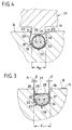
- Fig. 3 einen verformten und in der heißkanalblockseitigen Aufnahmenut gehaltenen Rohrheizkörper in vergrößerter Darstellung entsprechend dem in Fig. 2 mit III bezeichneten eingekreisten Detail, und
- Fig. 4 eine schematische Darstellung eines Rohrheizkörpers unmittelbar vor dem Verpressen.
- 1 is a plan view of a hot runner block of an essentially rectangular basic shape,
- 2 is a longitudinal sectional view according to the bent section line II-II in Fig. 1,
- Fig. 3 shows a deformed tubular heater held in the hot runner block-side receiving groove in an enlarged view corresponding to the circled detail designated III in Fig. 2, and
- Fig. 4 is a schematic representation of a tubular heater immediately before pressing.
In den Zeichnungen ist ein Heißkanalblock mit der Bezugsziffer 10 versehen. Der Heißkanalblock 10 besteht im wesentlichen aus einer Stahl- oder NE-Metallplatte 11 von etwa rechteckiger Grundform.In the drawings, a hot runner block is provided with the
Der Heißkanalblock 10 enthält eine Angußbuchse 12 zur Aufnahme der nicht dargestellten maschinenseitigen Düse. Von der Angußbuchse 12 führen Verteilerkanäle 13, 14, 15 zu beheizten Hochleistungsdüsen 16, deren Düsenbereiche 17 jeweils an eine nicht dargestellte formplattenseitige Formhöhlung eines Spritzgießwerkzeuges anschließen.The
Ein Rohrheizkörper 18 mit elektrischen Anschlußeinheiten 19 ist in einer Aufnahmenut 20 in folgender Weise positioniert:
Wie aus Fig. 4 zu ersehen, besitzt die Aufnahmenut 20 gegenüber dem Raumbedarf des im unverformten Zustand zunächst einen kreisrunden Querschnitt aufweisenden Rohrheizkörpers 18 Übermaß. So beträgt beispielsweise der Außendurchmesser AR des Rohrheizkörpers 5 mm, während der Innendurchmesser AI der in ihrem Nutgrund halbkreisförmigen Aufnahmenut 20 5,8 mm ausmacht.A
As can be seen from FIG. 4, the receiving
Eine am unteren Ende eines nicht dargestellten Preßstempels einer hydraulischen Presse vorgesehene Preßplatte 21 weist eine dem Längsverlauf (s. Fig. 1) der Aufnahmenut 20 angepaßte Preßrippe 22 auf, die mit beiderseitigem Spiel s in die Aufnahmenut 20 eintauchen kann und bei ihrem weiterem Niedergehen die Rohrwand 23 des Rohrheizkörpers 18 bildsam verformt.A
Dies geschieht derart, daß sich ein Bereich 24 der Rohrwandaußenfläche satt gegen einen Bereich 25 der Innenfläche der Nut 18 anschmiegt.This is done in such a way that an
Im Zusammenhang der Fig. 3 und 4 wird deutlich, daß sich beidseitig an den halbkreisförmigen Grundbereich der Aufnahmenut 20 mit dem Innendurchmesser AI jeweils eine ebene Nutinnenfläche 26 anschließt. Beide Nutflächen 26 sind zur Nutöffnung 27 hin aufeinanderzu geneigt und bilden mit der Senkrechten N auf die Breitfläche B der Stahlplatte 11 einen Winkel β von im vorliegenden Fall 4,8°.In connection with FIGS. 3 and 4 it is clear that a flat groove
Die durch die Einwärtsneigung der ebenen Nut-Innenflächen 26 gebildete Hinterschneidung der Aufnahmenut 20 genügt, um den Rohrheizkörper 18, dessen nach oben weisender Bereich 28 durch die Verformung abgeplattet ist, sicher gegen die Nut-Innenfläche 25 angepreßt zu halten. Hierbei kann der dauernd verformte Rohrheizkörper 18 mit einem ihm verbliebenen elastischen Rückstellmaß gegen die ein Widerlager bildenden Hinterschneidungsflächen 26 drücken.The undercut of the receiving
Einer zusätzlichen Anpreßhalterung dienen in Richtung auf den Rohrheizkörper 18 stellenweise etwa kerbenartig verformte Bereiche 29, welche von oben her etwa im Bereich der Abplattung 28 gegen den verformten Rohrheizkörper 18 drücken.An additional pressure holder is used in the direction of the
Der Rohrheizkörper 18 enthält eine Heizwendel 30, 31, die in Magnesiumoxyd-Pulver 32 eingebettet ist.The
Mit der Verformung des Rohrheizkörpers vom Zustand gemäß Fig. 4 zum endgültigen Zustand gemäß Fig. 3 geht eine wesentliche zusätzliche Verdichtung der Magnesiumoxyd-Einbettung einher, so daß die Heizwendel 30, 31 bei verbesserter Wärmeübertragung zuverlässiger als bisher gegen durch Netzfrequenz eingeleitete schädliche Schwingungen geschützt sind.The deformation of the tubular heater from the state according to FIG. 4 to the final state according to FIG. 3 is accompanied by a substantial additional compression of the magnesium oxide embedding, so that the heating coils 30, 31 are more reliably protected than before against harmful vibrations induced by the mains frequency with improved heat transfer .
Der Vollständigkeit halber sei noch erwähnt, daß Heißkanalblöcke 10 an einer Breitfläche B oder an beiden Breitflächen B mit je einer Aufnahmenut 20 oder mit mehreren Aufnahmenuten 20 mit korrespondierender Anzahl von Rohrheizkörpern 18 versehen sein können.For the sake of completeness, it should also be mentioned that hot runner blocks 10 can be provided on a wide area B or on both wide areas B, each with a receiving
Claims (5)
- A hot runner unit (10) for an injection moulding tool for processing plastic compounds, particularly for a plastics injection moulding tool, wherein, on at least one wide surface (B), the hot runner unit (10) has at least one locating groove (20) for fixing a tubular heating element (18) in each case, said locating groove (20) being of approximately semicircular cross-section in the base of the groove, to which adjoin flat inner surface regions (26) of the groove, pointing inwards towards the groove opening (27), wherein the approximately semicircular cross-section is overdimensioned with respect to the spatial requirement of the non-deformed tubular heating element (18), characterised in that the tubular heating element (18) is press moulded inside the locating groove (20) and its thereby deformed tube wall (23) is moulded and held pressed down against the inner surface of the groove (at 25) by means of groove undercut surfaces (26), wherein the groove undercut surfaces are formed by the flat inner surface regions (26) of the groove which are inclined towards one another, inwards towards the groove opening (27) (at β).
- A hot runner unit according to claim 1, characterised in that the regions of material (29), delimiting the groove opening (27) at the side, are directed inwards towards the tubular heating element (18) at points following one after another at intervals and hold said tubular heating element (18) in its pressed down position.
- A hot runner unit according to one of the preceding claims, characterised in that the tube wall is formed by an inner tube made of stainless steel and by an outer tube made of copper, tightly enclosing the inner tube.
- A hot runner unit according to one of the preceding claims, characterised in that the flat inner surface regions (26) of the groove form an angle (β) of 4.8 ° with a vertical (N) on the wide surface (B).
- A method of producing a hot runner unit (10) according to claims 1 to 3, according to which a tubular heating element (18) is adapted to the course of a locating groove (20) on the hot runner unit side, the tubular heating element (18) is placed in the locating groove (20) and is fixed therein, the tubular heating element (18) is deformed in a plastic manner with mechanically exerted pressure and the tubular heating element (18) is thereby press moulded, with a change in cross-section, inside the locating groove (20), wherein the deformation pressure is evenly transmitted by means of a flexurally rigid press platen (21) to the tubular heating element (18), wherein a pressing rib (22), adapted to the longitudinal course of the locating groove (20), penetrates into the locating groove (20) with a clearance (s) on both sides and the tubular heating element (18) is thereby deformed in a plastic manner.
Applications Claiming Priority (2)
| Application Number | Priority Date | Filing Date | Title |
|---|---|---|---|
| DE3935856A DE3935856C1 (en) | 1989-10-27 | 1989-10-27 | |
| DE3935856 | 1989-10-27 |
Publications (3)
| Publication Number | Publication Date |
|---|---|
| EP0425981A2 EP0425981A2 (en) | 1991-05-08 |
| EP0425981A3 EP0425981A3 (en) | 1991-12-11 |
| EP0425981B1 true EP0425981B1 (en) | 1994-12-21 |
Family
ID=6392384
Family Applications (1)
| Application Number | Title | Priority Date | Filing Date |
|---|---|---|---|
| EP90120304A Expired - Lifetime EP0425981B1 (en) | 1989-10-27 | 1990-10-23 | Hot runner block |
Country Status (3)
| Country | Link |
|---|---|
| EP (1) | EP0425981B1 (en) |
| AT (1) | ATE115905T1 (en) |
| DE (1) | DE3935856C1 (en) |
Cited By (4)
| Publication number | Priority date | Publication date | Assignee | Title |
|---|---|---|---|---|
| DE19815589A1 (en) * | 1998-04-08 | 1999-10-14 | Dangelmaier Sfr Formbau | Rib production method for pressing bar heater element into groove positioned at injection molding tool |
| DE19845597C1 (en) * | 1998-10-05 | 1999-11-11 | Dangelmaier Sfr Formbau | Press tool conforming tubular electrical heating element into groove of pressure injection molding machine hot channel block |
| DE19845596C1 (en) * | 1998-10-05 | 1999-11-11 | Dangelmaier Sfr Formbau | Making electrically-heated hot channel block for plastic pressure injection molding |
| CN102903396A (en) * | 2011-07-26 | 2013-01-30 | 奇鋐科技股份有限公司 | Heat dissipation cell structure and manufacturing method thereof |
Families Citing this family (11)
| Publication number | Priority date | Publication date | Assignee | Title |
|---|---|---|---|---|
| DE4418828C5 (en) * | 1992-12-16 | 2010-05-20 | Hotset Heizpatronen U. Zubehör Gmbh | Electric radiator for injection molds |
| DE4242505C2 (en) * | 1992-12-16 | 1995-07-27 | Hotset Heizpatronen Zubehoer | Electric radiator for injection molds |
| DE4447572C5 (en) * | 1994-05-30 | 2010-04-22 | Hotset Heizpatronen U. Zubehör Gmbh | Electric radiator for injection molds |
| FR2734755A1 (en) * | 1995-05-30 | 1996-12-06 | Atek Dev | Injector assembly for plastic injection mould |
| FR2734756B1 (en) * | 1995-05-30 | 1997-09-12 | Atek Dev | INJECTION ASSEMBLY FOR A PLASTIC INJECTION MOLD AND A PROCESS FOR PRODUCING SUCH AN ASSEMBLY |
| CA2152664C (en) * | 1995-06-26 | 2008-10-14 | Jobst Ulrich Gellert | Injection molding nozzle with pressed in heating element and integral collar portion |
| US6099292A (en) * | 1997-10-22 | 2000-08-08 | Caco Pacific Corporation | Heater block with unitized removable heat conductive member |
| CA2311829A1 (en) † | 2000-06-16 | 2001-12-16 | Jonathon Fischer | Thermally balanced hot runner nozzle |
| DE10165026B3 (en) * | 2000-06-16 | 2016-06-16 | Mold-Masters (2007) Limited | Method for the rapid production and assembly of customized hot runner distribution plates |
| US6675055B1 (en) | 2000-06-16 | 2004-01-06 | Mold Masters Ltd. | Method and apparatus for an automated injection molding configuring and manufacturing system |
| DE102012106667B3 (en) * | 2012-07-23 | 2013-07-25 | Heraeus Noblelight Gmbh | Device for irradiating a substrate |
Family Cites Families (7)
| Publication number | Priority date | Publication date | Assignee | Title |
|---|---|---|---|---|
| US2036788A (en) * | 1934-03-06 | 1936-04-07 | Gen Electric | Electric heating unit |
| US3110796A (en) * | 1960-07-15 | 1963-11-12 | Gen Motors Corp | Cooking unit |
| US3275801A (en) * | 1964-06-17 | 1966-09-27 | Walter A Churchill | Electrical heat exchanger |
| AT308258B (en) * | 1972-01-12 | 1973-06-25 | Bleckmann & Co | Electric tubular heater |
| DE2347090C3 (en) * | 1973-09-19 | 1979-01-04 | Hasco-Normalien Hasenclever & Co, 5880 Luedenscheid | Arrangement of a resistance heating element in a bore of a workpiece to be heated |
| DE3046471A1 (en) * | 1980-12-10 | 1982-07-22 | Bernhard 7410 Reutlingen Dangelmaier | Heated nozzle core for injection moulding machine - has helical heating element laid in groove on outer face of core |
| DE3644523A1 (en) * | 1986-09-25 | 1988-07-14 | Agfa Gevaert Ag | METHOD FOR PRODUCING AN INJECTION MOLDING TOOL |
-
1989
- 1989-10-27 DE DE3935856A patent/DE3935856C1/de not_active Expired - Fee Related
-
1990
- 1990-10-23 AT AT90120304T patent/ATE115905T1/en not_active IP Right Cessation
- 1990-10-23 EP EP90120304A patent/EP0425981B1/en not_active Expired - Lifetime
Cited By (6)
| Publication number | Priority date | Publication date | Assignee | Title |
|---|---|---|---|---|
| DE19815589A1 (en) * | 1998-04-08 | 1999-10-14 | Dangelmaier Sfr Formbau | Rib production method for pressing bar heater element into groove positioned at injection molding tool |
| DE19815589C2 (en) * | 1998-04-08 | 2000-12-14 | Dangelmaier Sfr Formbau | Device for pressing a tubular heating element into an at least partially arcuate continuous receiving groove of a hot runner block of a plastic injection mold and method for producing a press rib |
| DE19845597C1 (en) * | 1998-10-05 | 1999-11-11 | Dangelmaier Sfr Formbau | Press tool conforming tubular electrical heating element into groove of pressure injection molding machine hot channel block |
| DE19845596C1 (en) * | 1998-10-05 | 1999-11-11 | Dangelmaier Sfr Formbau | Making electrically-heated hot channel block for plastic pressure injection molding |
| CN102903396A (en) * | 2011-07-26 | 2013-01-30 | 奇鋐科技股份有限公司 | Heat dissipation cell structure and manufacturing method thereof |
| CN102903396B (en) * | 2011-07-26 | 2016-05-11 | 奇鋐科技股份有限公司 | Radiating unit structure and manufacture method thereof |
Also Published As
| Publication number | Publication date |
|---|---|
| ATE115905T1 (en) | 1995-01-15 |
| DE3935856C1 (en) | 1991-04-25 |
| EP0425981A2 (en) | 1991-05-08 |
| EP0425981A3 (en) | 1991-12-11 |
Similar Documents
| Publication | Publication Date | Title |
|---|---|---|
| EP0425981B1 (en) | Hot runner block | |
| DE3523826C2 (en) | Heated injection molding nozzle with soldered heating element and process for its production | |
| DE60114275T2 (en) | Method for producing a reinforced thermoplastic workpiece and mold | |
| DE2519932A1 (en) | INJECTION MOLDING DEVICE FOR PLASTIC | |
| EP0261523B1 (en) | Method for making an injection moulding tool | |
| EP0832705A2 (en) | Thin-walled casting made of light metal alloy, produced by die-casting as structural element for car bodies | |
| DE102004046532B4 (en) | Method for producing a cooling jacket spacer | |
| DE19731214A1 (en) | Process for manufacturing an injection molding nozzle using a positioning and sealing end piece | |
| DE19508952C2 (en) | Press device for producing a molded part and corresponding molded part | |
| DE19810470B4 (en) | Method of manufacturing a cylinder for a two-stroke internal combustion engine | |
| DE19542236C2 (en) | Method of making a die-cast manifold with a melt passage containing an elbow | |
| DE10329380A1 (en) | Injection molding process for the production of a casting | |
| DE2824971C2 (en) | Nozzle for a plastic injection molding machine or plastic injection mold with a heatable sprue nozzle | |
| DE10138599B4 (en) | Method for fixing a heating wire in a distributor of an injection molding machine | |
| DE2353334A1 (en) | PROCEDURE FOR MANUFACTURING BATTERY TERMINAL POLES FROM METAL AND CONNECTING POLE MANUFACTURED BY THE PROCESS | |
| DE4114932A1 (en) | MELT DISTRIBUTION PIECE FOR AN INJECTION MOLDING DEVICE | |
| DE3143748C2 (en) | Mold for injection molding or transfer molding of rubber or other plastic, thermosetting materials | |
| EP0700766B1 (en) | Apparatus for manufacturing injection moulded articles | |
| EP0777093B1 (en) | Method for the manufacture of inserts and linings | |
| EP0966345B1 (en) | Process for manufacturing hollow plastic objects | |
| DE3118793C2 (en) | ||
| EP0338419B1 (en) | Squeeze-casting method | |
| EP1204516A1 (en) | Method for producing a hollow body using the lost core technology | |
| DE19815589C2 (en) | Device for pressing a tubular heating element into an at least partially arcuate continuous receiving groove of a hot runner block of a plastic injection mold and method for producing a press rib | |
| DE2434221A1 (en) | Extrusion press container - has circumferential recesses between inner and outer cylinders to strengthen inner cylinder |
Legal Events
| Date | Code | Title | Description |
|---|---|---|---|
| PUAI | Public reference made under article 153(3) epc to a published international application that has entered the european phase |
Free format text: ORIGINAL CODE: 0009012 |
|
| AK | Designated contracting states |
Kind code of ref document: A2 Designated state(s): AT BE CH DE DK ES FR GB GR IT LI LU NL SE |
|
| PUAL | Search report despatched |
Free format text: ORIGINAL CODE: 0009013 |
|
| AK | Designated contracting states |
Kind code of ref document: A3 Designated state(s): AT BE CH DE DK ES FR GB GR IT LI LU NL SE |
|
| 17P | Request for examination filed |
Effective date: 19911107 |
|
| 17Q | First examination report despatched |
Effective date: 19930601 |
|
| RBV | Designated contracting states (corrected) |
Designated state(s): AT CH FR GB LI NL SE |
|
| REG | Reference to a national code |
Ref country code: DE Ref legal event code: 8566 |
|
| GRAA | (expected) grant |
Free format text: ORIGINAL CODE: 0009210 |
|
| AK | Designated contracting states |
Kind code of ref document: B1 Designated state(s): AT CH FR GB LI NL SE |
|
| REF | Corresponds to: |
Ref document number: 115905 Country of ref document: AT Date of ref document: 19950115 Kind code of ref document: T |
|
| EAL | Se: european patent in force in sweden |
Ref document number: 90120304.2 |
|
| GBT | Gb: translation of ep patent filed (gb section 77(6)(a)/1977) |
Effective date: 19950117 |
|
| ET | Fr: translation filed | ||
| PLBI | Opposition filed |
Free format text: ORIGINAL CODE: 0009260 |
|
| 26 | Opposition filed |
Opponent name: JOBST, ULRICH, GELLERT Effective date: 19950921 |
|
| NLR1 | Nl: opposition has been filed with the epo |
Opponent name: JOBST, ULRICH, GELLERT |
|
| PLBF | Reply of patent proprietor to notice(s) of opposition |
Free format text: ORIGINAL CODE: EPIDOS OBSO |
|
| PLBF | Reply of patent proprietor to notice(s) of opposition |
Free format text: ORIGINAL CODE: EPIDOS OBSO |
|
| PLBO | Opposition rejected |
Free format text: ORIGINAL CODE: EPIDOS REJO |
|
| PLBN | Opposition rejected |
Free format text: ORIGINAL CODE: 0009273 |
|
| STAA | Information on the status of an ep patent application or granted ep patent |
Free format text: STATUS: OPPOSITION REJECTED |
|
| 27O | Opposition rejected |
Effective date: 19970923 |
|
| NLR2 | Nl: decision of opposition | ||
| REG | Reference to a national code |
Ref country code: CH Ref legal event code: PFA Free format text: SFR FORMENBAU DANGELMAIER GMBH TRANSFER- SFR FORMENBAU GMBH |
|
| NLT1 | Nl: modifications of names registered in virtue of documents presented to the patent office pursuant to art. 16 a, paragraph 1 |
Owner name: SFR FORMENBAU GMBH |
|
| REG | Reference to a national code |
Ref country code: FR Ref legal event code: CA Ref country code: FR Ref legal event code: CD |
|
| REG | Reference to a national code |
Ref country code: GB Ref legal event code: IF02 |
|
| PGFP | Annual fee paid to national office [announced via postgrant information from national office to epo] |
Ref country code: NL Payment date: 20071031 Year of fee payment: 18 |
|
| PGFP | Annual fee paid to national office [announced via postgrant information from national office to epo] |
Ref country code: AT Payment date: 20071025 Year of fee payment: 18 Ref country code: CH Payment date: 20071105 Year of fee payment: 18 |
|
| PGFP | Annual fee paid to national office [announced via postgrant information from national office to epo] |
Ref country code: SE Payment date: 20071017 Year of fee payment: 18 |
|
| PGFP | Annual fee paid to national office [announced via postgrant information from national office to epo] |
Ref country code: FR Payment date: 20071023 Year of fee payment: 18 Ref country code: GB Payment date: 20071011 Year of fee payment: 18 |
|
| REG | Reference to a national code |
Ref country code: CH Ref legal event code: PL |
|
| EUG | Se: european patent has lapsed | ||
| GBPC | Gb: european patent ceased through non-payment of renewal fee |
Effective date: 20081023 |
|
| NLV4 | Nl: lapsed or anulled due to non-payment of the annual fee |
Effective date: 20090501 |
|
| REG | Reference to a national code |
Ref country code: FR Ref legal event code: ST Effective date: 20090630 |
|
| PG25 | Lapsed in a contracting state [announced via postgrant information from national office to epo] |
Ref country code: NL Free format text: LAPSE BECAUSE OF NON-PAYMENT OF DUE FEES Effective date: 20090501 |
|
| PG25 | Lapsed in a contracting state [announced via postgrant information from national office to epo] |
Ref country code: AT Free format text: LAPSE BECAUSE OF NON-PAYMENT OF DUE FEES Effective date: 20081023 |
|
| PG25 | Lapsed in a contracting state [announced via postgrant information from national office to epo] |
Ref country code: CH Free format text: LAPSE BECAUSE OF NON-PAYMENT OF DUE FEES Effective date: 20081031 Ref country code: FR Free format text: LAPSE BECAUSE OF NON-PAYMENT OF DUE FEES Effective date: 20081031 Ref country code: LI Free format text: LAPSE BECAUSE OF NON-PAYMENT OF DUE FEES Effective date: 20081031 |
|
| PG25 | Lapsed in a contracting state [announced via postgrant information from national office to epo] |
Ref country code: GB Free format text: LAPSE BECAUSE OF NON-PAYMENT OF DUE FEES Effective date: 20081023 |
|
| PG25 | Lapsed in a contracting state [announced via postgrant information from national office to epo] |
Ref country code: SE Free format text: LAPSE BECAUSE OF NON-PAYMENT OF DUE FEES Effective date: 20081024 |