EP0424583B1 - Raccord pour tuyau - Google Patents
Raccord pour tuyau Download PDFInfo
- Publication number
- EP0424583B1 EP0424583B1 EP89311050A EP89311050A EP0424583B1 EP 0424583 B1 EP0424583 B1 EP 0424583B1 EP 89311050 A EP89311050 A EP 89311050A EP 89311050 A EP89311050 A EP 89311050A EP 0424583 B1 EP0424583 B1 EP 0424583B1
- Authority
- EP
- European Patent Office
- Prior art keywords
- pipe
- coupling according
- wedging
- coupling
- sleeve
- Prior art date
- Legal status (The legal status is an assumption and is not a legal conclusion. Google has not performed a legal analysis and makes no representation as to the accuracy of the status listed.)
- Expired - Lifetime
Links
- 238000010168 coupling process Methods 0.000 title claims description 97
- 238000005859 coupling reaction Methods 0.000 title claims description 97
- 230000008878 coupling Effects 0.000 title claims description 96
- 239000000463 material Substances 0.000 claims description 45
- 238000007789 sealing Methods 0.000 claims description 24
- 239000002245 particle Substances 0.000 claims description 19
- 239000004033 plastic Substances 0.000 claims description 12
- 229920003023 plastic Polymers 0.000 claims description 12
- PNEYBMLMFCGWSK-UHFFFAOYSA-N Alumina Chemical compound [O-2].[O-2].[O-2].[Al+3].[Al+3] PNEYBMLMFCGWSK-UHFFFAOYSA-N 0.000 claims description 6
- 238000006243 chemical reaction Methods 0.000 claims description 5
- 239000000758 substrate Substances 0.000 claims description 5
- 229910010271 silicon carbide Inorganic materials 0.000 claims description 3
- 239000007767 bonding agent Substances 0.000 claims description 2
- 239000002657 fibrous material Substances 0.000 claims description 2
- HBMJWWWQQXIZIP-UHFFFAOYSA-N silicon carbide Chemical compound [Si+]#[C-] HBMJWWWQQXIZIP-UHFFFAOYSA-N 0.000 claims 1
- 229910052751 metal Inorganic materials 0.000 description 9
- 239000002184 metal Substances 0.000 description 9
- 238000000034 method Methods 0.000 description 9
- 239000000853 adhesive Substances 0.000 description 7
- 230000001070 adhesive effect Effects 0.000 description 7
- RYGMFSIKBFXOCR-UHFFFAOYSA-N Copper Chemical compound [Cu] RYGMFSIKBFXOCR-UHFFFAOYSA-N 0.000 description 5
- 239000010949 copper Substances 0.000 description 5
- 229910052802 copper Inorganic materials 0.000 description 5
- 239000011152 fibreglass Substances 0.000 description 4
- 210000002445 nipple Anatomy 0.000 description 4
- 230000035515 penetration Effects 0.000 description 4
- 230000006835 compression Effects 0.000 description 3
- 238000007906 compression Methods 0.000 description 3
- 238000010276 construction Methods 0.000 description 3
- 230000008602 contraction Effects 0.000 description 3
- 239000004744 fabric Substances 0.000 description 3
- 239000012530 fluid Substances 0.000 description 3
- 238000005476 soldering Methods 0.000 description 3
- 229920001169 thermoplastic Polymers 0.000 description 3
- 230000015572 biosynthetic process Effects 0.000 description 2
- 239000011248 coating agent Substances 0.000 description 2
- 238000000576 coating method Methods 0.000 description 2
- 238000000748 compression moulding Methods 0.000 description 2
- 230000002950 deficient Effects 0.000 description 2
- 238000001746 injection moulding Methods 0.000 description 2
- 238000009434 installation Methods 0.000 description 2
- 238000004519 manufacturing process Methods 0.000 description 2
- 150000002739 metals Chemical class 0.000 description 2
- -1 polybutylene Polymers 0.000 description 2
- 239000004416 thermosoftening plastic Substances 0.000 description 2
- 229910000838 Al alloy Inorganic materials 0.000 description 1
- 229910001369 Brass Inorganic materials 0.000 description 1
- 229910000881 Cu alloy Inorganic materials 0.000 description 1
- BPQQTUXANYXVAA-UHFFFAOYSA-N Orthosilicate Chemical compound [O-][Si]([O-])([O-])[O-] BPQQTUXANYXVAA-UHFFFAOYSA-N 0.000 description 1
- 239000004698 Polyethylene Substances 0.000 description 1
- 239000003082 abrasive agent Substances 0.000 description 1
- 239000000654 additive Substances 0.000 description 1
- 230000000996 additive effect Effects 0.000 description 1
- 239000004411 aluminium Substances 0.000 description 1
- 229910052782 aluminium Inorganic materials 0.000 description 1
- XAGFODPZIPBFFR-UHFFFAOYSA-N aluminium Chemical compound [Al] XAGFODPZIPBFFR-UHFFFAOYSA-N 0.000 description 1
- 230000000712 assembly Effects 0.000 description 1
- 238000000429 assembly Methods 0.000 description 1
- 239000010951 brass Substances 0.000 description 1
- 238000005266 casting Methods 0.000 description 1
- 230000000295 complement effect Effects 0.000 description 1
- 238000004512 die casting Methods 0.000 description 1
- 238000006073 displacement reaction Methods 0.000 description 1
- 230000000694 effects Effects 0.000 description 1
- 239000013536 elastomeric material Substances 0.000 description 1
- 230000005686 electrostatic field Effects 0.000 description 1
- 229910001651 emery Inorganic materials 0.000 description 1
- 230000002349 favourable effect Effects 0.000 description 1
- 239000000835 fiber Substances 0.000 description 1
- 238000000227 grinding Methods 0.000 description 1
- 238000005304 joining Methods 0.000 description 1
- 238000003754 machining Methods 0.000 description 1
- 230000014759 maintenance of location Effects 0.000 description 1
- 230000013011 mating Effects 0.000 description 1
- 230000004048 modification Effects 0.000 description 1
- 238000012986 modification Methods 0.000 description 1
- 229920001748 polybutylene Polymers 0.000 description 1
- 229920000573 polyethylene Polymers 0.000 description 1
- 230000000452 restraining effect Effects 0.000 description 1
- 239000007779 soft material Substances 0.000 description 1
- 239000002904 solvent Substances 0.000 description 1
- 239000010935 stainless steel Substances 0.000 description 1
- 229910001220 stainless steel Inorganic materials 0.000 description 1
- 210000004243 sweat Anatomy 0.000 description 1
- 229920001187 thermosetting polymer Polymers 0.000 description 1
Images


Classifications
-
- F—MECHANICAL ENGINEERING; LIGHTING; HEATING; WEAPONS; BLASTING
- F16—ENGINEERING ELEMENTS AND UNITS; GENERAL MEASURES FOR PRODUCING AND MAINTAINING EFFECTIVE FUNCTIONING OF MACHINES OR INSTALLATIONS; THERMAL INSULATION IN GENERAL
- F16L—PIPES; JOINTS OR FITTINGS FOR PIPES; SUPPORTS FOR PIPES, CABLES OR PROTECTIVE TUBING; MEANS FOR THERMAL INSULATION IN GENERAL
- F16L55/00—Devices or appurtenances for use in, or in connection with, pipes or pipe systems
- F16L55/10—Means for stopping flow from or in pipes or hoses
-
- F—MECHANICAL ENGINEERING; LIGHTING; HEATING; WEAPONS; BLASTING
- F16—ENGINEERING ELEMENTS AND UNITS; GENERAL MEASURES FOR PRODUCING AND MAINTAINING EFFECTIVE FUNCTIONING OF MACHINES OR INSTALLATIONS; THERMAL INSULATION IN GENERAL
- F16L—PIPES; JOINTS OR FITTINGS FOR PIPES; SUPPORTS FOR PIPES, CABLES OR PROTECTIVE TUBING; MEANS FOR THERMAL INSULATION IN GENERAL
- F16L19/00—Joints in which sealing surfaces are pressed together by means of a member, e.g. a swivel nut, screwed on or into one of the joint parts
- F16L19/06—Joints in which sealing surfaces are pressed together by means of a member, e.g. a swivel nut, screwed on or into one of the joint parts in which radial clamping is obtained by wedging action on non-deformed pipe ends
- F16L19/065—Joints in which sealing surfaces are pressed together by means of a member, e.g. a swivel nut, screwed on or into one of the joint parts in which radial clamping is obtained by wedging action on non-deformed pipe ends the wedging action being effected by means of a ring
-
- F—MECHANICAL ENGINEERING; LIGHTING; HEATING; WEAPONS; BLASTING
- F16—ENGINEERING ELEMENTS AND UNITS; GENERAL MEASURES FOR PRODUCING AND MAINTAINING EFFECTIVE FUNCTIONING OF MACHINES OR INSTALLATIONS; THERMAL INSULATION IN GENERAL
- F16L—PIPES; JOINTS OR FITTINGS FOR PIPES; SUPPORTS FOR PIPES, CABLES OR PROTECTIVE TUBING; MEANS FOR THERMAL INSULATION IN GENERAL
- F16L19/00—Joints in which sealing surfaces are pressed together by means of a member, e.g. a swivel nut, screwed on or into one of the joint parts
- F16L19/06—Joints in which sealing surfaces are pressed together by means of a member, e.g. a swivel nut, screwed on or into one of the joint parts in which radial clamping is obtained by wedging action on non-deformed pipe ends
- F16L19/075—Joints in which sealing surfaces are pressed together by means of a member, e.g. a swivel nut, screwed on or into one of the joint parts in which radial clamping is obtained by wedging action on non-deformed pipe ends specially adapted for spigot-and-socket joints for pipes of the same diameter
-
- F—MECHANICAL ENGINEERING; LIGHTING; HEATING; WEAPONS; BLASTING
- F16—ENGINEERING ELEMENTS AND UNITS; GENERAL MEASURES FOR PRODUCING AND MAINTAINING EFFECTIVE FUNCTIONING OF MACHINES OR INSTALLATIONS; THERMAL INSULATION IN GENERAL
- F16L—PIPES; JOINTS OR FITTINGS FOR PIPES; SUPPORTS FOR PIPES, CABLES OR PROTECTIVE TUBING; MEANS FOR THERMAL INSULATION IN GENERAL
- F16L21/00—Joints with sleeve or socket
- F16L21/02—Joints with sleeve or socket with elastic sealing rings between pipe and sleeve or between pipe and socket, e.g. with rolling or other prefabricated profiled rings
- F16L21/04—Joints with sleeve or socket with elastic sealing rings between pipe and sleeve or between pipe and socket, e.g. with rolling or other prefabricated profiled rings in which sealing rings are compressed by axially-movable members
-
- F—MECHANICAL ENGINEERING; LIGHTING; HEATING; WEAPONS; BLASTING
- F16—ENGINEERING ELEMENTS AND UNITS; GENERAL MEASURES FOR PRODUCING AND MAINTAINING EFFECTIVE FUNCTIONING OF MACHINES OR INSTALLATIONS; THERMAL INSULATION IN GENERAL
- F16L—PIPES; JOINTS OR FITTINGS FOR PIPES; SUPPORTS FOR PIPES, CABLES OR PROTECTIVE TUBING; MEANS FOR THERMAL INSULATION IN GENERAL
- F16L37/00—Couplings of the quick-acting type
- F16L37/08—Couplings of the quick-acting type in which the connection between abutting or axially overlapping ends is maintained by locking members
- F16L37/084—Couplings of the quick-acting type in which the connection between abutting or axially overlapping ends is maintained by locking members combined with automatic locking
- F16L37/092—Couplings of the quick-acting type in which the connection between abutting or axially overlapping ends is maintained by locking members combined with automatic locking by means of elements wedged between the pipe and the frusto-conical surface of the body of the connector
- F16L37/0927—Couplings of the quick-acting type in which the connection between abutting or axially overlapping ends is maintained by locking members combined with automatic locking by means of elements wedged between the pipe and the frusto-conical surface of the body of the connector the wedge element being axially displaceable for releasing the coupling
-
- Y—GENERAL TAGGING OF NEW TECHNOLOGICAL DEVELOPMENTS; GENERAL TAGGING OF CROSS-SECTIONAL TECHNOLOGIES SPANNING OVER SEVERAL SECTIONS OF THE IPC; TECHNICAL SUBJECTS COVERED BY FORMER USPC CROSS-REFERENCE ART COLLECTIONS [XRACs] AND DIGESTS
- Y10—TECHNICAL SUBJECTS COVERED BY FORMER USPC
- Y10S—TECHNICAL SUBJECTS COVERED BY FORMER USPC CROSS-REFERENCE ART COLLECTIONS [XRACs] AND DIGESTS
- Y10S285/00—Pipe joints or couplings
- Y10S285/901—Cap closures
Definitions
- This invention relates to a coupling for use in connecting a pair of plain ended pipes to each other in end-to-end sealed relationship, or for connecting a single plain ended pipe to a complementary nipple or fitting provided with a nipple.
- the coupling of the present invention finds particular application in relatively light-weight and medium pressure piping systems, typical applications of the coupling being in the assembly of domestic piping systems assembled from thin walled copper pipe, typically 19mm (three-quarter inch) copper pipe of 1.5mm (0.060")wall thickness or less, or from pipes fabricated from plastics materials, such polybutylene, polyethylene, P.V.C., or C.P.V.C. piping of relatively thin walled construction.
- the pipes are joined to each other by unions which are sweat soldered or brazed onto the respective pipe ends, this technique more commonly being employed for this walled copper pipe.
- FR-A-1323353 describes a pipe coupling having an outer sleeve in which a wedge-section sealing body is positioned.
- the sealing body may have an emery cloth band located in a corresponding recess in the otherwise smooth cylindrical interior surface of the body.
- a further problem is that the material from which teeth are formed must be hard enough to penetrate or "bite" the surface of the pipe so that the coupling is capable of restraining the pipe against pull-out forces produced by internal fluid pressure and external loads.
- a few teeth providing relatively deep penetration or, alternatively, many teeth with little penetration are required to provide the necessary restraint.
- the forces required to provide this penetration are very large and difficult to achieve with suitable materials.
- the problem addressed herein is to provide a coupling for plain ended piping systems in order to eliminate the requirement for threading, soldering or adhesively attaching the couplings to the pipes, and which also eliminates the need for complex and relatively expensive machining and assembly operations in the formation of the coupling.
- the coupling provided desirably may be formed from plastics material by injection molding techniques, or from metals by conventional metal forming techniques.
- the coupling generally includes a connector member for the reception of a sealing member, the sealing member providing the required sealing capability of the coupling.
- that ring can either be located within a groove formed within the inner periphery of the coupling member, in order that the O-ring be isolated from stresses produced by other members of the coupling, or it can be exposed in the axial direction for the sealing member to provide an axially directed force when under pressure loading.
- the stresses provided by other members of the coupling may be employed to stress the sealing member into sealing engagement with the external periphery of the pipe to be sealed.
- the coupling is provided internally with a circumferentially compressible wedging assembly, in which wedging members are preferably circumferentially spaced from each other for the assembly of wedging members to be contractable in diameter in a radially inward direction.
- the wedging members are each approximately axially straight on their inner surface, and are axially tapered on their outer surface, in order for them to cooperate with a camming ring providing a camming surface for cooperation with the tapered outer surface of the respective wedging members.
- the respective wedging members can be attached to each other or to an ancilliary support member for them to be handled as a unitary collet member.
- the wedging assembly is a separate preferred aspect of the invention.
- the camming ring can either be formed integrally with the connector member and internally thereof, or can be formed on a securing member which is to be moved axially with respect to the connector member, the camming ring providing for the locking and securing of the coupling upon axial movement of the camming ring by moving it axially with respect to the associated connector member.
- the camming ring is moved axially relative to the wedging members and in turn cams the wedging members radially inwardly to bring them into clamping and gripping engagement with the exterior periphery of the associated pipe.
- the axial inner surface of the wedging members incorporates a grit material e.g. as commonly used in abrasive materials such as sandpaper, grinding belts and the like, which has been attached to the axial inner surface of the wedging members by adhesives, or by any other suitable means.
- the grit material employed is chosen to be of a hardness greater than that of the pipe and greater than that of the wedging members so that it will bite into and become matrixed within the mutually presented surfaces of the pipe and wedging members.
- the grit material is a sharp grit material presenting sharp points and edges for biting engagement with the pipes to be secured.
- the grit material either can be applied directly to the axial inner surface of the respective wedging members, or, can be carried on one side of a layer of paper or fabric, the opposite side being adhesively attached to the axial inner surface of the respective wedging members.
- thermoplastic or thermosetting plastics material is employed as the material used in forming the wedging members.
- Other materials can be employed, such as compressed bonded fiber, or any other material that is inherently resistive to volumetric compression, including relatively ductile metals.
- An end stop or other member is provided on the connector member to prevent or restrict axial movement of the wedging members. This assures radially inward contraction of the assembly of wedging members as the camming ring is tightened.
- wedging members can react against a sealing member contained within the connector member, and act to compress the sealing member into sealing engagement with the pipe periphery, subsequent to which the wedging members will be moved into compressive engagement with the periphery of the associated pipe.
- the wedging members On pressurization of the piping system and consequential axial force exerted on the sealing member by the fluid pressure acting thereon, the wedging members will be subjected to an oppositely acting axial force which will further cause inward movement of the wedging members in reacting against the camming ring.
- the particles of sharp grit material providing the coating on the inner surface of the wedging members will be forced into the external surface of the associated pipe, and also into the mutually presented surfaces of the wedging members, and will act to plasticly deform the material of the surface of the pipe and that of the wedging members in order that the sharp grit particles become partially embedded in the external surface material of the pipe and the wedging members and partially matrixed therein.
- the resultant joint is extremely efficient in its sealing capability, and also is extremely resistive to displacement relative to the associated pipe when under axial loading or under torsional loading, thus very materially raising the pressure handling capability of the joint, sometimes to above the pressure handling capability of the piping system itself, and also permitting the use of the coupling with pipes of a diameter considerably in excess of the relatively small diameter pipes of the prior art.
- a major contribution to the strength of the joint is as a direct consequence of the grit material matrixing itself within the opposed faces of pipe and the wedging members instead of merely being adhesively attached to the surfaces of the wedging members. In this manner, the grit particles become supported by the respective pipe and wedging members and are capable of resisting considerably greater axial and torsional forces than if they were merely confined between the respective pipe and wedging members.
- the wedging members 10 are arranged in the form of a tapered ring-shaped collet, which proceeds from an end-face 12 to an axially opposite end face 14 of smaller radial extent than the radial extent of the end face 12.
- the inner circumference 16 of the respective wedging members 10 is axially straight or nearly so, such that the collet formed from those members will fit over the exterior periphery of a pipe, with the inner surface of the respective wedging members 10 lying in substantial parallelism with the outer surface of the pipe. It is not however an essential consideration that the inner surface be axially straight, only that it lie in substantial parallellism with the exterior surface of the members to be secured.
- the outer surface 18 of the respective wedging members is tapered in the axial direction, and proceeds from the end face 12 of larger diameter to the end face 14 of smaller diameter in an uninterrupted straight line taper.
- This uninterurupted taper is preferable but is not essential to the invention, provided that the outer surface 18 of the respective wedging members provides a ramp cam for use in moving the associated wedging member in a radially inward direction and thus compressing the collet in the radially inward direction to reduce the effective diameter of its inner surface and in order to bring the inner surfaces of the wedging members into gripping relationship with the outer surface of a pipe.
- the collet preferably is formed with axially directed slots 20.
- the slots extend completely through the collet and between the end faces 12 and 14.
- the slots extend only partially through the collet, one set of slots extending axially into the collet from the end face 12 and terminating short of the end face 14, another set of slots 22 extending axially into the collet from the opposite end face 14 thereof, and terminating short of the end face 12.
- the slots 22 in Figure 2 are located intermediate the slots 20, such that the collet is of axially castellated form, and thus capable of radially inwardly compression for the purpose of reducing the effective diameter of the inner surface by a sufficient extent.
- the inner surface of the respective wedging member throughout its entire extent is coated with a grit material, such as carborundum grit, aluminium oxide, flint grit or a silicate grit of a coarse grade and which presents sharp biting points and edges, which is securely attached to the inner surface 16 in any one of several convenient manners.
- a grit material such as carborundum grit, aluminium oxide, flint grit or a silicate grit of a coarse grade and which presents sharp biting points and edges, which is securely attached to the inner surface 16 in any one of several convenient manners.
- the sharp grit material is applied to one face of a substrate 23 of paper or cloth, or to the inner surface of a tube formed of such materials, using adhesives to secure the sharp grit material to its substrate.
- the substrate can be of a plastics material in which the grit material is matrixed, or the sharp grit material can be secured in the face of that material by applying heat and pressure. The wedging members are then secured to the substrate, or vice versa, using further adhesives.
- the inner surface 16 of the wedging members providing the collet is coated with a suitable adhesive, and then the sharp grit material 24 is applied directly to that surface, such that it becomes adhesively attached to the inner surface upon curing of the adhesive.
- the grit material can be pressed into the inner surface of the collet using heated rolls or other members in order to at least partially embed the grit particles 24 in the surface 16.
- Such a technique can be used with advantage particularly in the event that the collet 10 is formed from a thermoplastic plastics material, such as is the material more particularly envisaged for use in fabrication of the wedging members and the collet.
- the sharp grit particles 24 can be attached to the inner surface 16 by a soldering operation or other such heat activated technique.
- the sharp grit particles 24 are selected for them to have random sharp points in the manner of sandpaper, the sharp points predominantly extending radially inwardly of the inner surface 16, such that they provide a sharp biting surface for co-action with the outer surface of a pipe.
- this operation can be performed under the influence of an electrostatic field in order to secure the most favorable orientation of the grit particles.
- the pipe is formed from a relatively soft material, such as copper alloy, brass, aluminium, plastics, fiber glass and the like, then on movement of the wedging members radially inwardly into engagement, the sharp points of the grit particles will embed into the outer surface of the pipe and into the mutually presented surfaces of the wedging members, such movement being dominantly in a radial direction relative to the pipe and the wedging members. In so doing, the sharp grit particles become at least partially matrixed within the external surface of the pipe and mutually presented surfaces of the wedging members.
- a relatively soft material such as copper alloy, brass, aluminium, plastics, fiber glass and the like
- the wedging members and the collet of Figure 2 may be formed by any convenient manufacturing techniques, a particularly advantageous technique being the forming of those members by the injection molding of a thermoplastics material.
- those members can be formed by the compression molding of a fibrous material incorporating a bonding agent, the particular shape of the collet form readily facilitating such a compression molding operation.
- those members can be formed by a die casting operation from a relatively ductile metal, such as an aluminum alloy, the shape of the collet form, again, facilitating such a casting operation.
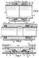
- the coupling incorporates an externally threaded sleeve 30 having internal grooves for the reception of O-rings 32.
- a collet form of the wedging members 10 Positioned at each ends of the sleeve 30 is a collet form of the wedging members 10, as described with reference with reference to Figures 1 and 2, the collet being arranged with its end surface 12 in abutting relationship with the opposite ends of the sleeve 30.
- cap nuts 34 Threaded onto the sleeve 30 are cap nuts 34, the respective cap nuts having tapered inner surfaces 36 of corresponding taper to the outer surface 18 of the collet.
- the cap nuts 34 are then threaded down on the sleeve 30 in order to force the tapered surface 36 of the respective cap nuts axially relative to the wedging members 10 of collet, and in so doing contract the collet in diameter, and in turn, force the grit particles 24 on the inner surface of the coupling respective wedging members into biting and gripping engagement with the pipe ends.
- FIG. 4 A similar configuration is illustrated in Figure 4, but in the reverse of the embodiment of Figure 3.
- the sleeve 40 is internally threaded, and is provided internally with grooves for the reception of sealing rings 42.
- Externally threaded ring nuts are threaded into the bores of the sleeve 40, the respective ring nuts having tapered internal surfaces 46 of corresponding taper to the taper of the external surface of the wedging members 10 of the collet.
- pipes 48 are "stabbed” into the coupling, subsequent to which the ring nuts 44 are tightened down in order to contract the collet, and, in the same manner as the embodiment of Figure 3, cause the grit particles on the inner surfaces of the wedging members to bite into and grip the pipes.
- Figures 3 and 4 are particularly advantageous for use with pipe formed from plastics material, the coupling itself (including the sleeve and the cap nuts or ring nuts) being formed from a moldable plastics material.
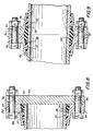
- an internally threaded sleeve 50 is provided with internal recesses for the reception of sealing rings 52, the wedging members 10 being received within the tapered inner surfaces 56 of ring nuts 54.
- the sleeve 50 and the ring nuts 54 each can be formed from a moldable plastics material.
- the internally threaded sleeve 50 is encased in a sleeve of a structurally strong metal 51, which conveniently can be a sleeve formed from the same metal as the pipes 58.
- Figure 6 An extremely useful modification of the concept of Figure 5 is illustrated in Figure 6, in which the right-hand end of the coupling is formed in exactly the same manner as the right-hand end of the coupling in Figure 5.
- the left-hand end of the coupling is a sliding fit over a pipe, and is sealed against the pipe such that the pipe can slide internally within the associated left-hand end coupling, thus providing a highly effective but relatively inexpensive expansion joint for pipes.
- the internally threaded sleeve is indicated at 60, the sealing rings at 62, and the single ring nut at 64.
- the ring nut 64 has an internal taper 66 corresponding with that of the external surface of the wedging members 10, the sleeve 60 being structurally reinforced by an external sleeve 61 in the event that the sleeve 60 is formed from a plastics material, the sleeve 61 being formed from a suitable metal.
- one end of the coupling becomes rigidly attached to the pipe 68, the other end of the coupling being arranged in sliding relationship with respect to the pipe 69, thus enabling the pipe 69 to move relative to the coupling and expand into the coupling or contract within the coupling, within the permitted linear extent of such expansion of contraction.
- FIG 7 A further embodiment of coupling embodying exactly the same principles as those discussed ith respect to Figures 3, 4 and 5 is illustrated in Figure 7, this coupling having particular application in securing and sealing pipes formed from plastic reinforced fiber glass, thin wall fiber glass pipes being inherently weak when placed under radial compression.
- a sleeve 70 formed, for example, from stainless steel or any other suitable metal, extends in bridging relationship with the pipe ends and spigots into end members 74 which are axially slidable relative to the pipes and also relative to the sleeve 70, the end members 74 each having an internally tapered surface 76 of corresponding taper to the external surface of the contained wedging members 10.
- Sealing rings 72 of an elastomeric material are positioned in abutting relationship with the end faces 12 of the respective wedging members, thus providing a reaction member against which the wedging members 10 react.
- traction bolts 78 Extending between the end members 74 are traction bolts 78.
- the end members 74 are moved axially towards each other in sliding relationship within the sleeve 70.
- the tapered surfaces 76 of the end members 74 contract the wedging members 10 into clamping engagement with the pipes 79, and, additionally act to move the wedging members 10 axially towards each other form them to compress the sealing rings 72, the sealing rings 72 in turn acting as the reaction members for the wedging members 10.
- the coupling if desired, can be removed from the associated pipes, either to permit adjustment of the piping assembly or re-use of the coupling at some other location.
- the couplings presently described may find equal applicability both in permanent and in temporary installations.
- an additional advantage of the embodiments of Figures 4 through 7 is that the coupling itself is capable of producing a force acting to increase the holding power of the coupling upon pressurization of the piping system. This is due to the seals employed having face engagement with the ends face 12 of the respective wedging members. Thus, upon a pressure rise in the piping system, a correspondingly increasing axial force is exerted on the seals by the pressurized fluid.
- This increase in axial force is transmitted directly to the wedging members in an opposite axial direction to the force produced by the camming surfaces, and in turn results in an additive axial force exerted on the wedging members and an increase in the force acting radially inwardly of the wedging members to further increase the holding power of those members, which acts not only to resist axial movement between the coupling and the pipes but also to resist relative rotation between those members.
- FIG. 8 and 9 A further embodiment of the coupling of the invention is shown in Figures 8 and 9, the coupling of Figure 9 being comprised of two of the couplings of Figure 8 joined to each other.
- the wedging members 10 are held within an end flange member 84 having a tapered inner surface 86.
- a back-up ring 88 of plastic or other material provides a reaction member at the larger diameter end of the wedging members, and also provides a reaction member for an annular seal 90.
- the end flange member 84 is provided with bolt holes 92 arranged in its radially extending flange, thus permitting the member 84 to be drawn axially towards a blind flange 94, or towards a juxtaposed end flange member 84 as shown in Figure 9 by torquing down traction bolts 96.
Claims (20)
- Accouplement pour tuyau en matériau ductile, destiné à s'adapter sur une extrémité de tuyau et à s'accrocher à celle-ci et comportant :
un manchon (30, 40, 50, 60, 70) contenant un élément d'étanchéité (32, 42, 52, 62, 72) assurant l'herméticité autour de la surface extérieure d'une extrémité de tuyau lorsqu'il est accroché par l'accouplement en service;
une bague de came (34, 44, 54, 64, 74, 84) montée de manière à se déplacer axialement par rapport au manchon et ayant une surface de came orientée radialement vers l'intérieur (36, 46, 56, 66, 76, 86) ayant une conicité intérieure dans la direction s'écartant de l'extrémité de tuyau en service, et
un élément de coin compressible périphériquement (10) comprenant des fractions de coin réalisées en un matériau ductile et disposées dans l'accouplement et présentant (i) une surface de came orientée radialement vers l'extérieur qui peut venir en contact avec la surface de came orientée vers l'intérieur de la bague de came et qui présente une conicité complémentaire par rapport à celle-ci, et (ii) une surface d'accrochage du tuyau orientée vers l'intérieur;
dans lequel le déplacement axial de la bague de came vers l'extrémité de tuyau et par rapport au manchon permet de comprimer les parties de coin vers l'intérieur, de manière à accrocher la surface extérieure du tuyau en service,
et dans lequel l'ensemble de la surface d'accrochage du tuyau de l'assemblage des coins supporte des particules dures (24) qui mordent dans la surface extérieure du tuyau en service, les particules dures étant plus dures que le matériau ductile des éléments de coin et du tuyau à accrocher, de manière à être encastrées dans le matériau ductile de la surface du tuyau et la surface d'accrochage du tuyau à son interface lorsque la surface d'accrochage du tuyau vient accrocher l'extérieur du tuyau en service. - Accouplement selon la revendication 1, dans lequel les particules dures (24) sont collées à la surface d'accrochage du tuyau qui est en matériau ductile.
- Accouplement selon la revendication 1, dans lequel les particules dures (24) sont pré-encastrées dans la surface accrochant le tuyau, qui est en matériau ductile.
- Accouplement selon la revendication 1, dans lequel la surface accrochant le tuyau a une feuille de recouvrement (23) et les particules dures (24) sont fixées à la feuille (23).
- Accouplement selon la revendication 4, dans lequel les particules dures (24) sont encastrées dans la feuille (23).
- Accouplement selon l'une quelconque des revendications précédentes, dans lequel les éléments de coin comprennent des pièces séparées en matériau ductile disposées circulairement, de manière à former l'assemblage de coins (10).
- Accouplement selon l'une quelconque des revendications 1 à 5, dans lequel les parties de coin sont interconnectées pour former un assemblage de collet (10).
- Accouplement selon la revendication 7, dans lequel chacun des éléments de coin orienté axialement est assemblé d'une pièce à l'élément voisin sur un côté de son extrémité axiale et à l'élément voisin de l'autre côté de son extrémité axiale, de manière à former un assemblage crénelé.
- Accouplement selon la revendication 7, dans lequel les éléments de coin sont des pièces séparées de matériau ductile, maintenues ensemble écartées les unes des autres dans le sens périphérique sur une feuille de support (23).
- Accouplement selon l'une quelconque des revendications précédentes, dans lequel les éléments de coin sont réalisés en matière plastique moulable.
- Accouplement selon l'une quelconque des revendications précédentes, dans lequel les éléments de coin sont réalisés en matériau fibreux imprégné par un agent de liaison.
- Accouplement selon l'une quelconque des revendications précédentes, dans lequel les éléments de coin sont moulés ou coulés.
- Accouplement selon l'une quelconque des revendications précédentes, dans lequel les particules dures (24) sont formées de carborundum, d'oxyde d'aluminium ou de carbure de silicium.
- Accouplement selon l'une quelconque des revendications précédentes, dans lequel la bague de came est un écrou à chapeau (34) qui est vissé sur un filet extérieur du manchon (30).
- Accouplement selon l'une quelconque des revendications 1 à 13, dans lequel la bague de came est un écrou annulaire (44, 54, 64) qui est vissé dans un filet intérieur du manchon (40, 50, 60) et a un trou conique constituant sa surface de came intérieure.
- Accouplement selon la revendication 15, dans lequel le manchon (50) a un prolongement axial contenant un deuxième élément d'étanchéité (62) écarté axialement du premier, de manière à réaliser un joint de dilatation pour deux tuyaux.
- Accouplement selon l'une quelconque des revendications 1 à 13, dans lequel une bride d'extrémité annulaire s'étend vers l'extérieur depuis la bague de came et peut être boulonnée axialement sur une bride opposée, de façon que la bague de came comprime l'assemblage des coins.
- Accouplement selon l'une quelconque des revendications précédentes, comportant ladite bague de came à chaque extrémité axiale du manchon, chaque bague de came ayant un assemblage de coins correspondant (10) dans lequel l'accouplement peut être utilisé pour assembler l'une à l'autre deux extrémités de tuyau.
- Accouplement selon l'une quelconque des revendications 1 à 17, qui comporte une butée d'extrémité pour un tuyau.
- Accouplement selon l'une quelconque des revendications 1 à 18, dans lequel le manchon a une butée s'étendant radialement vers l'intérieur et disposée centralement dans le sens axial, qui crée une surface de réaction pour l'assemblage de coin par l'intermédiaire de l'élément d'étanchéité.
Priority Applications (2)
| Application Number | Priority Date | Filing Date | Title |
|---|---|---|---|
| DE1989612593 DE68912593T2 (de) | 1989-10-26 | 1989-10-26 | Rohrkupplung. |
| AT89311050T ATE100544T1 (de) | 1989-10-26 | 1989-10-26 | Rohrkupplung. |
Applications Claiming Priority (1)
| Application Number | Priority Date | Filing Date | Title |
|---|---|---|---|
| US07/279,434 US4886304A (en) | 1987-02-18 | 1988-12-02 | Abrasive grip pipe coupling |
Publications (2)
| Publication Number | Publication Date |
|---|---|
| EP0424583A1 EP0424583A1 (fr) | 1991-05-02 |
| EP0424583B1 true EP0424583B1 (fr) | 1994-01-19 |
Family
ID=23068957
Family Applications (1)
| Application Number | Title | Priority Date | Filing Date |
|---|---|---|---|
| EP89311050A Expired - Lifetime EP0424583B1 (fr) | 1988-12-02 | 1989-10-26 | Raccord pour tuyau |
Country Status (4)
| Country | Link |
|---|---|
| US (1) | US4886304A (fr) |
| EP (1) | EP0424583B1 (fr) |
| CA (1) | CA2001061C (fr) |
| ES (1) | ES2050249T3 (fr) |
Families Citing this family (42)
| Publication number | Priority date | Publication date | Assignee | Title |
|---|---|---|---|---|
| US5553971A (en) * | 1988-12-20 | 1996-09-10 | Intelpro Corporation | Double-containment underground piping system |
| GB8906949D0 (en) * | 1989-03-28 | 1989-05-10 | Marston Palmer Ltd | Coupling |
| US5003146A (en) * | 1989-08-28 | 1991-03-26 | Alexander Rayburn G | Universal fitting for metal disintegration electrodes |
| CA2130191A1 (fr) * | 1992-02-19 | 1993-09-02 | Michael C. Webb | Systeme de tuyauterie a enfouir, sans danger pour l'environnement |
| KR0127286B1 (ko) * | 1992-02-28 | 1998-04-07 | 베른트 하베르자크 | 스트어링 칼럼 튜브의 베어링 마운트 |
| US5494374A (en) | 1992-03-27 | 1996-02-27 | Youngs; Andrew | Secondary containment flexible underground piping system |
| US5865216A (en) | 1995-11-08 | 1999-02-02 | Advanced Polymer Technology, Inc. | System for housing secondarily contained flexible piping |
| NL1009734C2 (nl) * | 1998-07-24 | 2000-01-25 | Fischer Georg Waga Nv | Koppelinrichting en werkwijze voor de vervaardiging van een in een dergelijke koppelinrichting te gebruiken gripring. |
| NL1002514C2 (nl) | 1996-03-04 | 1997-09-05 | Fischer Georg Waga Nv | Koppelinrichting. |
| DE19634352A1 (de) * | 1996-08-26 | 1998-03-05 | Kanis Paul Gerhard Dipl Ing | Rohrverbindungs-System |
| WO1998030825A1 (fr) * | 1997-01-13 | 1998-07-16 | Perfection Corporation | Raccord de type a tige dote d'une bague de serrage comportant des nervures de verrouillage |
| FR2762054B1 (fr) * | 1997-04-09 | 1999-05-21 | Pont A Mousson | Jonc fendu metallique pour joint verrouille entre elements de canalisation, et joint verrouille correspondant |
| JP3871428B2 (ja) * | 1998-02-16 | 2007-01-24 | シーケーディ株式会社 | 溶接レス継手 |
| IL136078A0 (en) * | 2000-05-11 | 2001-05-20 | Plasson Ltd | Pipe coupling and captive seal therefor |
| US6502865B1 (en) | 2000-08-09 | 2003-01-07 | Dynamic Air | Pipe coupler and method of coupling |
| US7125054B2 (en) * | 2003-05-19 | 2006-10-24 | S & B Technical Products, Inc. | Self restraining gasket and pipe joint |
| US6874696B1 (en) * | 2003-06-23 | 2005-04-05 | Orbit Irrigation Products, Inc. | Adjustable sprinkler riser with offset joint |
| US20050104375A1 (en) * | 2003-11-12 | 2005-05-19 | Thompson Steven L. | Coupling with pull-out resistance |
| US6932389B2 (en) * | 2003-12-31 | 2005-08-23 | Perfection Corporation | Connector with fluid line installation indicator |
| US7207606B2 (en) * | 2004-04-19 | 2007-04-24 | United States Pipe And Foundry Company, Llc | Mechanical pipe joint, gasket, and method for restraining pipe spigots in mechanical pipe joint bell sockets |
| GB2415472A (en) * | 2004-06-23 | 2005-12-28 | Gloway Internat Inc | A pipe coupling including hydraulically actuated pipe grippingmembers |
| US7762246B2 (en) * | 2004-08-10 | 2010-07-27 | Smart Parts, Inc. | Adjustable feed tube |
| NL1030404C2 (nl) * | 2005-11-11 | 2007-05-14 | Fischer Georg Waga Nv | Koppelinrichting voor een buis. |
| US7699354B2 (en) * | 2006-04-28 | 2010-04-20 | Beard Michael E | Marine riser assembly |
| DK200800240U4 (da) * | 2008-12-12 | 2010-03-26 | Hove As | Kompressionsfitting |
| US8448993B2 (en) | 2009-06-12 | 2013-05-28 | Romac Industries, Inc. | Pipe coupling |
| US11274777B2 (en) | 2009-06-12 | 2022-03-15 | Romac Industries, Inc. | Pipe coupling |
| US8312780B2 (en) | 2010-06-25 | 2012-11-20 | Mettler-Toledo Ag | Sampling device and method |
| US8365617B2 (en) | 2010-06-25 | 2013-02-05 | Mettler-Toledo Ag | Sampling device |
| US9010766B2 (en) * | 2011-04-11 | 2015-04-21 | DPR Futures LLC | Apparatus and methods for temporarily sealing a pipe |
| US9010812B2 (en) | 2012-03-07 | 2015-04-21 | Mettler-Toledo Autochem, Inc. | Reaction vessel probe adapter |
| US8894100B2 (en) | 2012-03-16 | 2014-11-25 | Romac Industries, Inc. | Fitting with draw mechanism |
| WO2015009305A1 (fr) * | 2013-07-18 | 2015-01-22 | Halliburton Energy Services, Inc. | Systèmes et procédés de raccord de tuyaux |
| WO2015130427A1 (fr) * | 2014-02-27 | 2015-09-03 | Sundew Technologies, Llc | Raccords à joint mécanique |
| CN106795987B (zh) * | 2014-09-02 | 2019-06-28 | 实用动力集团 | 管连接器 |
| CN106764150B (zh) * | 2017-03-27 | 2019-02-26 | 戴爱清 | 卡环锁紧式管道连接组件 |
| US11445893B2 (en) * | 2018-01-05 | 2022-09-20 | Boston Scientific Scimed, Inc. | Medical device connection member |
| US10464140B1 (en) | 2018-05-07 | 2019-11-05 | Techniks, LLC | Method and apparatus for retaining a tool in a tool holder |
| KR102362653B1 (ko) * | 2019-06-21 | 2022-02-14 | 샘찬에너지(주) | 튜브 피팅 조립 방법 |
| US11406093B2 (en) * | 2019-08-16 | 2022-08-09 | Gem Products, Inc. | Extensible pole coupling assembly |
| RU2734297C1 (ru) * | 2019-10-21 | 2020-10-14 | Алил Алиомарович Ахмедов | Соединение ремонтное трубопровода из полимерных труб |
| US20210186089A1 (en) * | 2019-12-20 | 2021-06-24 | Kristian R. Merwin | Collar |
Family Cites Families (17)
| Publication number | Priority date | Publication date | Assignee | Title |
|---|---|---|---|---|
| FR946749A (fr) * | 1944-04-05 | 1949-06-13 | Raccord pour tuyauterie | |
| US2479058A (en) * | 1944-09-25 | 1949-08-16 | Gustin Bacon Mfg Co | Flexible coupling |
| US2452275A (en) * | 1944-12-22 | 1948-10-26 | George V Woodling | Tube fitting coupling |
| US2531922A (en) * | 1945-02-08 | 1950-11-28 | Pidco Ltd | Pipe coupling and the like |
| US2459956A (en) * | 1945-05-16 | 1949-01-25 | John L Lenz | Pipe coupling |
| US2617672A (en) * | 1948-06-23 | 1952-11-11 | Harry J Nichols | Coupling |
| AT182275B (de) * | 1950-11-27 | 1955-06-10 | Engelbert Hawle | Rohrverbindung |
| US3149861A (en) * | 1958-10-01 | 1964-09-22 | Larsson Gunnar | Tube coupling |
| US3077638A (en) * | 1959-07-22 | 1963-02-19 | Westinghouse Electric Corp | Method for producing a sealing gasket |
| FR1323353A (fr) * | 1962-05-25 | 1963-04-05 | Pièce de raccordement, ou de connexion, pour tuyaux lisses, notamment pour tuyaux en matière synthétique | |
| US3252192A (en) * | 1964-04-01 | 1966-05-24 | Joseph B Smith | Clamp ring for pipe and the like |
| US3325195A (en) * | 1964-11-30 | 1967-06-13 | Edward R Margis | Coupling and sealing structures |
| US3428339A (en) * | 1966-02-07 | 1969-02-18 | Hays Mfg Co | Pipe coupling |
| DE2415699C3 (de) * | 1974-04-01 | 1981-12-24 | Seiler, Georg, 8000 München | Zug- und schubgesicherte Schraubmuffen-Verbindung von Rohren, insb. duktilen Gußrohren |
| ZA763467B (en) * | 1976-06-11 | 1978-02-22 | Aeci Ltd | Couplings |
| US4229025A (en) * | 1978-04-25 | 1980-10-21 | Perfection Corporation | Stab-type coupling |
| NZ209718A (en) * | 1984-09-28 | 1989-01-27 | J H Wier | Pipe connector |
-
1988
- 1988-12-02 US US07/279,434 patent/US4886304A/en not_active Expired - Lifetime
-
1989
- 1989-10-19 CA CA002001061A patent/CA2001061C/fr not_active Expired - Fee Related
- 1989-10-26 ES ES89311050T patent/ES2050249T3/es not_active Expired - Lifetime
- 1989-10-26 EP EP89311050A patent/EP0424583B1/fr not_active Expired - Lifetime
Also Published As
| Publication number | Publication date |
|---|---|
| EP0424583A1 (fr) | 1991-05-02 |
| US4886304A (en) | 1989-12-12 |
| ES2050249T3 (es) | 1994-05-16 |
| CA2001061C (fr) | 1993-04-27 |
| CA2001061A1 (fr) | 1990-06-02 |
Similar Documents
| Publication | Publication Date | Title |
|---|---|---|
| EP0424583B1 (fr) | Raccord pour tuyau | |
| US7207606B2 (en) | Mechanical pipe joint, gasket, and method for restraining pipe spigots in mechanical pipe joint bell sockets | |
| US5636878A (en) | Pipe coupling | |
| EP0204445B1 (fr) | Appareil de raccord en tubes de matières plastiques et méthode pour son utilisation | |
| EP0663555B1 (fr) | Ensemble de raccordement de tube | |
| US5306051A (en) | Self-aligning and self-tightening hose coupling and method therefor | |
| US4152821A (en) | Pipe joining connection process | |
| CA2513468C (fr) | Raccord pour tuyau composite | |
| US3794360A (en) | External swage end fitting | |
| US5829793A (en) | Self-restrained adapter system for connecting plastic pipe system to metallic pipe system | |
| AU553374B2 (en) | Unitary clamp action fitting | |
| US4854613A (en) | Composite connecting member for hydraulic fluid lines | |
| US3809412A (en) | Pipe couplings | |
| GB2257764A (en) | Clamping device for hose and pipe connector | |
| CA1136672A (fr) | Adaptateur de raccordement des tuyaux en plastique aux tuyaux en fonte | |
| US4252349A (en) | High pressure plastic pipe coupling | |
| GB2249599A (en) | End-fittings for pipes with compressible linings | |
| AU677803B2 (en) | Pipe coupling | |
| JP2534967Y2 (ja) | 鋼管接続用のメカニカル継手装置 | |
| JP2537578B2 (ja) | 管継手 | |
| GB2200180A (en) | Pipe coupling | |
| JPH017908Y2 (fr) | ||
| GB2080463A (en) | Improvements in apparatus for sealing pipe joints | |
| JP2000081175A (ja) | 管継手 | |
| CA1077084A (fr) | Raccord pour tuyaux |
Legal Events
| Date | Code | Title | Description |
|---|---|---|---|
| PUAI | Public reference made under article 153(3) epc to a published international application that has entered the european phase |
Free format text: ORIGINAL CODE: 0009012 |
|
| AK | Designated contracting states |
Kind code of ref document: A1 Designated state(s): AT BE CH DE ES FR GB IT LI LU NL SE |
|
| 17P | Request for examination filed |
Effective date: 19910521 |
|
| 17Q | First examination report despatched |
Effective date: 19920218 |
|
| GRAA | (expected) grant |
Free format text: ORIGINAL CODE: 0009210 |
|
| AK | Designated contracting states |
Kind code of ref document: B1 Designated state(s): AT BE CH DE ES FR GB IT LI LU NL SE |
|
| REF | Corresponds to: |
Ref document number: 100544 Country of ref document: AT Date of ref document: 19940215 Kind code of ref document: T |
|
| REF | Corresponds to: |
Ref document number: 68912593 Country of ref document: DE Date of ref document: 19940303 |
|
| ITF | It: translation for a ep patent filed |
Owner name: MODIANO & ASSOCIATI S.R.L. |
|
| ET | Fr: translation filed | ||
| REG | Reference to a national code |
Ref country code: ES Ref legal event code: FG2A Ref document number: 2050249 Country of ref document: ES Kind code of ref document: T3 |
|
| PLBE | No opposition filed within time limit |
Free format text: ORIGINAL CODE: 0009261 |
|
| STAA | Information on the status of an ep patent application or granted ep patent |
Free format text: STATUS: NO OPPOSITION FILED WITHIN TIME LIMIT |
|
| 26N | No opposition filed | ||
| EAL | Se: european patent in force in sweden |
Ref document number: 89311050.2 |
|
| PGFP | Annual fee paid to national office [announced via postgrant information from national office to epo] |
Ref country code: ES Payment date: 19991006 Year of fee payment: 11 |
|
| PGFP | Annual fee paid to national office [announced via postgrant information from national office to epo] |
Ref country code: GB Payment date: 19991015 Year of fee payment: 11 |
|
| PGFP | Annual fee paid to national office [announced via postgrant information from national office to epo] |
Ref country code: FR Payment date: 19991018 Year of fee payment: 11 |
|
| PGFP | Annual fee paid to national office [announced via postgrant information from national office to epo] |
Ref country code: SE Payment date: 19991020 Year of fee payment: 11 Ref country code: DE Payment date: 19991020 Year of fee payment: 11 Ref country code: CH Payment date: 19991020 Year of fee payment: 11 |
|
| PGFP | Annual fee paid to national office [announced via postgrant information from national office to epo] |
Ref country code: NL Payment date: 19991021 Year of fee payment: 11 |
|
| PGFP | Annual fee paid to national office [announced via postgrant information from national office to epo] |
Ref country code: LU Payment date: 19991022 Year of fee payment: 11 Ref country code: AT Payment date: 19991022 Year of fee payment: 11 |
|
| PGFP | Annual fee paid to national office [announced via postgrant information from national office to epo] |
Ref country code: BE Payment date: 19991027 Year of fee payment: 11 |
|
| PG25 | Lapsed in a contracting state [announced via postgrant information from national office to epo] |
Ref country code: LU Free format text: LAPSE BECAUSE OF NON-PAYMENT OF DUE FEES Effective date: 20001026 Ref country code: GB Free format text: LAPSE BECAUSE OF NON-PAYMENT OF DUE FEES Effective date: 20001026 Ref country code: AT Free format text: LAPSE BECAUSE OF NON-PAYMENT OF DUE FEES Effective date: 20001026 |
|
| PG25 | Lapsed in a contracting state [announced via postgrant information from national office to epo] |
Ref country code: ES Free format text: LAPSE BECAUSE OF NON-PAYMENT OF DUE FEES Effective date: 20001027 |
|
| PG25 | Lapsed in a contracting state [announced via postgrant information from national office to epo] |
Ref country code: SE Free format text: THE PATENT HAS BEEN ANNULLED BY A DECISION OF A NATIONAL AUTHORITY Effective date: 20001030 |
|
| PG25 | Lapsed in a contracting state [announced via postgrant information from national office to epo] |
Ref country code: LI Free format text: LAPSE BECAUSE OF NON-PAYMENT OF DUE FEES Effective date: 20001031 Ref country code: CH Free format text: LAPSE BECAUSE OF NON-PAYMENT OF DUE FEES Effective date: 20001031 Ref country code: BE Free format text: LAPSE BECAUSE OF NON-PAYMENT OF DUE FEES Effective date: 20001031 |
|
| BERE | Be: lapsed |
Owner name: VICTAULIC CY OF AMERICA Effective date: 20001031 |
|
| PG25 | Lapsed in a contracting state [announced via postgrant information from national office to epo] |
Ref country code: NL Free format text: LAPSE BECAUSE OF NON-PAYMENT OF DUE FEES Effective date: 20010501 |
|
| GBPC | Gb: european patent ceased through non-payment of renewal fee |
Effective date: 20001026 |
|
| REG | Reference to a national code |
Ref country code: CH Ref legal event code: PL |
|
| EUG | Se: european patent has lapsed |
Ref document number: 89311050.2 |
|
| PG25 | Lapsed in a contracting state [announced via postgrant information from national office to epo] |
Ref country code: FR Free format text: LAPSE BECAUSE OF NON-PAYMENT OF DUE FEES Effective date: 20010629 |
|
| NLV4 | Nl: lapsed or anulled due to non-payment of the annual fee |
Effective date: 20010501 |
|
| PG25 | Lapsed in a contracting state [announced via postgrant information from national office to epo] |
Ref country code: DE Free format text: LAPSE BECAUSE OF NON-PAYMENT OF DUE FEES Effective date: 20010703 |
|
| REG | Reference to a national code |
Ref country code: FR Ref legal event code: ST |
|
| REG | Reference to a national code |
Ref country code: ES Ref legal event code: FD2A Effective date: 20011113 |
|
| PG25 | Lapsed in a contracting state [announced via postgrant information from national office to epo] |
Ref country code: IT Free format text: LAPSE BECAUSE OF NON-PAYMENT OF DUE FEES;WARNING: LAPSES OF ITALIAN PATENTS WITH EFFECTIVE DATE BEFORE 2007 MAY HAVE OCCURRED AT ANY TIME BEFORE 2007. THE CORRECT EFFECTIVE DATE MAY BE DIFFERENT FROM THE ONE RECORDED. Effective date: 20051026 |