EP0424276B1 - Improvement in extendable flexible walls - Google Patents
Improvement in extendable flexible walls Download PDFInfo
- Publication number
- EP0424276B1 EP0424276B1 EP19900402958 EP90402958A EP0424276B1 EP 0424276 B1 EP0424276 B1 EP 0424276B1 EP 19900402958 EP19900402958 EP 19900402958 EP 90402958 A EP90402958 A EP 90402958A EP 0424276 B1 EP0424276 B1 EP 0424276B1
- Authority
- EP
- European Patent Office
- Prior art keywords
- cloth
- flexible wall
- wall according
- elastic devices
- lower section
- Prior art date
- Legal status (The legal status is an assumption and is not a legal conclusion. Google has not performed a legal analysis and makes no representation as to the accuracy of the status listed.)
- Expired - Lifetime
Links
Images

Classifications
-
- B—PERFORMING OPERATIONS; TRANSPORTING
- B60—VEHICLES IN GENERAL
- B60J—WINDOWS, WINDSCREENS, NON-FIXED ROOFS, DOORS, OR SIMILAR DEVICES FOR VEHICLES; REMOVABLE EXTERNAL PROTECTIVE COVERINGS SPECIALLY ADAPTED FOR VEHICLES
- B60J5/00—Doors
- B60J5/04—Doors arranged at the vehicle sides
- B60J5/06—Doors arranged at the vehicle sides slidable; foldable
- B60J5/062—Doors arranged at the vehicle sides slidable; foldable for utility vehicles or public transport
- B60J5/065—Doors arranged at the vehicle sides slidable; foldable for utility vehicles or public transport with non-rigid elements, e.g. side curtains
Definitions
- the present invention relates to an improvement to the flexible extensible walls and more particularly to the side walls which are encountered in particular on transport vehicles of the type comprising a lifting roof which makes it possible to adapt the volume of the vehicle to the load transported.
- Walls of this type are described in particular in document GB-A-797,458.
- This document presents an expandable cover used to protect the loads placed on vehicles such as truck platforms; the volume of said loadings can vary between a maximum limit and a predetermined minimum limit.
- This extendable cover has a vertical panel of determined dimensions and a retractable extension, developable at will.
- This tarpaulin is maintained from its upper part by means of elastic mooring members which slide in sleeves. When the extension is folded inside, on the main panel, it is stapled to this main panel by means of male and female pressure devices.
- Such a tarpaulin is adjustable in different positions to adapt to the load.
- the subject of the present invention is a tarpaulin also forming an extensible wall, which however offers the possibility of adapting to all possible lengths between a maximum and a minimum.
- the invention also makes it possible to obtain a perfectly flat wall without creases or pucks of unpleasant appearance.
- the flexible wall according to the invention is in the form of a sliding curtain closing one side of a transport vehicle of the type described in document FR-A-2 577 865.
- This wall comprises elastic members arranged in the direction of the tarpaulin extension; these elastic members are fixed on the canvas of the sheet, at least at two points which are spaced, on said canvas, of a length at least equal to the difference between the maximum dimension and the minimum dimension of the wall the capacity of elongation of said elastic members is also at least equal to this difference.
- This arrangement allows the automatic formation of a fold at the bottom of the sheet, between the two fixing points of the elastic members, which fold absorbs the variations in size of the wall.
- the wall comprises elastic members in the form of straps, which extend from the upper part of the fabric of said wall, to its lower part, which lower part comprises means of hooking cooperating with the edge of the vehicle floor.
- the wall comprises elastic members which extend into gussets arranged from the upper part of the wall, over a length substantially less than the minimum dimension of said wall.
- the lower edge of the wall comprises, in the extension of the elastic members, a handle facilitating the tension and the attachment of said lower part to the side of the vehicle.
- the wall consists of a flexible fabric 1 suspended by means of roller carriages 2 in a rail 3 disposed at the edge of the roof 4 of the vehicle.
- straps 5 which extend vertically inside and / or outside the fabric 1, starting from the carriages 2, to reinforce it.
- the carriages 2 are generally spaced about 50 cm apart.
- elastic members 6 in the form of straps or bungee cords, fixed by any suitable means to their upper part 7 at the upper edge 8 of the fabric 1 and to their lower part 9 , near the lower edge 10 of said fabric 1. It is noted, in the extension of each elastic member 6, at the lower part of the fabric 1, a hook-shaped hooking device 11 fixed by means of a strap 12 near the bottom edge 10 of the wall. This hook 11 is intended to grip under the bank 13 of the floor 14 of the vehicle.
- the strap 12 is a non-extensible strap fixed on the lower longitudinal strip 15 of the fabric 1.
- the elastic member 6 is preferably positioned in a protective sheath 16, inside which it is free to slide vertically.
- the height of this sheath 16 is substantially less than the dimension wall minimum.
- the elongation capacity of the elastic members 6 is at least equal to the difference in height of the roof in the lowered and raised position.
- the elastic member 6 exerts traction between its anchor point 7 located at the upper edge 8 of the fabric and its anchor 9 located at the lower part of said fabric.
- the lower anchoring of the elastic member 6 is maintained in a constant fixed position, by means of the hook 11 fixed to the edge 13.
- the lower longitudinal strip 15 of the fabric 1 which extends from the edge 10 to the level anchors 9 of the elastic member 6, remains in a fixed position relative to the bank 13, which position results from that of the hooks 11 fixed to their strap 12.
- a handle 22 is disposed on the strap 12, above the hook 11, to allow the operator to more easily exert a tension on the strap 6 for the positioning of said hook 11 under the edge 13.
- the vertical tension on the fabric 1 is achieved by means of straps 18 at the ends of which there is a hook 19 which also cooperates with the bank 13.
- a loop 20 makes it possible to adjust the length and the tension of the straps 18, which, generally, are fixed to the lower end of the straps 5, outside the fabric 1. This gives a flexible wall that is perfectly flat and above all without unsightly fold at the bottom. Fold 17 is carried out automatically under the level 21 of the longitudinal strip 15, simply because of the weight of the fabric. This level 21 appears on the internal face of the wall, FIGS. 3 to 6.
- the elastic members 6 are distributed approximately every meter along the length of the wall. They can be arranged vertically under the roller carriages 2, that is to say as a doubling of the straps 5, to avoid the formation of folds on the fabric 1.
- These straps 6 constitute a device which makes it possible to adjust the dimensions of the fabric in order to adapt it to the different positions of the roof 4 of the vehicle.
- the wall has a double hooking: a hooking by means of the conventional adjustable straps 18, which realize the vertical tension of the fabric 1 using the straps 5, and a flexible hooking by the elastic members 6 which hold the canvas 1 thanks to the protective sleeves 16.
- the tension of the strap 18 is exerted on the fabric 1 above the fold 17; this strap 18 is fixed to the outside of the fabric at the lower end of the sheath 16.
Description
La présente invention concerne un perfectionnement aux parois souples extensibles et plus particulièrement aux parois latérales que l' on rencontre notamment sur des véhicules de transport du type comportant un toit relevable qui permet d'adapter le volume du véhicule à la charge transportée.The present invention relates to an improvement to the flexible extensible walls and more particularly to the side walls which are encountered in particular on transport vehicles of the type comprising a lifting roof which makes it possible to adapt the volume of the vehicle to the load transported.
Des parois de ce type sont notamment décrites dans le document GB-A-797 458. Ce document présente une bâche extensible servant à protéger les chargements disposés sur des véhicules comme des plateformes de camions ; le volume desdits chargements pouvant varier entre une limite maximale et une limite minimale prédéterminée. Cette bâche extensible comporte un panneau vertical de dimensions déterminées et une rallonge escamotable, développable à volonté. Cette bâche est maintenue, depuis sa partie supérieure au moyen d'organes élastiques d'amarrage qui coulissent dans des manches. Lorsque la rallonge est repliée à l'intérieur, sur le panneau principal, elle est agrafée à ce panneau principal au moyen de dispositifs à pressions mâle et femelle.Walls of this type are described in particular in document GB-A-797,458. This document presents an expandable cover used to protect the loads placed on vehicles such as truck platforms; the volume of said loadings can vary between a maximum limit and a predetermined minimum limit. This extendable cover has a vertical panel of determined dimensions and a retractable extension, developable at will. This tarpaulin is maintained from its upper part by means of elastic mooring members which slide in sleeves. When the extension is folded inside, on the main panel, it is stapled to this main panel by means of male and female pressure devices.
Une telle bâche est réglable en différentes positions pour s'adapter au chargement.Such a tarpaulin is adjustable in different positions to adapt to the load.
L'opération qui consiste à replier et à agrafer la rallonge escamotable est difficile à réaliser surtout lorsqu'il y a peu d'espace entre le chargement et le panneau principal.The operation which consists in folding up and stapling the retractable extension is difficult to perform especially when there is little space between the load and the main panel.
La présente invention a pour objet une bâche formant une paroi extensible également, qui offre cependant la possibilité de s'adapter à toutes les longueurs possibles entre un maximum et un minimum.The subject of the present invention is a tarpaulin also forming an extensible wall, which however offers the possibility of adapting to all possible lengths between a maximum and a minimum.
L'invention permet également d'obtenir une paroi parfaitement plane sans pliure ou fronce d'aspect désagréable.The invention also makes it possible to obtain a perfectly flat wall without creases or pucks of unpleasant appearance.
La paroi souple selon l'invention se présente sous la forme d'un rideau coulissant obturant un côté d'un véhicule de transport du type de celui décrit dans le document FR-A-2 577 865. Cette paroi comporte des organes élastiques disposés dans le sens de l'allongement de la bâche ; ces organes élastiques sont fixés sur la toile de la bâche, au moins en deux points qui sont espacés, sur ladite toile, d'une longueur au moins égale à la différence entre la dimension maximale et la dimension minimale de la paroi la capacité d'allongement desdits organes élastiques est elle aussi au moins égale à cette différence. Cette disposition permet la formation automatique d'un pli à la partie inférieure de la bâche, entre les deux points de fixation des organes élastiques, lequel pli absorbe les variations de dimension de la paroi.The flexible wall according to the invention is in the form of a sliding curtain closing one side of a transport vehicle of the type described in document FR-A-2 577 865. This wall comprises elastic members arranged in the direction of the tarpaulin extension; these elastic members are fixed on the canvas of the sheet, at least at two points which are spaced, on said canvas, of a length at least equal to the difference between the maximum dimension and the minimum dimension of the wall the capacity of elongation of said elastic members is also at least equal to this difference. This arrangement allows the automatic formation of a fold at the bottom of the sheet, between the two fixing points of the elastic members, which fold absorbs the variations in size of the wall.
Selon une disposition préférentielle de l'invention, la paroi comporte des organes élastiques en forme de sangles, qui s'étendent à la partie supérieure de la toile de ladite paroi, jusqu'à sa partie inférieure, laquelle partie inférieure comporte des moyens d'accrochage coopérant avec la rive du plancher du véhicule.According to a preferred arrangement of the invention, the wall comprises elastic members in the form of straps, which extend from the upper part of the fabric of said wall, to its lower part, which lower part comprises means of hooking cooperating with the edge of the vehicle floor.
Selon une autre disposition de l'invention, la paroi comporte des organes élastiques qui s'étendent dans des goussets aménagés à partir de la partie supérieure de la paroi, sur une longueur sensiblement inférieure à la dimension minimale de ladite paroi.According to another arrangement of the invention, the wall comprises elastic members which extend into gussets arranged from the upper part of the wall, over a length substantially less than the minimum dimension of said wall.
Toujours selon l'invention, la bordure inférieure de la paroi, comporte, dans le prolongement des organes élastiques, une poignée facilitant la tension et l'accrochage de ladite partie inférieure sur la rive du véhicule.Still according to the invention, the lower edge of the wall comprises, in the extension of the elastic members, a handle facilitating the tension and the attachment of said lower part to the side of the vehicle.
L'invention sera encore illustrée à l'aide de la description suivante et des dessins annexés donnés à titre indicatif, et dans lesquels :
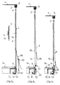
- la figure 1 illustre une portion de paroi souple, vue de l'intérieur du véhicule, laquelle paroi est dans une position de dimensions maxima, c'est-à-dire totalement développée ;
- la figure 2 est une vue en coupe selon A de la figure 1, montrant la paroi souple en position sur un véhicule partiellement esquissé, avec une section agrandie montrant un fourreau ;
- la figure 3 illustre une portion de la paroi souple, toujours vue de l'intérieur, montrant sa dimension minimale ;
- la figure 4 est une coupe selon A de la figure 3 ;
- la figure 5 illustre une portion de la paroi souple dans une position intermédiaire entre ses dimensions maximale et minimale ;
- la figure 6 est une vue en coupe selon A de la figure 5.
- FIG. 1 illustrates a portion of flexible wall, seen from inside the vehicle, which wall is in a position of maximum dimensions, that is to say fully developed;
- Figure 2 is a sectional view along A of Figure 1, showing the flexible wall in position on a partially sketched vehicle, with an enlarged section showing a sheath;
- FIG. 3 illustrates a portion of the flexible wall, still seen from the inside, showing its minimum dimension;
- Figure 4 is a section along A of Figure 3;
- FIG. 5 illustrates a portion of the flexible wall in an intermediate position between its maximum and minimum dimensions;
- FIG. 6 is a sectional view along A of FIG. 5.
Telle que représentée sur les figures, la paroi est constituée d'une toile souple 1 suspendue au moyen de chariots à galets 2 dans un rail 3 disposé en bordure du toit 4 du véhicule. On remarque, sur les figures, des sangles 5 qui s'étendent verticalement à l'intérieur et/ou a l'extérieur de la toile 1, partant des chariots 2, pour la renforcer.As shown in the figures, the wall consists of a
Les chariots 2 sont généralement espacés de 50 cm environ.The
On remarque, sur la face interne de la toile 1, des organes élastiques 6 en forme de sangles ou de sandows, fixés par tous moyens appropriés à leur partie supérieure 7 au niveau du rebord supérieur 8 de la toile 1 et à leur partie inférieure 9, à proximité du rebord inférieur 10 de ladite toile 1. On remarque, dans le prolongement de chaque organe élastique 6, à la partie inférieure de la toile 1, un dispositif d'accrochage en forme de crochet 11 fixé au moyen d'une sangle 12 près de la bordure inférieure 10 de la paroi. Ce crochet 11 est prévu pour s'agripper sous la rive 13 du plancher 14 du véhicule. La sangle 12 est une sangle non extensible fixée sur la bande longitudinale inférieure 15 de la toile 1.Note, on the internal face of the
L'organe élastique 6 est positionné, de préférence, dans un fourreau 16 de protection, à l'intérieur duquel il est libre en coulissement vertical. La hauteur de ce fourreau 16 est sensiblement inférieure à la dimension minimale de la paroi.The
La capacité d'allongement des organes élastiques 6 est au moins égale à la différence de hauteur du toit en position abaissée et relevée.The elongation capacity of the
Cette dimension minima de la paroi est représentée figure 3. En effet, sur cette figure, et sur la figure 4 notamment, on remarque que la partie inférieure de la toile 1 forme un pli 17 qui s'étend longitudinalement et qui est apparent sur la face interne de la paroi. La face externe de la paroi est parfaitement lisse comme on peut le remarquer figure 4.This minimum dimension of the wall is shown in Figure 3. Indeed, in this figure, and in Figure 4 in particular, we note that the lower part of the
L'organe élastique 6 exerce une traction entre son point d'ancrage 7 situé à la bordure supérieure 8 de la toile et son ancrage 9 situé à la partie inférieure de ladite toile. L'ancrage inférieur de l'organe élastique 6 est maintenu dans une position fixe constante, au moyen du crochet 11 fixé à la rive 13. La bande longitudinale inférieure 15 de la toile 1 qui s'étend de la bordure 10 jusqu'au niveau des ancrages 9 de l'organe élastique 6, reste dans une position fixe par rapport à la rive 13, laquelle position résulte de celle des crochets 11 fixés à leur sangle 12. Une poignée 22 est disposée sur la sangle 12, au-dessus du crochet 11, pour permettre à l' opérateur d'exercer plus facilement une tension sur la sangle 6 pour la mise en place dudit crochet 11 sous la rive 13.The
Lorsque la partie supérieure 8 de la paroi s'élève, le pli 17, figure 4, se réduit, comme il apparait figure 6 et disparait totalement figure 2, lorsque le toit 4 a atteint sa position relevée maximale.When the upper part 8 of the wall rises, the
La tension verticale sur la toile 1 est réalisée au moyen de sangles 18 aux extrémités desquelles on trouve un crochet 19 qui coopère avec la rive 13 également. Une boucle 20 permet de régler la longueur et la tension des sangles 18, qui, généralement, sont fixées à l'extrémité inférieure des sangles 5, à l'extérieur de la toile 1. On obtient ainsi une paroi souple parfaitement plane et surtout sans pliure inesthétique à la partie inférieure. Le pli 17 se réalise automatiquement sous le niveau 21 de la bande longitudinale 15, du simple fait du poids de la toile. Ce niveau 21 apparaît sur la face interne de la paroi, figures 3 à 6.The vertical tension on the
Les organes élastiques 6 sont répartis tous les mètres environ sur la longueur de la paroi. Ils peuvent être disposés verticalement sous les chariots à galets 2, c'est-à-dire en doublage des sangles 5, pour éviter la formation de plis sur la toile 1.The
Ces sangles 6 constituent un dispositif qui permet de régler les dimensions de la toile afin de l'adapter aux différentes positions du toit 4 du véhicule.These
Il faut également noter que la paroi comporte un double accrochage : un accrochage au moyen des sangles classiques réglables 18, qui réalisent la tension verticale de la toile 1 à l'aide des sangles 5, et un accrochage souple par les organes élastiques 6 qui maintiennent la toile 1 grâce aux fourreaux de protection 16.It should also be noted that the wall has a double hooking: a hooking by means of the conventional
La tension de la sangle 18, s'exerce sur la toile 1 au-dessus du pli 17 ; cette sangle 18 est fixée à l'extérieur de la toile au niveau de l'extrémité inférieure du fourreau 16.The tension of the
Les signes de référence insérés après les caractéristiques techniques mentionnées dans les revendications ont pour seul but de faciliter la compréhension de ces dernières et n'en limitent aucunement la portée.The reference signs inserted after the technical characteristics mentioned in the claims are intended only to facilitate the understanding of the latter and in no way limit their scope.
Claims (9)
- Flexible wall in the shape of a cloth stretched between the roof and the floor of a vehicle or equivalent with a raisable roof, the said wall being extendible by stretching the cloth between a maximum dimension and a minimum dimension in order to suit the various positions of the said roof with respect to the floor, characterised in that it comprises elastic devices (6) stretching in the extension direction of the said cloth (1) and which possess an elongation capacity at least equal to the difference between the maximum and minimum sizes of the wall, whereby the said elastic devices (6) are fixed on the said cloth in two points at least which are separated by a distance at least equal to the said difference.
- Flexible wall according to claim 1, characterised in that it comprises elastic devices (6) in the form of straps, which run from the upper section (8) of the cloth (1) to its lower section (10), the said lower section comprising fastening means (11) working together with the edge (13) of the floor (14) of the vehicle.
- Flexible wall according to any one of claims 1 or 2, characterised in that it contains elastic devices (6) guided in scabbards (16) running from the upper section (8) of the cloth (1) over a length equal to or less than the minimum size of the said cloth (1).
- Flexible wall according to any one of claims 1 to 3, characterised in that it contains, in the lower section of the cloth (1), in the prolongation of the elastic devices (6) handles (22) enabling to exert a pulling action on the said lower section of the cloth.
- Flexible wall according to claim 2, characterised in that it contains fastening means of the lower section of the cloth (1) made of a strap (12) at the end of which a hook (11) has been provided.
- Flexible wall according to claim 5, characterised in that it contains elastic devices (6) running from an anchoring point (7) located close to the upper rim (8) of the cloth, to an anchor (9) located close to the lower rim of the said cloth (1).
- Flexible wall according to any one of claims 2 to 6, characterised in that it contains elastic devices (6) anchored to the upper section of the cloth (1) close to the guiding saddles (2) of this cloth (1).
- Flexible wall according to claim 5, characterised in that it contains fastening means made of a strap (12) which is not extendible.
- Flexible wall according to any one of claims 3 to 8, characterised in that it contains straps (18) for vertical tightening, anchored to the lower section of the scabbards (16) for guiding the elastic devices (6).
Applications Claiming Priority (2)
| Application Number | Priority Date | Filing Date | Title |
|---|---|---|---|
| FR8913949A FR2653395B1 (en) | 1989-10-19 | 1989-10-19 | IMPROVEMENT IN FLEXIBLE EXTENSIBLE WALLS. |
| FR8913949 | 1989-10-19 |
Publications (2)
| Publication Number | Publication Date |
|---|---|
| EP0424276A1 EP0424276A1 (en) | 1991-04-24 |
| EP0424276B1 true EP0424276B1 (en) | 1995-04-12 |
Family
ID=9386739
Family Applications (1)
| Application Number | Title | Priority Date | Filing Date |
|---|---|---|---|
| EP19900402958 Expired - Lifetime EP0424276B1 (en) | 1989-10-19 | 1990-10-19 | Improvement in extendable flexible walls |
Country Status (4)
| Country | Link |
|---|---|
| EP (1) | EP0424276B1 (en) |
| DE (1) | DE69018566T2 (en) |
| ES (1) | ES2071060T3 (en) |
| FR (1) | FR2653395B1 (en) |
Families Citing this family (9)
| Publication number | Priority date | Publication date | Assignee | Title |
|---|---|---|---|---|
| FR2688463A1 (en) * | 1992-03-13 | 1993-09-17 | Bretagne Baches | Device for forming a horizontal fold for flexible walls of vertically-extendable bodywork |
| FR2688462A1 (en) * | 1992-03-16 | 1993-09-17 | Bretagne Baches | Improvement to the flexible walls of vertically-extendable bodywork |
| FR2706410B1 (en) * | 1993-06-16 | 1995-09-01 | Blond Baudouin | Improvement to the bodywork of vans with flexible walls. |
| FR2743772B1 (en) * | 1996-01-19 | 1998-04-10 | Bretagne Baches | IMPROVEMENT IN FLEXIBLE WALLS FOR VEHICLE BODIES IN PARTICULAR |
| DE19623452C2 (en) * | 1996-06-12 | 1998-05-14 | Halo Ges Fuer Innovative Nutzf | Fastening system for tarpaulins |
| EP0858930B1 (en) * | 1997-02-15 | 2001-12-12 | Schmitz-Anhänger Fahrzeugbau-Gesellschaft mbH & Co. | Tarpaulins with clamping device for lorries |
| NL1018006C2 (en) * | 2001-05-07 | 2002-11-08 | Christianus Franciscu Habraken | Container with height adjustable roof for transport by road or rail, has elastic device for keeping container side wall covers taught |
| ES2364363B1 (en) * | 2009-01-13 | 2012-09-14 | Adaico, S.L | CANVAS FOR CLOSURE OF TRUCK BOXES OR TRAILERS. |
| WO2016053218A1 (en) * | 2014-09-29 | 2016-04-07 | Tirsan Treyler Sanayi̇ Ve Ti̇caret Anoni̇m Şi̇rketi̇ | Duty-free bellow type tarp scretching system |
Family Cites Families (4)
| Publication number | Priority date | Publication date | Assignee | Title |
|---|---|---|---|---|
| BE545551A (en) * | 1956-03-07 | |||
| GB2041304A (en) * | 1979-02-24 | 1980-09-10 | Elsegood M | A Cover for Motor Vehicle Roof- Racks |
| DE3049566A1 (en) * | 1980-12-31 | 1982-07-29 | Heinz-Hubert Ing.(grad.) 4410 Warendorf Wolff | Elastic tarpaulin of double-cloth construction - incorporates elastic yarns to form extensible sidewall for lorry coverings, etc. |
| GB2093099B (en) * | 1981-02-12 | 1984-08-01 | Southfields Coachworks Ltd | Side curtain assembly for goods vehicles |
-
1989
- 1989-10-19 FR FR8913949A patent/FR2653395B1/en not_active Expired - Fee Related
-
1990
- 1990-10-19 EP EP19900402958 patent/EP0424276B1/en not_active Expired - Lifetime
- 1990-10-19 ES ES90402958T patent/ES2071060T3/en not_active Expired - Lifetime
- 1990-10-19 DE DE1990618566 patent/DE69018566T2/en not_active Expired - Fee Related
Also Published As
| Publication number | Publication date |
|---|---|
| FR2653395B1 (en) | 1995-01-06 |
| DE69018566D1 (en) | 1995-05-18 |
| EP0424276A1 (en) | 1991-04-24 |
| ES2071060T3 (en) | 1995-06-16 |
| DE69018566T2 (en) | 1995-12-21 |
| FR2653395A1 (en) | 1991-04-26 |
Similar Documents
| Publication | Publication Date | Title |
|---|---|---|
| FR2580007A3 (en) | ||
| EP0424276B1 (en) | Improvement in extendable flexible walls | |
| EP0041016B1 (en) | Automatically retractable stowing shelf | |
| WO2019224483A1 (en) | Covering device for a swimming pool | |
| FR2789107A1 (en) | FOLDABLE SHELTER WITH ELASTICALLY DEFORMABLE CARRIER STRUCTURE | |
| EP1359283B1 (en) | Protective cover for the guides of an industrial door | |
| FR2905969A1 (en) | Swimming pool covering equipment for use in e.g. garden, has reinforcing straps extending from transversal edge of water receiving basin, and stock cover with canvas spread on rectangular surface edging four sides of basin | |
| EP4162127A1 (en) | Tent comprising a bed base | |
| EP0787871B1 (en) | Awning or tent accessory and awning or tent comprising this accessory | |
| EP0221222A1 (en) | Device for the transverse partitioning of a motor vehicle | |
| FR2678868A1 (en) | Device for sealing the rear upper part of bodyworks with a raisable roof, fitted sealing curtain, and bodywork equipped with such a curtain | |
| FR2688463A1 (en) | Device for forming a horizontal fold for flexible walls of vertically-extendable bodywork | |
| FR2815309A1 (en) | Removable and transportable device, for fitting on hoppers or containers, is designed to roll and unroll protective covers, is fitted with rotation guides and with means for handling. | |
| FR2688462A1 (en) | Improvement to the flexible walls of vertically-extendable bodywork | |
| WO2011050939A1 (en) | Device for automatically unwinding and winding up a tarpaulin | |
| WO2009101515A1 (en) | Inflatable structure using a tie rod | |
| FR2545871A1 (en) | ARTICULATED PANEL WITH VERTICAL OPENING | |
| EP1405804A1 (en) | Covering element for container or the like | |
| EP0779401B1 (en) | Covering device for part of a pool, i.e. a swimming pool, such as stair or similar | |
| JP3335464B2 (en) | Sheet package for tent at building site, tubular cover, and tent construction method | |
| FR2898350A1 (en) | "CONTAINER BINTING DEVICE" | |
| WO2021181014A1 (en) | Compact device for covering a swimming pool | |
| FR2803317A1 (en) | Side wall for extending awning is fitted with a tubular strut inside the upper edge and is fastened to the side of the awning by clips and non slip grips | |
| FR2804198A1 (en) | Trolley for carrying kitbag has telescopic handles and plate at bottom which can be moved from position where it is loose and folded back to position where it is fixed and maintained in position by extended telescopic handles | |
| FR2964140B1 (en) | AWNING COMPRISING A WHEEL THAT CAN BE WRAPPED AND CORRESPONDING WHEEL |
Legal Events
| Date | Code | Title | Description |
|---|---|---|---|
| PUAI | Public reference made under article 153(3) epc to a published international application that has entered the european phase |
Free format text: ORIGINAL CODE: 0009012 |
|
| AK | Designated contracting states |
Kind code of ref document: A1 Designated state(s): BE DE ES FR GB LU NL |
|
| 17P | Request for examination filed |
Effective date: 19911017 |
|
| 17Q | First examination report despatched |
Effective date: 19930310 |
|
| GRAA | (expected) grant |
Free format text: ORIGINAL CODE: 0009210 |
|
| AK | Designated contracting states |
Kind code of ref document: B1 Designated state(s): BE DE ES FR GB LU NL |
|
| REF | Corresponds to: |
Ref document number: 69018566 Country of ref document: DE Date of ref document: 19950518 |
|
| REG | Reference to a national code |
Ref country code: ES Ref legal event code: FG2A Ref document number: 2071060 Country of ref document: ES Kind code of ref document: T3 |
|
| GBT | Gb: translation of ep patent filed (gb section 77(6)(a)/1977) |
Effective date: 19950530 |
|
| PLBE | No opposition filed within time limit |
Free format text: ORIGINAL CODE: 0009261 |
|
| STAA | Information on the status of an ep patent application or granted ep patent |
Free format text: STATUS: NO OPPOSITION FILED WITHIN TIME LIMIT |
|
| 26N | No opposition filed | ||
| REG | Reference to a national code |
Ref country code: FR Ref legal event code: GC |
|
| REG | Reference to a national code |
Ref country code: FR Ref legal event code: TP |
|
| REG | Reference to a national code |
Ref country code: GB Ref legal event code: IF02 |
|
| REG | Reference to a national code |
Ref country code: FR Ref legal event code: TP |
|
| REG | Reference to a national code |
Ref country code: FR Ref legal event code: TP |
|
| PGFP | Annual fee paid to national office [announced via postgrant information from national office to epo] |
Ref country code: ES Payment date: 20051025 Year of fee payment: 16 |
|
| PGFP | Annual fee paid to national office [announced via postgrant information from national office to epo] |
Ref country code: GB Payment date: 20051026 Year of fee payment: 16 |
|
| PGFP | Annual fee paid to national office [announced via postgrant information from national office to epo] |
Ref country code: DE Payment date: 20051031 Year of fee payment: 16 Ref country code: NL Payment date: 20051031 Year of fee payment: 16 |
|
| PGFP | Annual fee paid to national office [announced via postgrant information from national office to epo] |
Ref country code: LU Payment date: 20051107 Year of fee payment: 16 |
|
| PGFP | Annual fee paid to national office [announced via postgrant information from national office to epo] |
Ref country code: BE Payment date: 20051121 Year of fee payment: 16 |
|
| PGFP | Annual fee paid to national office [announced via postgrant information from national office to epo] |
Ref country code: FR Payment date: 20061027 Year of fee payment: 17 |
|
| PG25 | Lapsed in a contracting state [announced via postgrant information from national office to epo] |
Ref country code: NL Free format text: LAPSE BECAUSE OF NON-PAYMENT OF DUE FEES Effective date: 20070501 Ref country code: DE Free format text: LAPSE BECAUSE OF NON-PAYMENT OF DUE FEES Effective date: 20070501 |
|
| GBPC | Gb: european patent ceased through non-payment of renewal fee |
Effective date: 20061019 |
|
| NLV4 | Nl: lapsed or anulled due to non-payment of the annual fee |
Effective date: 20070501 |
|
| PG25 | Lapsed in a contracting state [announced via postgrant information from national office to epo] |
Ref country code: GB Free format text: LAPSE BECAUSE OF NON-PAYMENT OF DUE FEES Effective date: 20061019 |
|
| BERE | Be: lapsed |
Owner name: S.A. *BLOND-BAUDOIN Effective date: 20061031 |
|
| REG | Reference to a national code |
Ref country code: ES Ref legal event code: FD2A Effective date: 20061020 |
|
| PG25 | Lapsed in a contracting state [announced via postgrant information from national office to epo] |
Ref country code: ES Free format text: LAPSE BECAUSE OF NON-PAYMENT OF DUE FEES Effective date: 20061020 |
|
| PG25 | Lapsed in a contracting state [announced via postgrant information from national office to epo] |
Ref country code: LU Free format text: LAPSE BECAUSE OF NON-PAYMENT OF DUE FEES Effective date: 20061019 |
|
| REG | Reference to a national code |
Ref country code: FR Ref legal event code: ST Effective date: 20080630 |
|
| PG25 | Lapsed in a contracting state [announced via postgrant information from national office to epo] |
Ref country code: FR Free format text: LAPSE BECAUSE OF NON-PAYMENT OF DUE FEES Effective date: 20071031 |
|
| PG25 | Lapsed in a contracting state [announced via postgrant information from national office to epo] |
Ref country code: BE Free format text: LAPSE BECAUSE OF FAILURE TO SUBMIT A TRANSLATION OF THE DESCRIPTION OR TO PAY THE FEE WITHIN THE PRESCRIBED TIME-LIMIT Effective date: 20061031 |