EP0422226B1 - Moteur a reluctance - Google Patents
Moteur a reluctance Download PDFInfo
- Publication number
- EP0422226B1 EP0422226B1 EP89911086A EP89911086A EP0422226B1 EP 0422226 B1 EP0422226 B1 EP 0422226B1 EP 89911086 A EP89911086 A EP 89911086A EP 89911086 A EP89911086 A EP 89911086A EP 0422226 B1 EP0422226 B1 EP 0422226B1
- Authority
- EP
- European Patent Office
- Prior art keywords
- position detection
- exciting
- current
- power supply
- exciting coils
- Prior art date
- Legal status (The legal status is an assumption and is not a legal conclusion. Google has not performed a legal analysis and makes no representation as to the accuracy of the status listed.)
- Expired - Lifetime
Links
Images


Classifications
-
- H—ELECTRICITY
- H02—GENERATION; CONVERSION OR DISTRIBUTION OF ELECTRIC POWER
- H02P—CONTROL OR REGULATION OF ELECTRIC MOTORS, ELECTRIC GENERATORS OR DYNAMO-ELECTRIC CONVERTERS; CONTROLLING TRANSFORMERS, REACTORS OR CHOKE COILS
- H02P6/00—Arrangements for controlling synchronous motors or other dynamo-electric motors using electronic commutation dependent on the rotor position; Electronic commutators therefor
- H02P6/14—Electronic commutators
- H02P6/16—Circuit arrangements for detecting position
-
- H—ELECTRICITY
- H02—GENERATION; CONVERSION OR DISTRIBUTION OF ELECTRIC POWER
- H02P—CONTROL OR REGULATION OF ELECTRIC MOTORS, ELECTRIC GENERATORS OR DYNAMO-ELECTRIC CONVERTERS; CONTROLLING TRANSFORMERS, REACTORS OR CHOKE COILS
- H02P25/00—Arrangements or methods for the control of AC motors characterised by the kind of AC motor or by structural details
- H02P25/02—Arrangements or methods for the control of AC motors characterised by the kind of AC motor or by structural details characterised by the kind of motor
- H02P25/08—Reluctance motors
- H02P25/086—Commutation
- H02P25/089—Sensorless control
Definitions
- This invention relates to a reluctance motor, and more particularly, to a reluctance motor for use in a variety of applications in place of conventional induction motors and semiconductor motors (brushless motors).
- a reluctance motor which comprises a stator having a plurality of magnetic poles, and a rotor rotatably supported in concentricity with the stator and having a plurality of salient poles, and in which the rotor is rotated by a magnetic attractive force produced between the magnetic poles of the stator, which are sequentially excited, and the salient poles of the rotor opposed thereto.
- Reluctance motors are, however, disadvantageous in that their application is limited.
- a reluctance motor is practically used as a direct-drive type drive source for a robot arm, and as a small-sized stepping motor, but it is difficult to employ a reluctance motor for an application requiring high-speed rotation, an automobile drive power source having a battery as a power supply, or the like.
- the exciting coils have a large inductance and the magnetic energy stored in the exciting coils is extremely large. Accordingly, substantial time is required for the storage and extinction of the energy, thus delaying the rise and fall of the current and causing a reduced-torque (reduction in torque) and a counter-torque.
- the reduced-torque and the counter-torque increase with an increase in the rotation speed of the motor.
- the number of times the magnetic energy is stored and discharged per magnetic pole during one rotation of the rotor is large as compared to a three-phase Y-connection type direct current motor.
- the exciting current is increased at the last stage of the current supply to the exciting coils, and the current supply in this stage does not contribute to the generation of output torque, causing a large Joule loss.
- the efficiency of the motor is lowered and the rotational speed is extremely reduced.
- the rotational speed is significantly decreased. Namely, in such a case, the time required for the rise and fall of the exciting current is further lengthened due to the stored magnetic energy. Also, in the case of increasing the exciting current or using a battery of about 12 to 24 volts as a power supply, the rotational speed of the motor is reduced.
- a reluctance motor capable of producing an output torque proportional to the exciting current even in a state in which the magnetic flux passing the magnetic pole is saturated is used to permit an operation in a magnetic flux-saturated state
- the inductance of the exciting coil is varied largely before and after the saturation of the magnetic flux, making it difficult to control the exciting current.
- a pulsed current having a high crest value is supplied, and accordingly, a large electrical noise is produced at the start and interruption of the current supply, and a smoothing capacitor having a large capacitance, accordingly, large-sized and expensive, is required.
- the pulsed current supply entails a burden on the power feed side and thus is undesirable.
- US-A-4,164,696 discloses a reluctance motor wherein an attempt is made to increase the speed of excitation of an exciting coil by energising the preceding exciting coil for a short period with maximum excitation energy power in order that the decay from that maximum power level induces an aiding voltage in the next succeeding exciting coil by transformer action.
- the resultant increase in exciting current does not contribute to the generation of output torque, and causes a large Joule loss.
- the efficiency of the motor is lowered, and moreover boosting the excitation energy power of each exciting coil as described makes the motor consume a large amount of input energy.
- US-A-4707630 discloses a reluctance motor according to the preamble of the attached claim 1, wherein a position detection device determines the sequential current supply to the armature exciting coils.
- An object of the present invention is to provide a reluctance motor which has improved characteristics so that embodiments thereof may be small-sized and inexpensive, and may have good operating characteristics. These may include high-speed operation capability, with the ability to run using a battery as power supply. Such a motor can accordingly be used as a drive source for various apparatuses.
- a reluctance motor including a rotor having a plurality of salient poles, an armature having a plurality of magnetic poles to which exciting coils are respectively fitted, a current supply control circuit connected to a direct current power supply, for supplying an electric current sequentially to the exciting coils, and a position detection device for sequentially delivering position detection signals corresponding in number to said plurality of exciting coils, in accordance with a rotational position of the rotor, thereby to determine the sequential current supply to the exciting coils;
- the motor being characterised by: circuit means which, when the current supply to each of the exciting coils is interrupted, causes magnetic energy stored in that exciting coil for which the current supply is interrupted, to flow therefrom into a capacitor, the circuit means further comprising a diode provided between said exciting coils and said direct current power supply for preventing said magnetic energy from flowing back to said direct current power supply, which magnetic energy then flows from the capacitor into another exciting coil for which the current supply is started at the time of said interruption of
- the magnetic energy stored in the exciting coil for which the current supply is interrupted is supplied to another exciting coil for which the current supply is started, to thereby quickly extinguish the magnetic energy stored in the former exciting coil and enable a prompt rise of the exciting current supplied to the latter exciting coil, whereby occurrence of a counter-torque due to the stored magnetic energy and reduction in torque (occurrence of reduced-torque) due to a delayed rise of the exciting current can be prevented. Accordingly, a reluctance motor having excellent characteristics, such as a capability of high-speed operation, can be provided.
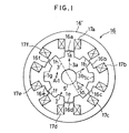
- a three-phase half-wave reluctance motor has a main body as shown in Fig. 1.
- the main body of the motor comprises a rotor 1 securely fitted on a rotary shaft 5 rotatably supported by bearings (not shown) provided in an unillustrated outer casing, and an armature (stator) 16 secured to the casing coaxially with the rotor, these two elements being each made of a laminate of silicon steel plates, as known in the art.
- the rotor 1 has eight salient poles la to lh formed on the outer peripheral surface thereof equidistantly in the circumferential direction with a phase difference of 360 degrees (electrical angle) between each other and each having a width corresponding to an electrical angle of 180 degrees (hereinafter, various angular parameters are expressed in the electrical angle).
- the stator 16 has an annular magnetic core 16' for forming magnetic paths, and six magnetic poles 16a to 16f each having a width of 180 degrees are formed on the inner peripheral surface of the magnetic core at equal distances in the circumferential direction such that the magnetic poles can be opposed to the salient poles la to lh with a gap of 0.1 to 0.2 mm, e.g., about 0.15 mm, therebetween.
- Exciting coils 17a to 17f are respectively fitted on the magnetic poles 16a to 16f.
- the exciting coils 17a and 17d are connected in series, and this pair will hereinafter be called a first-phase exciting coil pair K.
- the exciting coils 17b and 17e and the exciting coils 17c and 17f are connected in a similar fashion, and will hereinafter be called second- and third-phase exciting coil pairs L and M, respectively.
- the number of winding of one exciting coil in each pair is made larger than that of the other exciting coil in the same pair by a predetermined number.
- the opposed faces of the salient poles 1a to 1h and the magnetic poles 16a to 16f are different in width along the rotary shaft, to permit a leakage flux to be generated between the opposed faces and thereby make the output curve (mentioned later) of the motor even.
- the motor further comprises a position detection device shown in Fig. 3.
- the position detection device includes three position detecting elements 10a to 10c (Fig. 3) each having a diameter of 5 mm and comprising an air-core coil of about 100 turns, for detecting the rotational position of the salient poles 1a to 1h of the rotor 1. These detecting elements (hereinafter referred to as detection coils) are secured to the armature 16 at regular intervals of 120 degrees such that the coil faces thereof can be opposed to the side surfaces of the salient poles 1a to 1h with a gap therebetween.
- the position detection device further comprises an oscillator 7 with an oscillation frequency of about 1 to 5 MHz, the output side of which is connected to a bridge circuit composed of the detection coils 10a to 10c and resistors 15a to 15e.
- the bridge circuit is adjusted such that it is in equilibrium when none of the coils 10a to 10c are opposed to the salient poles 1a to 1h of the rotor 1.
- the bridge circuit is connected to flip-flop circuits (hereinafter referred to as FF circuits) 9a to 9c through low-pass filters composed of diodes 11a to 11d and capacitors 12a to 12d, operational amplifiers 13a to 13c, and differentiating circuits 8a to 8c, respectively.
- FF circuits flip-flop circuits
- the anodes of the diodes 11a to 11c are connected to connection nodes between the coils 10a to 10c and the resistors 15a to 15c, respectively, and the cathodes thereof are connected to respective ends of the capacitors 12a to 12c, which have other ends grounded, and also connected to respective positive input terminals of the operational amplifiers 13a to 13c.
- the anode of the diode 11d is connected to a connection node between the resistors 15d and 15e, and the cathode thereof is connected to one end of the capacitor 12d which is grounded at the other end, and also connected to the negative input terminals of the operational amplifiers 13a to 13c.
- the output terminals of the operational amplifiers 13a to 13c are respectively connected to the input terminals of the differentiating circuits 8a to 8c, the output terminals of which are respectively connected to the set input terminals of the FF circuits 9a to 9c as well as to the corresponding reset input terminals of same.
- the set output terminals of the FF circuits 9a to 9c are respectively connected to output terminals 6a to 6c of the position detection device.
- the motor further comprises a current supply control circuit shown in Fig. 4, for effecting and interrupting supply of an exciting current to the exciting coils 17a to 17f of the armature 16. i.e., the first- to third-phase exciting coil pairs K to M.
- Input terminals 4a to 4c of the current supply control circuit are respectively connected to the output terminals 6a to 6c of the aforesaid position detection device, and also connected to respective input terminals of AND circuits 14a to 14c of the current supply control circuit.
- the other input terminal of each of these AND circuits is connected to a reference voltage input terminal 40, to which a reference voltage is applied for variable control of the motor output torque, through an operational amplifier 40a which forms a chopper circuit in cooperation with the AND circuits.
- the output terminals of the AND circuits 14a to 14c are respectively connected through inverters to the bases of transistors (switching elements) 20a, 20c and 20e connected between a positive terminal 2a of a direct current power supply and the respective ends of the first- to third-phase exciting coil pairs K to M.
- the other ends of the first- to third-phase exciting coil pairs are connected to a negative terminal 2b of the direct current power supply and the negative input terminal of the operational amplifier 40a, through transistors 20b, 20d and 20f, respectively.
- a resistor 22 for detecting the exciting current flowing through the first- to third-phase exciting coil pairs, the other end of the resistor being connected to the anodes of diodes 21a, 21c and 21e.
- the cathodes of these diodes are connected to respective ends of the first- to third-phase exciting coil pairs K to M, which are connected at the other end to the positive terminal of the direct current power supply through diodes 21b, 21d and 21f, respectively.
- the bridge circuit of the position detection device (Fig. 3) provided in the motor is in equilibrium when none of the detection coils 10a to 10c are opposed to the salient poles 1a to 1h of the rotor 1. Accordingly, when the detection coil 10a is not opposed to any of the salient poles, the output of the low-pass filter composed of the diode 11a and the capacitor 12a is equal to the output of the low-pass filter composed of the diode 11d and the capacitor 12d, and therefore, the operational amplifier 13a generates a low-level output. In practice, however, when the rotation of the motor is stopped, any one of the detection coils is opposed to one of the salient poles.
- the impedance of the detection coil 10a is decreased due to the iron loss (eddy-current loss plus hysteresis loss) and thus the voltage drop at the resistor 15a becomes large, whereby the voltage applied to the positive input terminal of the operational amplifier 13a is increased and the output 25 of the same amplifier becomes high-level (the output is shown at 25a and 25b in Fig. 6). Namely, as the rotor 1 rotates, a rectangular-wave signal 25 is output from the operational amplifier 13a.
- the detection coils 10b and 10c are opposed to the side surfaces of any of the salient poles 1a to 1h, the voltage drops at the resistors 15b and 15c respectively become large, and accordingly, the outputs 26 and 27 (Fig. 6) of the operational amplifiers 13b and 13c become high-level due to an increase of the input voltages applied thereto through the low-pass filters 11b, 12b and 11c, 12c (the outputs are shown at 26a, 26b, 27a and 27b in Fig. 6). Accordingly, with rotation of the rotor 1, rectangular-wave signals 26 and 27 are respectively output from the operational amplifiers. The above rectangular-wave signals 25 to 27 are shifted in phase from each other by 120 degrees.
- the differentiating circuits 8a to 8c generate pulse signals (indicated at 31a, 31b, 32a, 32b, 33a and 33b in Fig. 6) upon detecting the rise of the outputs 25 to 27 of the operational amplifiers.
- the FF circuits 9a to 9c, to which these pulse signals are input, are reset when the power of the motor is turned on, and accordingly low-level outputs appear at the output terminals 6a to 6c of the position detection device.
- a high-level output 25a is supplied from the operational amplifier 13a, a pulse signal 31a is generated and a high-level output appears at the output terminal 6a.
- a pulse signal 32a is supplied to the reset input terminal of the FF circuit 9a, whereby the output from the output terminal 6a of the position detection device becomes low-level. Simultaneously, the pulse signal 32a is supplied to the set input terminal of the FF circuit 9b, and therefore, the output from the terminal 6b becomes high-level.
- a pulse signal 33a is thereafter generated and supplied to the reset input terminal of the FF circuit 9b and the set input terminal of the FF circuit 9c, the outputs from the terminals 6b and 6c become low-level and high-level, respectively.
- rectangular-wave outputs i.e., signals representing the positions of the salient poles of the rotor relative to the first- to third-phase exciting coil pairs K to M, are delivered from the output terminals 6a to 6c of the position detection device.
- signals are indicated by curves (rectangles) 28 to 30 in Fig. 6 and will hereinafter be referred to as first- to third-phase position detection signals.
- a high-level second-phase position detection signal 29a for example, is supplied from the position detection device to the input terminal 4b of the current supply control circuit (Fig. 4)
- this high-level signal 29a is supplied to the base of the transistor 20d, while a high-level output from the AND circuit 14b, which is then in an open state, is converted into a low-level output by the inverter and then applied to the base of the transistor 20c.
- the transistors 20c and 20d are rendered conductive, permitting an electric current to pass the exciting coils 17b and 17e (the second-phase exciting coil pair L).
- the magnetic poles 16b and 16f of the armature 16 are magnetized and the salient poles 1b and 1f are magnetically attracted, so that the rotor 1 is rotated in a direction indicated by arrow A-1 in Fig. 1.
- the second-phase position detection signal 29 becomes low-level and simultaneously a high-level third-phase position detection signal 30a is supplied to the input terminal 4c of the current supply control circuit.
- the current supply to the exciting coil pair L is interrupted while an electric current is supplied to the exciting coil pair M.
- the current supply to the exciting coil pair M is interrupted and a current is supplied to the exciting coil pair K.
- the current supply mode cyclically changes in order of the exciting coil pair K, the exciting coil pair L and the exciting coil pair M, with every rotation over 120 degrees, whereby the exciting coil pairs K to M are sequentially and continuously supplied with an electric current and the motor generates an output torque.
- the axially symmetrical magnetic poles are magnetized to act as N and S poles, as shown in Fig. 2. Since the excited two magnetic poles are always of opposite polarities, the leakage flux passes the unexcited magnetic poles in opposite directions, thus eliminating the generation of counter-torque.
- the magnetic energy stored in the exciting coil pair K is discharged in the form of electric current through the diode 21a, the transistor 20b and the resistor 22, and after this, when the current is reduced to a predetermined value determined by the hysteresis characteristic of the operational amplifier 40a, the output of this operational amplifier becomes high-level and the transistor 20a is turned on again, permitting the passage of the exciting current.
- the operational amplifier 40a cooperates with the AND circuit 14a to turn on and off the transistor 20a in accordance with the relationship between the values of the exciting current and the above preset value, thereby controlling the exciting current and thus the output torque of the motor.
- the operational amplifier 40a functions, in cooperation with the AND circuits 14a to 14c, as a chopper circuit.
- the torque is reduced (namely, reduced-torque occurs, as hereinafter called) in the former half of the curve 34 and a large counter-torque is produced in the latter half of same, and therefore, the conventional motor is low in efficiency and in rotational speed.
- the motor according to the embodiment eliminates these disadvantages, as stated below.
- an electric current is supplied to the second-phase exciting coil pair L in response to generation of the second-phase position detection signal 29a
- the exciting current quickly rises, as indicated by a current supply curve (dashed curve) 34b in Fig. 5, due to a high voltage applied from the direct current power supply terminal 2a, whereby the occurrence of reduced-torque is eliminated.
- a current supply curve dashexing current supplied to the second-phase exciting coil pair L in response to generation of the second-phase position detection signal 29a
- the exciting current quickly rises, as indicated by a current supply curve (dashed curve) 34b in Fig. 5, due to a high voltage applied from the direct current power supply terminal 2a, whereby the occurrence of reduced-torque is eliminated.
- a direct current power supply with a higher terminal voltage is used to thereby shorten the width of the rising portion of the current supply curve.
- both the transistors 20a and 20b are turned off, and an electric current flows through a path from the diode 21b to the power supply terminals 2a and 2b, to the resistor 22, and to the diode 21a, namely, the energy flows back to the power supply, due to the magnetic energy stored in the exciting coil pair K.
- the exciting current is quickly decreased (see the falling portion of the curve 34 relating to the second-phase signal 29a).
- the magnetic energy thus returned is, in general, stored in a large-capacitance rectifying capacitor incorporated in the direct current power supply.
- the higher the power supply voltage the shorter the width (indicated by arrow 37a) of the falling portion of the current supply curve 34, and when the width of the falling portion is not greater than 30 degrees, no substantial counter-torque is caused.
- the other current supply curves 34b and 34c In the case of rotating the motor at a high speed, a direct current power supply with a higher terminal voltage is used, to shorten the width of the falling portion of the current supply curve, which becomes shorter with decrease in the width of the position detection signal.
- the maximum allowable rotation speed of the motor can be determined by the value of the direct current power supply voltage, and that the output torque of the motor can be controlled in accordance with the value of the reference voltage applied to the reference voltage input terminal 40. Namely, the maximum rotational speed and the output torque of the motor can be controlled independently.
- the motor of this embodiment can provide an even output torque characteristic.
- the widths of the salient poles 1a to 1h of the rotor 1 along the axis of the rotary shaft differ from those of the magnetic poles 16a to 16f of the armature 16, as mentioned above, and accordingly, a leakage flux is produced between the opposed faces of the salient poles and the magnetic poles, which contributes to leveling the output torque of the motor after time B, as indicated by dashed curves 41a to 41c.
- the output characteristic varies from the curve 41a toward the curve 41c, gradually narrowing the width of the flat portion.
- the positions of the detection coils 10a to 10c are adjusted such that the time for starting the current supply is advanced, namely, the current supply is started near the rise of the torque curve, whereby even and large output torque is obtained, as indicated by exciting current curves (dashed curves) 35a to 35c in Fig. 5.
- arrows 38 and 39 respectively denote the width (120 degrees) of a high-level first-phase position detection signal 29a and the width (180 degrees) in which positive torque is obtained.
- the width of the interval 39a is twice as long as that of the interval 37a (this is the case with the curves 35a and 35c), and accordingly, the flat portion of the output torque is prolonged, ripple of the output torque is reduced, and the motor can be rotated at a high speed.
- the exciting coils associated with each pair of magnetic poles arranged symmetrically about the rotary shaft 5 have different numbers of winding to prevent vibration.
- the magnetic forces exerted, e.g., by the magnetic poles 16a and 16d to radially attract the salient poles 1a and 1e are ideally canceled out, and the attractive force acting in the circumferential direction serves to produce an output torque.
- the rotor 1 since the radial attractive forces are extremely strong, if there is even a slight dimensional difference in the gaps between the individual magnetic poles and the salient poles opposed thereto or even a slight machining error exists in the bearings of the rotary shaft 5, the rotor 1 receives a force acting in the direction indicated by arrow 3a or in the opposite direction and accordingly is vibrated during rotation of the rotor 1.
- the salient poles 1a to 1h of the rotor 1 are opposed to the magnetic poles 16a to 16f of the armature 16 with a gap as small as about 0.15 mm, and therefore, such vibration should desirably be eliminated.
- the number of winding of one exciting coil in each pair i.e., the exciting coils 17a, 17b and 17c
- the exciting coils 17a, 17b and 17c is increased by a predetermined number than that of the other exciting coil in the same pair, i.e., the exciting coils 17b, 17e and 17f, and an electric current is sequentially passed through the exciting coil pairs K to M, whereby the rotor 1 receives only those forces acting in directions indicated by arrows 3a, 3b and 3c during the rotation thereof.
- the motor of this embodiment can be operated with a direct current power supply having a lower terminal voltage, e.g., a battery, compared to the motor of the first embodiment, and therefore can be used as a drive source for an electric vehicle which uses a battery as a power supply, unlike the first embodiment.
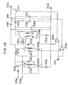
- the reluctance motor of the second embodiment has a current supply control circuit shown in Fig. 7, instead of the circuit of Fig. 4, and this current supply control circuit comprises, in place of the operational amplifier 40a and the AND circuits 14a to 14c, a diode 18 and a capacitor 19 for the prevention of reverse current.
- the exciting current takes a value equal to the quotient obtained by dividing the difference between the voltage across the direct current power supply terminals 2a and 2b and a counter electromotive force proportional to the output torque curves 41a to 41c shown in Fig. 5, by the resistance value of the exciting coils. Accordingly, the exciting current maintains a substantially constant value in an intermediate portion of the current supply period in which the counter electromotive force is even. In the latter half of the current supply period in which the counter electromotive force is decreased, on the other hand, the exciting current increases and thus the output torque is increased, whereby a torque reduction in the latter half of the output torque curve is compensated.
- the second position detection signal 29a is input to the input terminal of the current supply control circuit and the transistors 20c and 20d are rendered conductive, the direct current power supply voltage and the voltage of the charged capacitor 19 are both applied to the second-phase exciting coil pair L. Consequently, the exciting current flowing through the exciting coil pair L quickly rises, as indicated by the curve 35b in Fig. 5, and thereafter is maintained at a substantially constant value, as described above. This is the case with the third-phase exciting coil pair M.
- the capacitance of the capacitor 19 is small, the widths of the rising and falling portions of the exciting current are correspondingly small, whereby the occurrence of reduced-torque and counter-torque during high-speed operation of the motor can be prevented, namely, the motor can be operated at a high speed and with high efficiency.
- the capacitor 19 may be omitted.
- the backflow of the stored magnetic energy to the smoothing capacitor incorporated in the direct current power supply is prevented by the reverse current-preventing diode 18, and the stored magnetic energy is supplied through the capacitor 19 to the next exciting coil to which an electric current is being supplied, so that the magnetic energy is quickly discharged from one of adjacent exciting coils and is quickly stored in the other. Therefore, the voltage of the direct current power supply may be low.
- the time required for the extinction and storage of the aforesaid magnetic energy is shorter than 20 ⁇ sec, permitting the motor to be operated at a speed of 100,000 revolutions per minute.
- the capacitance of the capacitor is preferably set to a value large enough to reliably prevent the occurrence of counter-torque, to thereby reduce the eddy-current loss, which is a factor of the iron loss, and to improve the efficiency.
- a three-phase reluctance motor according to a third embodiment of this invention will be described with reference to Figs. 8 to 11.
- the motor of this embodiment comprises a main body (Fig. 8) basically identical in arrangement with that of the motor shown in Fig. 1, and detection coils 110a to 110c (Fig. 9) corresponding to the detection coils 10a to 10c in Fig. 2.
- the main body of the motor comprises a rotor 101 having seven salient poles 101a to 101g, an armature 116 having six magnetic poles 116a to 116f to which exciting coils 117a to 117f are respectively fitted, and a rotary shaft 105.
- the motor also comprises a position detection device (Fig. 10) corresponding to the position detection device shown in Fig. 3, which device includes a bridge circuit in association with the first detection coil 110a, composed of this detection coil and resistors 115a to 115c.
- a low-pass filter composed of diodes 111a and 111b and capacitors 112a and 112b, an operational amplifier 113, and a logic circuit 118 comprising a circuit usually used for a control circuit of a three-phase Y-connection semiconductor motor and including six output terminals 118a to 118f.
- the diode 111a in the low-pass filter has an anode connected to a connection node between the coil 110a and the resistor 115a, and has a cathode connected to one end of the capacitor 112a, the other end of which is grounded, and to the positive input terminal of the operational amplifier 113.
- the other diode 111b has an anode connected to a connection node between the resistors 115b and 115c, and a cathode connected to one end of the capacitor 112b, the other end of which is grounded, and the negative input terminal of the operational amplifier 113.
- the output terminal of the operational amplifier 113 is connected to an input side of the logic circuit 118 and an input terminal of an inverter 113a provided between the operational amplifier 113 and the logic circuit 118.
- numerals 114a and 114b denote circuits associated with the coils 110b and 110c, respectively, which are each composed of elements corresponding to the bridge circuit, the low-pass filter, and the operational amplifier associated with the coil 110a, and are connected to a common oscillator 110 corresponding to the element 7 in Fig. 3.
- Numerals 113b and 113c denote inverters individually corresponding to the inverter 113a.
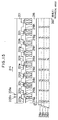
- the motor further comprises a current supply control circuit (Fig. 11) corresponding to the circuit of Fig. 4.
- Input terminals 155a to 155f of the current supply control circuit are respectively connected to output terminals 118a to 118f of the position detection device.
- the input terminals 155a to 155c are connected to the bases of transistors 120b, 120d and 120f, respectively, and also connected through inverters to the bases of three transistors (switching elements) 120a, 120c and 120e, respectively, the emitters of which are connected to a positive terminal 102a of the direct current power supply through a diode 149a and a transistor 141a.
- the collectors of the switching transistors 120a, 120c and 120e are connected to respective ends of the exciting coils 117a, 117c and 117e, which have other ends connected to a negative terminal 102b of the direct current power supply through corresponding ones of the switching transistors 120b, 120d and 120f and an exciting current detection resistor 122a.
- a diode 121a is connected to a series connection of the exciting coil 117a and the transistor 120b, and a diode 121b is connected to a series connection of the same exciting coil and the transistor 120a.
- diodes 121c and 121d and diodes 121e and 121f are respectively connected to the exciting coils 117c and 117e.
- a connection node between the resistor 122a and the transistors 120b, 120d and 120f is connected to the positive input terminal of an operational amplifier 140a, whose negative input terminal is connected to a reference voltage input terminal 140 to which a reference voltage is applied for a variable control of the exciting current (motor output torque), and the output terminal of the operational amplifier 140a is connected to the base of a transistor 141a which cooperates with the amplifier 141a to function as a chopper circuit mentioned later.
- the exciting coils 117b, 117d and 117f similarly include various circuit elements equivalent to those described above with reference to the exciting coils 117a, 117c and 117e, as indicated by symbols D to F in Fig. 11.
- Reference numerals 122b, 140b, 141b, 148a, 148b and 149b respectively correspond to the aforementioned elements 122a, 140a, 141a, 147a, 147b and 149a.
- any one of the detection coils 110a to 110c is opposed to one of the salient poles 101a to 101g of the rotor 101.
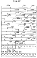
- the output 125 of the operational amplifier 113 becomes high-level (indicated at 125a and 125b in Fig. 12), as in the case of the first embodiment. Namely, as the rotor 101 rotates, a rectangular-wave signal 125 is output from the operational amplifier 113.
- numeral 126 denotes the output of the inverter 113a.
- the output 127 or 129 of an unillustrated operational amplifier included in the blocks 114a and 114b, respectively, becomes high-level (indicated at 127a, 127b, 129a and 129b in Fig. 12), and a rectangular-wave signal 127 or 129 is output from the operational amplifier as the rotor 101 rotates.
- Rectangular-wave signals 128 and 130 are output from the inverters 113b and 113c, respectively.
- the rectangular wave signals 125, 127 and 129 are shifted in phase from each other by 120 degrees. This is the case with the signals 126, 128 and 130.
- rectangular-wave position detection signals 131 to 136 representing the rotational position of the rotor are respectively output (Fig. 12).
- the signals 131 and 134, the signals 132 and 135, and the signals 133 and 136 respectively have a phase difference of 180 degrees, and the signals 131 to 133 and the signals 134 to 136 respectively have a phase difference of 120 degrees.
- the current supply mode varies with every 60-degree rotation of the rotor 101, in other words, the excited magnetic poles of the armature cyclically change in order of the magnetic poles 116b (N pole) and 116c (S pole), the magnetic poles 116c (S pole) and 116d (N pole), the magnetic poles 116d (N pole) and 116e (S pole), the magnetic poles 116e (S pole) and 116f (N pole), and the magnetic poles 116f (N pole) and 116a (S pole).
- the rotor 101 is driven in the direction of arrow A-3.
- the excited two magnetic poles are always of opposite polarities, and therefore, the leakage flux passes the unexcited magnetic poles in opposite directions, thereby preventing the occurrence of counter-torque.
- the current supply to the exciting coil 117a is started. Similar to the case of the first embodiment, the delay at the rising portion (indicated at 137a) of the exciting current passing the exciting coil 117a, caused due to the inductance of the coil, is reduced by use of the high voltages at the direct current power supply terminals 102a and 102b.
- the operational amplifier 140a cooperates with the transistor 141a to control the exciting current, i.e., the output torque of the motor, in accordance with the relation between the exciting current and the aforesaid preset value.
- the operational amplifiers 140a and 140b cooperate with the transistors 141a and 141b, respectively, to function as a chopper circuit. Accordingly, as in the cases of the above embodiments, the maximum operating speed and the output torque of the motor can be controlled independently.
- the chopping frequency determined mainly by the capacitances of the capacitors 147a and 147b is invariable, unlike a conventional unstable chopper circuit whose chopping frequency is varied with changes in the impedance of the exciting coils caused by changes in the amount of the magnetic flux passing the magnetic poles.
- the operation of the chopper circuit has no connection with the direct current power supply voltage, and accordingly, is in no way affected by fluctuation of the same. It is therefore unnecessary to use a large-capacitance capacitor for the purpose of rectification, in a power supply using a rectifying capacitor for obtaining a direct current from an alternating current, particularly in a three-phase power supply, thereby simplifying the construction of the power supply.
- the width of the alternating current power supply voltage contributing to the current supply of the exciting current is about two-thirds the width of half-period of the alternating current power supply voltage. Accordingly, unlike the conventional case of using a converter for achieving a pulsed current supply close to the peak voltage, it is possible to broaden the width of current supply with respect to the alternating current power supply and to eliminate the occurrence of mechanical and electrical noises.
- the magnetic energy stored in the exciting coil 117a is discharged in the form of an electric current through a path from the diode 1221b, to the capacitor 148a, to the resistor 122a, to the diode 121a, and to the exciting coil 117a, and accordingly, the exciting current flowing through the coil 117a is quickly decreased, as indicated by the dashed line 137b, and the capacitor 148a is charged.
- the diode 149a serves to prevent the current flow to the direct current power supply caused due to the stored magnetic energy.
- the voltage of the charged capacitor is applied to the exciting coil 117c, thereby quickly rising the exciting current supplied to this coil.
- both the width of the falling portion of the exciting current passing the coil 117a and the width of the rising portion of the exciting current passing the coil 117c are no greater than an electrical angle of 30 degrees, at which counter-torque is generated.
- the exciting current for the coil 117a varies as indicated at 139b, due to the chopper control achieved by the operational amplifier 140a and the transistor 141a. Thereafter, in response to the generation and extinction of the high-level position detection signal 133a, the current supply to the exciting coil 117e is controlled in the same manner as described above.
- Similar current supply control is effected also at the generation and extinction of the position detection signals 134 to 136.
- the chopper control is effected by the operational amplifier 140b and the transistor 141b, while the capacitor 147b is charged and discharged and an exciting current flows through the exciting coils 117b, 117d and 117f.
- curves 117a' to 117f' denote torques generated by the current supply to the exciting coils 117a to 117f, respectively, with lapse of time
- curve 144 denotes a torque generated by the current supply to the first exciting coil group including the exciting coils 117a, 117c and 117e
- curve 145 denotes a torque generated by the current supply to the second exciting coil group including the exciting coils 117b, 117d and 117f.
- Numerals 144a and 145a denote torque generation periods relating to the exciting currents flowing through the coils 117c and 117d, respectively.
- the output torque produced by the motor is equal to the composite of the torques 144 and 145 and, like the output torque of a three-phase Y-connection semiconductor motor, has a small fluctuation with lapse of time.
- Curve 146 denotes an exciting current characteristic of a conventional reluctance motor, wherein the exciting current has a small value at the initial stage of current supply due to the inductance of the exciting coil, and has a still smaller value at the intermediate stage due to the counter electromotive force.
- the exciting current at the last stage of current supply which is suddenly increased with a reduction in the counter electromotive force, does not contribute to the generation of output torque of the motor, rather it causes a Joule loss, and as indicated by a dashed line 146a, a counter-torque is produced due to the discharged magnetic energy.
- an extremely large torque 142 is generated when a salient pole of the rotor approaches a position facing a magnetic pole of the armature, while the torque is reduced when the salient pole moves away from the magnetic pole.
- the width of the salient poles along the axis of the rotary shaft differs from that of the magnetic poles, like the first embodiment, whereby an even output torque characteristic 142 can be obtained.
- the rotor 201 is rotated by the magnetic attractive forces produced by a pair of adjacent magnetic poles, and accordingly, the vector of the force acting in the radius direction between the magnetic pole and the salient pole rotates synchronously with the rotation of the rotor, whereby during rotation of the rotor, the rotary shaft 205 is always pushed against the bearings and thus is not vibrated.
- a two-phase reluctance motor according to a fourth embodiment of this invention will be described with reference to Figs. 14 to 16.
- the motor has a main body basically similar in arrangement to those shown in Figs. 1 and 8, and the main body comprises, as shown in Fig. 14, a rotor 201 fitted on a rotary shaft 205 and having ten salient poles 201a to 201j, and an armature 216 having eight magnetic poles 216a to 216h, to which exciting coils (only two exciting coils are illustrated at 217a and 217b) are respectively fitted, and an annular magnetic core 216'.
- the exciting coils are formed by thick electric wire to reduce the copper loss and thus improve the efficiency of the motor, and to permit a required magnetic flux to be produced in a reluctance motor having no field magnet, a space large enough to contain large exciting coils is provided.
- the exciting coils 217a and 217e are connected in series or in parallel, and this pair is hereinafter called the first exciting coil pair K' (Fig. 16).
- the exciting coils 217b and 217f, the exciting coils 217c and 217g, and the exciting coils 217d and 217h are respectively connected to each other, and these pairs will hereinafter be called the second to fourth exciting coil pairs L', M' and S' (Fig. 16), respectively.
- the motor includes a position detection device having a basically identical arrangement to that shown in Fig. 10.
- This device does not have elements corresponding to the logic circuit 118, the block circuit 114b and the inverter 113c in Fig. 10, and has detection coils 208a and 208b shown in Fig. 15, instead of the detection coils 110a and 110b.
- These detection coils which are identical to those shown in Fig. 9, are spaced from each other by an electrical angle of 90 degrees and arranged such that they can be opposed to the side surfaces of the salient poles 201a to 201j.
- the detection coils 208a and 208b are adapted to generate a position detection signal when a salient pole is at about 30 degrees before a magnetic pole, for the purpose mentioned later.
- the motor further comprises a current supply control circuit shown in Fig. 16.
- Fig. 16 unlike the circuit of Fig. 11 wherein the current supply to the exciting coils is controlled in accordance with six different position detection signals, the current supply to the four pairs of exciting coils is controlled in accordance with four different position detection signals, but the arrangement of the circuit is fundamentally identical to that shown in Fig. 11, and accordingly, a detailed description is omitted.
- the elements are numbered in a manner similar to that of Fig. 11, for instance, the element 202a corresponds to the element 102a in Fig. 11.
- a block indicated by symbol C' includes the two exciting coil pairs M' and S' and their peripheral elements.
- the current supply control circuit controls the current supply to the first to fourth exciting coil pairs K' to S', in accordance with the output and the inverted output of the detection coil 208a, the output and the inverted output of the detection coil 208b, and position detection signals 271 to 274, input respectively to input terminals 255a to 255d thereof.
- a curve 224a represents the rising portion of the exciting current flowing through the coil pair L' in accordance with the high-level position detection signal 273a.
- the exciting currents relating to the signals 272a and 274a rise and fall as indicated by the dashed lines.
- the width of the current supply is larger than 180 degrees as a result of the discharging of the magnetic energy stored in the exciting coils, giving rise to the possibility of counter-torque being caused. Therefore, the detection coils 208a and 208b are arranged on a side advanced by about 30 degrees, as mentioned above, to advance the time of starting the current supply and thereby prevent the occurrence of counter-torque.
- the motor of this embodiment comprises a position detection device (not shown) similar to the device shown in Fig. 10 and also similar to the position detection device used in the fourth embodiment, and a current supply control circuit shown in Fig. 19.
- the position detection device includes a plurality of OR circuits for generating position detection signals 382 to 385 (Fig. 17) corresponding respectively to the logical sum of the position detection signals 271 and 274 in the fourth embodiment, the logical sum of the signals 271 and 272, the logical sum of the signals 272 and 273, and the logical sum of the signals 273 and 274, the signals produced being supplied to input terminals 355a to 355d of the current supply control circuit, respectively.
- Position detection coils corresponding to the elements 208a and 208b in Fig. 15, respectively, are arranged such that the middle of the generation period of each high-level position detection signal coincides with the time at which the motor output torque produced as a result of the current supply to the individual exciting coils is maximum.
- the motor operates basically in the same manner as that according to the fourth embodiment. Namely, an electric current is sequentially supplied to the four exciting coil pairs K', M', L' and S' in the order mentioned, over an electrical angle of 90 degrees for each, in accordance with the aforesaid position detection signals 382 to 385.
- the motor is therefore capable of high-torque, high-speed operation with a high efficiency.
- a high-level position detection signal 382a (Fig. 17)
- the current supply to the exciting coil pair K' is started and accordingly the exciting current rises as indicated by a curve 323a (Fig. 18).
- the chopper control of the exciting current is effected by an operational amplifier 350 and a transistor 341, and a capacitor 347 is charged and discharged in accordance with this control action, as in the cases of the above-described embodiments.
- the current supply to the exciting coil pair M' is started in accordance with a position detection signal 383a generated simultaneously with the extinction of the signal 382a.
- the magnetic energy stored in the exciting coil pair K' is utilized for the storage of magnetic energy in the exciting coil pair M', thereby shortening the fall time of the exciting current flowing through the coil pair K' indicated at 323, and the rise time of the exciting current supplied to the coil pair M'.
- the exciting current supplied to the coil pair M' quickly rises as indicated by a dashed line 323c.
- the width of the period 323 can be varied by selecting the capacitance of the capacitor 348, and is set to a value suited to the operating speed of the motor.
- the exciting current is maintained at a preset value during the current supply period, and is quickly decreased with the extinction of the position detection signal 383a.
- the current supply control is similarly effected with respect to the exciting coil pairs L' and S'.
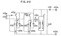
- the motor of this embodiment comprises a current supply control circuit (Fig. 20) which is fundamentally identical in arrangement with that shown in Fig. 19 but which differs therefrom in that it has no chopper circuit and thus is simpler in arrangement.
- Fig. 20 similar numbering is employed to denote like elements appearing in Fig. 19, for example, numeral 455a represents the element corresponding to the element 355a in Fig. 19.
- This motor can be operated by a low-voltage power supply, such as a battery power supply, and therefore is suitably used as a drive source for a compact electric car.
- the motor is used as a mere drive source on which an accurate output torque control is not performed.
- the exciting current rises along a curve corresponding to the curve 323a.
- the rise time of the exciting current is long because of a large inductance of the exciting coil pair K', but an exciting current large enough to rotate the motor at a low speed and corresponding to the supply voltage from direct current power supplies 402a and 402b is passed, whereby the motor is started.
- a position detection signal corresponding to the signal 383a is supplied to the input terminal 455c, and an electric current is supplied to the exciting coil pair M'. Thereafter, the motor is accelerated with the application of position detection signals corresponding to the signals 384a and 385a.
- transistors 420a and 420b are turned off.
- the magnetic energy stored in the exciting coil pair K' is discharged with lapse of time in the form of an electric current varying along a curve corresponding to the curve 323b. Due to the action of a diode 449 and a capacitor 448, however, most part of the discharged magnetic energy flows to the exciting coil pair M' which is turned on by then. As a result, the exciting current flowing through this coil pair quickly rises along a curve corresponding to the curve 323c, whereby the occurrence of reduced-torque and counter-torque is suppressed and a high-speed operation of the motor is permitted.
- the motor of this embodiment comprises a current supply control circuit, shown in Fig. 21, which includes a chopper circuit, unlike the current supply control circuit of Fig. 20.
- the chopper circuit differs from the counterparts in the foregoing embodiments in that it uses a monostable circuit.
- the numbering of the elements in Fig. 21 is similar to that of Fig. 20.
- a high-level output is sent from the operational amplifier 550 to a monostable circuit 503.
- the monostable circuit which is driven by this high-level output, generates a high-level output which is inverted by an inverter and then applied to one input terminal of an AND circuit 506a.
- the AND circuit 506a is closed, so that the supply of the high-level position detection signal is interrupted and a transistor 520b is turned off, whereby the exciting current is reduced.
- the output of the monostable circuit 503 turns to low-level after the lapse of a predetermined time, and therefore, the AND circuit 506a is opened and the transistor 520b is rendered conductive, whereby the exciting current is increased.
- the aforesaid operation is repeatedly carried out by a chopper circuit composed of the operational amplifier 550, the monostable circuit 503 and the AND circuit 506a, so that the exciting current is controlled to the reference voltage applied to the reference voltage terminal.
- a similar control is effected with respect to the other exciting coil pairs L", M" and S", by chopper circuits composed of the elements 550 and 503, an AND circuit 506b, and AND circuits (not shown) incorporated in a block C" and respectively connected to input terminals 507a and 507b.
- a three-phase reluctance motor according to an eighth embodiment of this invention will be described with reference to Figs. 22 to 27.
- the feature of this motor resides in that the main body is small-sized and flat in shape, and that the arrangement is simplified by using two, not three, position detecting elements.
- the main body of the motor has a base plate 603, and a rotary shaft 604 is rotatably supported by ball bearings 605 and 606 which are arranged in a cylindrical member 610 fitted into a hole bored through a central portion of the base plate 603.
- a cup-shaped rotating member 602, which is made of soft steel, is secured at the center thereof to an upper end of the rotary shaft 604, and a rotor 601 is secured to the inner peripheral surface of the rotating member 602.
- the rotating member 602 may be made of an aluminum plate so that the eddy-current loss mentioned later, and thus, the position detection output may be increased.
- the rotor 601 and a stator 616 each made of a laminate of silicon steel plates, have seven salient poles 601a to 601g and six magnetic poles 616a to 616g, respectively, facing each other with a gap of about 0.15 mm.
- the widths of the salient poles and magnetic poles are respectively set to 20 mm and 15 mm, for example.
- Exciting coils 617a to 617f are respectively fitted to the magnetic poles.
- a ring magnet 609 is secured to the bottom surface of a bent portion 614 extending from the peripheral wall of the rotor 601 and has forty N poles and forty S poles (Fig. 24).
- Numeral 611 denotes the N and S poles omitted from the figure.
- An induction coil 613 (Fig. 25) is arranged on a surface portion of the base plate 603 facing the magnet 609, and comprises an alternately bent conductor formed by a printed wiring technique.
- Numeral 612 denotes the portion of the conductor omitted from Fig. 25.
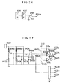
- the magnet 609 and the induction coil 613 constitute a frequency generator (indicated at 656 in Fig. 26) for generating an electrical signal whose frequency is proportional to the rotational speed of the rotating member 602.
- the output terminal of the frequency generator 656 is connected to an input terminal of a frequency-voltage converter 657, whose output terminal is connected to a negative input terminal of an operational amplifier 658 which is supplied at a positive input terminal with a reference positive voltage representing a preset rotational speed from a terminal 659.
- An output terminal 658a of the operational amplifier 658 is connected to a terminal corresponding to the reference voltage terminal 140 of the current supply control circuit in Fig. 11.
- the motor further comprises a position detection device shown in Fig. 27, which includes detection coils 608a and 608b secured to the base plate 603.
- the stepped conductors are formed by pressing and each have a width of 120 degrees, wherein the conductor 614a is the remotest from the detection coils and the conductor 614c is the closest to the same.
- symbol R denotes the stepped conductors omitted from the figure.
- the detection coils 608a and 608b cooperate with resistors 643a to 643d to form bridge circuits, respectively, each bridge circuit being connected at an input side to an oscillator 607 having an oscillation frequency of 1 to 5 MHz and connected at an output side to corresponding ones of operational amplifiers 646a and 646b through a low-pass filter composed of a capacitor and a diode.
- the output terminal of the operational amplifier 646a is connected to the positive input terminals of operational amplifiers 618a to 618c, the negative input terminals of which are connected to a reference voltage terminal 640.
- numerals 640a to 640c denote resistors serving as a voltage divider.
- the output terminal of the operational amplifier 618a is connected to an output terminal 623a of the position detection device and also connected through an inverter to one input terminal of an AND circuit 619a.
- the output terminal of the operational amplifier 618b is connected to the other input terminal of the AND circuit 619a and also connected through an inverter to one input terminal of an AND circuit 619b.
- the output terminal of the operational amplifier 618c is connected to the other input terminal of the AND circuit 619b.
- the output terminals of the AND circuits 619a and 619b are respectively connected to output terminals 623b and 623c of the position detection device.
- the output terminal of the operational amplifier 646b is connected to an input side of a block B' including elements corresponding to the aforesaid various elements 618a to 618c, 619a, 619b, and 640a to 640c.
- the block B' is connected at an output side to output terminals 623d to 623f of the position detection device.
- the motor comprises a current supply control circuit (not shown) having the same arrangement as the current supply control circuit shown in Fig. 11, and this circuit has six input terminals connected to the aforesaid terminals 623a to 623f of the position detection device, respectively.
- the motor according to the eighth embodiment shown in Figs. 22 to 27, operates in substantially the same manner as the above-described motor of the third embodiment, and accordingly, the operation thereof will be described briefly.
- the voltage applied to the positive input terminal of the operational amplifier 658 is higher than that applied to the negative input terminal of same, and thus, the voltage applied to the reference voltage input terminal (corresponding to the terminal 140 in Fig. 11) of the current supply control circuit rises to a maximum. Accordingly, the exciting current is at a maximum level, thus improving the starting characteristics of the motor.
- the voltage applied to the negative input terminal of the operational amplifier 658 approaches the voltage applied to the positive input terminal of same. Accordingly, the output of the operational amplifier, which determines the exciting current, is correspondingly decreased, whereby the motor is operated at a constant speed to produce an output torque corresponding to a load.
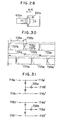
- a magnetic attractive force is produced between the salient poles of the rotor and the magnetic poles of the armature, thereby obtaining an output torque of the motor.
- a force rotating the salient pole 601a is produced by the interaction between magnetic fluxes P, G and H shown in Fig. 28. These fluxes are considered leakage fluxes.
- the dashed arrows represent magnetic fluxes passing behind the salient pole 601a.
- the detection coil 608a comes to a position opposed to the conductor 614a
- the voltages applied to the positive input terminals of the operational amplifiers 618a to 618c from the operational amplifier 646a become higher than the voltages applied to the negative input terminals of the amplifiers 618a to 618c, and thus the operational amplifiers 618a to 618c produce high-level outputs.
- the AND circuits 619a and 619b are closed, and a high-level position detection signal is output only from the output terminal 623a of the position detection device.
- the detection coil 608a becomes opposed to the conductor 614c
- the voltages applied to the positive input terminals of the operational amplifiers 618a to 618c become lower than the voltages applied to the negative input terminals of the operational amplifiers 618a and 618b, but are higher than the voltage applied to the negative input terminal of the operational amplifier 618c, whereby a high-level position detection signal is output only from the output terminal 623c.
- a high-level position detection signal having a width of 120 degrees is output sequentially from the terminals 623d to 623f.
- the motor operates thereafter in the same manner as the third embodiment described with reference to Figs. 12 and 13, and accordingly, the description is omitted.
- the motor of this embodiment is suitable for a drive source for driving a floppy disk, for example.
- a motor according to a ninth embodiment of this invention comprises a main body, position detecting elements and a position detection device (neither is shown), which are respectively identical in arrangement to the main body, the position detecting elements and the position detection device shown in Figs. 8 to 10, and also comprises a current supply control circuit shown in Fig. 29.
- the current supply control circuit is equivalent to the circuit shown in Fig. 11, except that it has no chopper circuit.
- Fig. 29 the numbering of the elements is similar to that of Fig. 1.
- the motor of this embodiment operates fundamentally in the same manner as that of the third embodiment shown in Figs. 8 to 11.
- Fig. 30, similar to Fig. 13, shows changes in the exciting current according to the current supply control, with lapse of time.
- numerals 718a, 718c, 718d and 718f represent corresponding ones of the output terminals 118a to 118f of the position detection device in Fig. 10, and numerals 718a' to 718f' represent terminals respectively connected to input terminals 755a to 755f of the current supply control circuit in Fig. 29.
- the terminal 718a is connected to the terminal 718a' and the anode of a diode, which in turn is connected to the terminal 718b' through an inverter 708a.
- the terminal 718c is connected to the terminal 718c' and also to the anode of a diode which in turn is connected to the terminal 718b' through the inverter 708a.
- terminal 718d is connected to the terminal 718d' and also connected through a diode and an inverter 708b to the terminal 718e'
- terminal 718f is connected to the terminal 718f' and also connected through a diode and the inverter 708b to the terminal 718e'.
- a high-level position detection signal is output from the terminal 718b' except when a high-level position detection signal is output from the terminals 718a' and 718c' to the current supply control circuit, and a position detection signal is output from the terminal 718e' except when the position detection signal is output from the terminals 718d' and 718f'. Consequently, a series of signals are delivered without interruption.
- numerals 713, 714a, 714b, 718, and 718a to 718f denote elements respectively corresponding to the elements 113, 114a, 114b, 118, and 118a to 118f in Fig. 10.
- the position detection device shown in Fig. 32 differs from that of Fig. 10 in that two inverters are arranged between the logic circuit 718 and an operational amplifier (not shown) incorporated in each of the operational amplifier 713 and the blocks 714a and 714b. In the devices of the type shown in Figs.
- the detection coil associated with each operational amplifier has a diameter of not negligible length relative to the width of the salient poles, and therefore, the output of each operational amplifier shows a curve inclined at the rising and falling portions thereof. Accordingly, there is a possibility that an interruption may exist between a series of high-level position detection signals output from the terminals 118a to 118f of Fig. 10. According to the device of Fig. 32, on the other hand, perfectly rectangular waves of opposite phases are produced by the three pairs of inverters, and are supplied to the logic circuit 718, whereby the aforesaid interruption between the signals is eliminated.
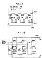
- a three-phase half-wave motor according to a tenth embodiment of this invention will be described with reference to Figs. 33 to 35.
- the primary difference between the motor of this embodiment and that of the above-described ninth embodiment is that the main body of the motor is reduced in size.
- the main body of the motor comprises a rotor 801 having four salient poles 801a to 801d and a rotary shaft 805, and an armature 816 having first- to third-phase magnetic poles 816a to 816c on which first- to third-phase exciting coils 817a to 817c are respectively fitted.
- armature 816 having first- to third-phase magnetic poles 816a to 816c on which first- to third-phase exciting coils 817a to 817c are respectively fitted.
- To the armature are secured detection coils 810a to 810c which constitute a position detection device in cooperation with a circuit (not shown) equivalent to that shown in Fig. 10, 31 or 32 and having three output terminals corresponding, for example, to the terminals 118a to 118c.
- the output terminals of the position detection device are connected to input terminals 804a to 804c of a current supply control circuit shown in Fig. 35, respectively.
- the current supply control circuit has substantially the same arrangement as that shown in Fig. 7 and differs therefrom in that it does not have an element corresponding to the capacitor 19 in Fig. 7.
- the numbering of the elements in Fig. 35 is similar to that in Fig. 7.
- the current supply control circuit carries out a current supply control substantially in the same manner as aforesaid with reference to the various embodiments, in accordance with position detection signals corresponding to the signals 131 to 133 shown in Fig. 12, to thereby control the exciting currents as shown in Fig. 30 similar to Fig. 13.
- the control action is apparent from the description of the third embodiment given with reference to Fig. 13, and accordingly, a description of Fig. 30 is omitted.
- the motor of this embodiment differs from that of the tenth embodiment in that the output torque is largely increased.
- the armature of the motor main body has magnetic poles 816a' to 816c' each having a pair of magnetic pole pieces, and the magnetic pole pieces of each pair are spaced from each other by an electrical angle equivalent to the width of the salient poles (some of them are shown at 801a' to 801d'). Cutouts 803a' to 803c' are formed in the armature 816' each in a position corresponding to an intermediate portion between adjacent magnetic poles.
- the magnetic pole 816b when the magnetic pole 816b, for instance, is excited to act as N pole, then the magnetic flux passing the magnetic pole 816b branches off into two passing the salient poles 801a and 801d, respectively, and a torque produced due to the interaction between the magnetic pole 816c and the salient pole 801d acts as a counter-torque and reduces the output torque.
- the motor of the eleventh embodiment when an electric current is supplied, e.g., to the exciting coil 817b', the magnetic flux passing the magnetic pole 816b' is closed via the salient poles, and accordingly, the magnetic reluctance is small, with the result that the magnetic attractive force acting between a magnetic pole and a salient pole is increased. Since the magnetic reluctance is increased at the regions corresponding to the cutouts 803a' to 803c' of the armature 816', the magnetic flux passing a magnetic pole in no way branches off to the other magnetic poles. According to this arrangement, the output torque is about four times larger, compared to the arrangement of magnetic poles shown in Fig. 34.
- the width between a pair of magnetic pole pieces in each magnetic pole is increased and the number of salient poles is reduced, to thereby ensure a larger space for the exciting coils.
- the main body of the motor according to this embodiment is used, for example, with the detection coils of Fig. 34 and the current supply control circuit of Fig. 35.
- the motor of this embodiment comprises a main body (not shown) corresponding to that of the fourth embodiment, shown in Fig. 14, a position detection device (Fig. 37) corresponding to that shown in Fig. 10, and a current supply control circuit (Fig. 38) corresponding to that shown in Fig. 16.
- detection coils 910a and 910b are spaced from each other by (180 + 90) degrees, and smoothing capacitors for rectification, corresponding to the capacitors 112a and 112b in Fig. 10, are omitted.
- the capacitors are dispensable because the inputs to operational amplifiers 913a and 913b are previously rectified by diodes arranged before the operational amplifiers, and by omitting the capacitors the integration of the circuit is facilitated.
- Inverters 913d and 913e corresponding to the inverters 713d and 713e in Fig. 32 are arranged after the operational amplifier 913a, and similarly, two inverters are arranged after the operational amplifier 913b.
- AND circuits 940a to 940d function similar to the logic circuit 718 in Fig. 32.
- the current supply control circuit of Fig. 38 has a basic arrangement identical to that of the circuit in Fig. 16, but differs therefrom in that the chopper circuit is omitted.
- symbols B" and C" represent current supply control circuits for the exciting coil pairs M' and S', respectively.
- the operation of the motor according to this embodiment is substantially the same as that of the motor of the aforementioned fourth embodiment.
- the operational amplifiers 913a and 913b in Fig. 37 output rectangular-wave signals corresponding respectively to the signals 271 and 272 in Fig. 17.
- the inverter 913d arranged after the operational amplifier 913a and the inverter arranged after the operational amplifier 913b provide rectangular-wave signals corresponding respectively to the signals 273 and 274 in Fig. 17.
- the AND circuits 940a to 940d provide rectangular-wave signals corresponding respectively to the signals 382 to 385 in Fig. 17.
- the signals from the AND circuits each turn to high-level with a period of 360 degrees (illustrated in Fig.
- each high-level signal has a width of 90 degrees.
- an electric current is supplied to corresponding ones of the exciting coil pairs K', L', M' and S', such that the exciting current varies along the curve shown in Fig. 39.
- these high-level signals are generated without interruption, whereby the starting characteristic of the motor is ensured.
- the capacitor 947 is charged up to a level higher than the power supply voltage by the magnetic energy stored in the exciting coil pairs and supplied thereto through the diodes 921a, 921b, etc., whereby the exciting current flowing through the coil pair to which the current supply is interrupted quickly falls and the occurrence of counter-torque is prevented.
- the voltage of the charged capacitor is applied to the coil pair for which the current supply has been started, thereby quickly raising the exciting current and preventing the occurrence of reduced-torque.
- the transistors (e.g., the transistor 20a) serving as switching elements may be replaced by other semiconductor elements.
- the transistors 20a, 20c and 20e alone are turned on and off by the chopper control; alternatively, the transistors 20a and 20b, the transistors 20c and 20d and the transistors 20e and 20f may be turned on and off.
- the position detection signals of individual phases may be produced by conventional means provided in a conventional Y-connection direct current motor and comprising AND circuits. In this case, however, it is likely that an interruption may exist between the position detection signals, for example, between the signals 28a and 29a, causing a disadvantage in the case of a three-phase half-wave motor in that the starting torque cannot be generated.
- the detection coils are arranged in a facing relation to the salient poles of the rotor to obtain the position detection signals
- an aluminum plate having the same shape as the rotor may be provided for synchronous rotation with the rotor and the detection coils may be arranged to be opposed to projections of the aluminum plate.
- magnetic reluctance elements may be arranged in a facing relation to the magnetic poles of a magnet rotor rotatable synchronously with the rotor, so that output changes of the magnetic reluctance elements can be detected as the position detection signals.
- each of the magnetic poles of the armature may be constituted by a pair of magnetic pole teeth having the same width and arranged at equal distances, such that the paired magnetic pole teeth are magnetized to be N and S poles, respectively, to extinguish the leakage flux from one magnetic pole tooth by the other.
- sixteen salient poles may be provided in the rotor 1, whereby the motor can produce two-fold output torque.
- each of the magnetic poles of the armature may be constituted by n pairs of magnetic pole teeth having the same width and arranged at equal distances and the number of the salient poles of the rotor may be increased correspondingly, whereby the output torque can be increased n times.
- a pair of exciting coils have different numbers of winding to eliminate rotational vibration.
- the rotary shaft 5 may be supported by the bearings such that it is deviated to one side (upper right side) of the dashed line 3 in Fig. 1 by about 20 ⁇ m.
- the gap between the magnetic pole 16b and the salient pole 1b is the smallest, while the gap between the magnetic pole 16a and the salient pole 1a and that between the magnetic pole 16c and the salient pole 1d are slightly larger.
- the rotor 1 receives only the force acting in the upper-right direction with respect to the dashed line 3, whereby the rotational vibration is prevented.
- the length of projection of the magnetic poles 16a to 16c may be increased by about 20 ⁇ m, compared to the length of projection of the other magnetic poles, to obtain a smaller gap and thus achieve a similar effect of eliminating the rotational vibration.
- a diode equivalent to the aforesaid reverse current-preventing diode 18 may be inserted at the direct current power supply positive terminal (2a) side of the current supply control circuit (Fig. 4), in which case, the motor of the first embodiment can be operated also by a low-voltage direct current power supply.
- the required number of reverse current-preventing diodes are inserted at the direct current power supply positive terminal side, they may be inserted at the direct current power supply negative terminal side.
- the current supply starting time may be advanced as in the first embodiment, to make the output torque characteristic even.
- a differentiating circuit may be provided at the output terminal of the operational amplifier 240a, followed by a monostable circuit having an output side connected to the base of the transistor 241a, and further, a differentiating circuit and a monostable circuit may be arranged likewise between the operational amplifier 240b and the transistor 241b.
- the differentiating circuit generates a pulse in response to a high-level output of the operational amplifier 240 which is produced when the exciting current flowing through the exciting coil pair K' becomes larger than the preset value corresponding to the reference voltage applied to the terminal 240.
- the monostable circuit In response to the pulse from the differentiating circuit, the monostable circuit produces a high-level output of a predetermined width, which is supplied to the base of the transistor 241c, making the transistor turned off. Thereafter, when the exciting current drops below the preset value, the transistor is again turned on. This operation is repeated to effect a chopper control. Similar chopper control is executed for the other exciting coil pairs.
- the above modification is possible with respect to the third embodiment.
- the logical sum of adjacent ones of the position detection signals in the fourth embodiment is employed as the position detection signal.
- a differential pulse generated in accordance with the rise of one of adjacent signals and that generated in accordance with the fall of the other may be input to the set input terminal and reset input terminal of the flip-flop circuit, so that a signal from the set output terminal of this flip-flop circuit may be used as the position detection signal.
- a series of high-level position detection signals can be continuously generated and the motor can be self-started with reliability. In this arrangement, if the fall of the exciting current is delayed, no counter-torque is caused due to such delay.
- the sixth embodiment uses a current supply control circuit which is equivalent to the current supply control circuit of the fifth embodiment but with the chopper circuit omitted.
- This current supply control circuit can be used in the third and fourth embodiments.
- the chopper circuit described with reference to the seventh embodiment may be provided in the fourth and fifth embodiments.
- the rotor is arranged radially outward of the armature, it may be arranged radially inward of same.
- two detection coils are used as the position detecting elements to reduce the cost and improve the heat resistance.
- a magnetic pole having the shape shown in Fig. 40 may be used to increase the output torque of the motor.
- reluctance motors can produce an output torque proportional to the exciting current and larger than the output torque of magnet direct current motors, even after the excited magnetic poles are magnetically saturated, and this output torque is derived from the leakage flux, as explained with reference to Fig. 28.
- the shape of the magnetic pole 16a, shown in Fig. 40 was contrived taking these properties into account, wherein the width Z between the magnetic-path open ends of the magnetic pole 16a along the rotating direction of the rotor is smaller than the width of the magnetic pole. With this magnetic pole, the magnetic-pole open ends are oversaturated when a certain portion of the exciting coil 17a becomes saturated, and the leakage flux, and thus, the output torque are increased.
Landscapes
- Engineering & Computer Science (AREA)
- Power Engineering (AREA)
- Control Of Electric Motors In General (AREA)
Abstract
Claims (24)
- Un moteur à réluctance (par exemple Fig. 1) comprenant un rotor (1) présentant un ensemble de pôles saillants (1a à 1h), un induit (16) présentant un ensemble de pôles magnétiques (16a à 16f) sur lequel des bobines d'excitation (17a à 17f) sont respectivement montées, un circuit de commande d'alimentation de courant (par exemple Fig. 7) relié à une alimentation d'énergie électrique à courant continu pour fournir de manière séquentielle un courant électrique aux bobines d'excitation (17a à 17f), et un dispositif de détection de position (par exemple Fig. 3) pour délivrer de manière séquentielle des signaux de détection de position dont le nombre correspond à celui dudit ensemble de bobines d'excitation (17a à 17f), en accord avec une position de rotation du rotor (1), de manière ainsi à déterminer l'alimentation séquentielle de courant aux bobines d'excitation (17a à 17f) ;
le moteur étant caractérisé par :
des moyens de circuit qui, lorsque l'alimentation de courant vers chacune des bobines d'excitation (17a à 17f) est interrompue, amènent l'énergie magnétique stockée dans la bobine d'excitation pour laquelle l'alimentation de courant est interrompue, à passer de là dans un condensateur (19), les moyens de circuit comprenant en outre une diode (18) prévue entre lesdites bobines d'excitation (17a à 17f) et ladite alimentation en énergie électrique à courant continu pour empêcher à l'énergie magnétique de revenir vers ladite alimentation d'énergie électrique à courant continu, cette énergie magnétique passant alors depuis le condensateur (19) dans une autre bobine d'excitation pour laquelle l'alimentation de courant est amenée à démarrer au moment de ladite interruption de l'alimentation de courant, de manière ainsi à éteindre rapidement l'énergie magnétique stockée et élever rapidement un courant d'excitation traversant ladite autre bobine d'excitation. - Un moteur à réluctance selon la revendication 1, dans lequel ledit dispositif de détection de position (par exemple Fig. 3) est prévu pour délivrer de manière séquentielle un premier groupe de signaux de détection de position et un second groupe de signaux de détection de position présentant des différences de phase prédéterminées par rapport aux signaux de détection de position du premier groupe, respectivement en accord avec une position de rotation du rotor (1), et
le circuit de commande d'alimentation de courant (par exemple Fig. 7) relié à ladite alimentation d'énergie électrique à courant continu est prévu pour appliquer de manière séquentielle un courant électrique à des bobines d'excitation formant un premier groupe en accord avec les signaux de détection de position du premier groupe, et appliquer de manière séquentielle un courant électrique à des bobines d'excitation formant un second groupe en accord avec les signaux de détection de position du second groupe. - Un moteur à réluctance selon la revendication 1 ou 2, qui comprend un circuit hacheur (par exemple Fig. 11, 140a, 141a) pour interrompre l'alimentation de courant vers une bobine d'excitation lorsque le courant d'excitation circulant à travers cette bobine d'excitation devient plus grand qu'une valeur limite supérieure, et redémarrer l'alimentation en courant lorsque ledit courant d'excitation devient plus petit qu'une valeur limite inférieure.
- Un moteur à réluctance selon la revendication 1, 2 ou 3, dans lequel ledit dispositif de détection de position (par exemple Fig. 3) produit les signaux de détection de position de manière continue et successive sans superposer les signaux de détection de position l'un sur l'autre dans le temps, lesdits signaux de détection de position présentant chacun une largeur correspondant à un angle électrique déterminé à l'avance.
- Un moteur à réluctance selon une revendication précédente quelconque, dans lequel ledit dispositif de détection de position (par exemple Fig. 3) comprend un ensemble d'éléments de détection de position (10a, 10b, 10c) fixés audit induit (16) et écartés les uns des autres d'un angle électrique déterminé à l'avance afin de produire lesdits signaux de détection de position.
- Un moteur à réluctance selon la revendication 5, dans lequel lesdits éléments de détection de position (10a, 10b, 10c) sont chacun fixés dans une position telle que ledit dispositif de de détection de position produit un signal de détection de position capable d'effectuer l'alimentation de courant vers la bobine d'excitation dans un intervalle de formation de couple maximum.
- Un moteur à réluctance selon une revendication précédente quelconque, dans lequel ledit circuit de commande d'alimentation de courant comprend des transistors (20) reliés respectivement auxdites bobines d'excitation (17a à 17f) et mises à l'état passant et non passant en accord avec lesdits signaux de détection de position.
- Un moteur à réluctance selon la revendication 1, qui est un moteur à réluctance triphasé simple alternance dans lequel :le dispositif de détection de position (Fig. 3) présente trois éléments de détection de position (10a, 10b, 10c) écartés les uns des autres d'un angle électrique de 120 degrés, afin de produire des signaux de détection de position de première à troisième phases en accord avec les positions de rotation des pôles saillants (1a à 1h) du rotor (1) ;des éléments de commutation (20) sont: reliés respectivement aux deux extrémités de bobines d'excitation de première à troisième phases et forment chacun des moyens de liaison en coopération avec la bobine d'excitation associée ;des diodes sont reliées en inverse aux éléments de commutation associés ;le circuit de commande d'alimentation de courant (Fig. 7) est sensible à chacun des signaux de détection de position pour mettre à l'état passant un élément de commutation (20) correspondant pendant une période correspondant à une largeur du signal de détection de position, de manière ainsi à appliquer un courant électrique à une bobine d'excitation correspondante de première à troisième phases ;un circuit hacheur est prévu pour maintenir le courant électrique circulant à travers les bobines d'excitation individuelles à une valeur réglée au préalable et correspondant à une tension de référence ;l'alimentation en énergie électrique à courant continu est prévue pour fournir auxdits circuits de commande d'alimentation de courant une tension suffisamment grande pour supprimer une réduction de couple et un couple antagoniste provoqué respectivement au démarrage et à une interruption de l'alimentation de courant vers les bobines d'excitation, etlesdits éléments de détection de position (10a, 10b, 10c) sont fixés au stator (16) et placés chacun dans une position telle que ledit dispositif de détection de position forme un signal de détection de position capable de produire un couple de sortie maximum et régulier du moteur en fournissant un courant électrique auxdites bobines d'excitation de première à troisième phases.
- Un moteur à réluctance triphasé simple alternance selon la revendication 8, dans lequel, lorsqu'un des signaux de détection de position produits de manière successive est éteint et qu'un autre signal de détection de position est produit, ladite diode empêchant le courant inverse (par exemple 19) empêche que l'énergie magnétique stockée dans une bobine d'excitation concernée par ce signal de détection de position de retourner vers ladite alimentation d'énergie électrique à courant continu, et ladite énergie magnétique est rapidement convertie en une énergie magnétique stockée dans une bobine d'excitation concernée par ledit autre signal de détection de position, de manière ainsi à diminuer la réduction de couple et le couple antagoniste.
- Un moteur à réluctance triphasé simple alternance selon la revendication 8 ou 9, dans lequel ledit rotor (1) présente huit pôles saillants de même longueur et montés à des distances égales, et ledit stator (16) présente six pôles magnétiques de même largeur que lesdits pôles saillants et montés à des distances égales avec un faible entrefer défini par rapport auxdits pôles saillants.
- Un moteur à réluctance triphasé simple alternance selon la revendication 9 ou 10, dans lequel lesdites bobines d'excitation (17a à 17f) comprennent trois paires de bobines d'excitation, chaque paire comportant deux bobines d'excitation reliées l'une à l'autre et montées sur deux pôles magnétiques prévus symétriquement autour d'un arbre rotatif dudit rotor (1), une bobine d'excitation de chaque paire présente un nombre d'enroulements supérieur à celui de l'autre bobine d'excitation de la même paire d'un nombre déterminé à l'avance, de telle manière qu'une force d'attraction magnétique agissant entre le pôle magnétique et le pôle saillant dans une direction radiale du rotor est seulement variable dans une plage angulaire machine de 180 degrés.
- Un moteur à réluctance triphasé simple alternance selon la revendication 9, 10 ou 11, dans lequel les distances des entrefers entre les pôles magnétiques et les pôles saillants sont réglés de telle manière qu'une faible différence existe entre une force d'attraction magnétique produite entre les pôles saillants et ceux des pôles magnétiques prévus le long d'une première demi-circonférence dudit stator et agissant dans une direction radiale du rotor, et une force d'attraction magnétique produite entre les pôles saillants et ceux des pôles magnétiques prévus le long d'une autre demi-circonférence dudit stator et agissant dans la direction radiale du rotor.
- Un moteur à réluctance selon la revendication 1, qui est un moteur à réluctance biphasé (par exemple Fig. 14) dans lequel :le dispositif de détection de position présente deux éléments de détection de position (208a, 208b) fixés à l'induit et espacés l'un de l'autre d'un angle électrique de 90 degrés, afin de produire de premier à quatrième signaux de détection de position qui sont continus mais non superposés l'un sur l'autre dans le temps et qui présentent chacun une largeur équivalente à un angle électrique de 90 degrés, en accord avec des positions de rotation des pôles saillants du rotor ;de première et seconde bobines d'excitation (217) forment une paire de bobines d'excitation de première phase ;de troisième et quatrième bobines d'excitation forment une paire de bobines d'excitation de seconde phase ;des transistors (220) sont reliés respectivement aux deux extrémités desdites première à quatrième bobines d'excitation ;le circuit de commande d'alimentation de courant est prévu pour mettre cycliquement à l'état passant lesdits transistors (220) en accord avec les premier à quatrième signaux de détection de position, afin d'appliquer un courant électrique aux bobines d'excitation correspondantes parmi les première à quatrième bobines d'excitation à partir de l'alimentation d'énergie électrique à courant continu et produire ainsi un couple unidirectionnel de sortie du moteur ;des diodes (221) sont reliées individuellement en sens inverse et en parallèle à des moyens de liaison composés d'une première desdites bobines d'excitation et d'un desdits transistors associé ;une diode empêchant le courant inverse (249a) est reliée entre ledit circuit de commande d'alimentation de courant et ladite alimentation d'énergie électrique à courant continu dans le sens direct par rapport à ladite alimentation d'énergie électrique à courant continu ;un condensateur (248a) est relié entre ledit circuit de commande d'alimentation de courant et ladite alimentation d'énergie électrique à courant continu en parallèle à ladite alimentation d'énergie électrique à courant continu ;lesdits éléments de détection de position (208a, 208b) sont chacun montés dans une position telle que ledit dispositif de détection de position produit un signal de détection de position capable de faire qu'un intervalle d'alimentation en courant de chaque bobine d'excitation (217) coïncide avec un intervalle de production de couple maximum ; etlesdits moyens de circuit, lorsqu'un premier signal de détection de position est éteint, coopèrent avec ladite diode empêchant le courant inverse (249a) pour empêcher que l'énergie magnétique, stockée dans une bobine d'excitation (217) concernée par ledit premier signal de détection de position, retourne vers l'alimentation d'énergie électrique à courant continu par l'intermédiaire de la diode reliée en inverse (221), et amènent l'énergie magnétique stockée à passer dans une autre bobine d'excitation (217) concernée par un autre signal de détection de position qui est produit lorsque ledit premier signal de détection de position est éteint, en éliminant ainsi un couple antagoniste provoqué par la décharge de l'énergie magnétique stockée et une réduction de couple provoquée par un retard de la montée d'un courant d'excitation circulant à travers ladite autre bobine d'excitation (217), afin de permettre le fonctionnement à grande vitesse du moteur.
- Un moteur à réluctance biphasée selon la revendication 13, qui comprend une diode (349) reliée dans le sens direct entre ledit circuit de commande d'alimentation de courant et ladite alimentation d'énergie électrique à courant continu, un élément de commutation à semi-conducteur (341) inséré entre ledit circuit de commande d'alimentation de courant et ladite alimentation d'énergie électrique à courant continu, et un circuit hacheur (350) pour mettre à l'état passant et non passant ledit élément de commutation à semi-conducteur (341) afin de commander ainsi le courant d'excitation circulant à travers chacune des bobines d'excitation (217) pour tomber dans une plage déterminée à l'avance.
- Un moteur à réluctance selon la revendication 1, qui est un moteur biphasé à réluctance dans lequel :le dispositif de détection de position présente deux éléments de détection de position (208a, 208b) pour produire un premier groupe de signaux de détection de position qui sont continus mais non superposés l'un sur l'autre dans le temps et qui présentent chacun une largeur équivalant à un angle électrique de 180 degrés, et un second groupe de signaux de détection de position qui sont continus mais non superposés l'un sur l'autre dans le temps et qui présentent chacun une largeur équivalant à un angle électrique de 90 degrés, en accord avec des positions de rotation des pôles saillants (201) du rotor ;une paire de bobines d'excitation de première phase est composée de première et seconde bobines d'excitation (K'L') ;une paire de bobines d'excitation de seconde phase est composée de troisième et quatrième bobines d'excitation (M'S') ;des transistors (220) sont reliés respectivement aux deux extrémités desdites première à quatrième bobines d'excitation (K'L'M'S') ;le circuit de commande d'alimentation de courant est prévu pour mettre alternativement à l'état passant ceux des transistors (220) associés auxdites première et seconde bobines d'excitation (K'L') en accord avec le premier groupe de signaux de détection de position, et mettre alternativement à l'état passant ceux des transistors (220) associés auxdites troisième et quatrième bobines d'excitation (M'S') en accord avec le second groupe de signaux de détection de position, afin de fournir un courant électrique aux bobines correspondantes parmi les première à quatrième bobines d'excitation à partir de l'alimentation d'énergie électrique à courant continu et produire ainsi un couple unidirectionnel de sortie du moteur ;des diodes (221) sont reliées individuellement en sens inverse et en parallèle à des moyens de liaison composés d'une desdites bobines d'excitation et d'un desdits transistors (220) associé ;des diodes empêchant le courant inverse (249) sont reliées entre ledit circuit de commande d'alimentation de courant et ladite alimentation d'énergie électrique à courant continu dans le sens direct par rapport à lacite alimentation d'énergie électrique à courant continu ;des condensateurs (247) sont reliés entre ledit circuit de commande d'alimentation en courant et ladite alimentation d'énergie électrique à courant continu en parallèle à ladite alimentation d'énergie électrique à courant continu ;lesdits éléments de détection de position (208a, 208b) sont chacun fixés dans une position telle que ledit dispositif de détection de position produit un signal de détection de position capable de démarrer une alimentation de courant vers chacune des bobines d'excitation au niveau d'une position de rotation du rotor qui est antérieure à une position de rotation où un pôle saillant arbitraire (201) vient dans chaque pôle magnétique par un angle électrique déterminé à l'avance ; etlesdits moyens de circuit, lorsqu'un premier signal de détection de position est éteint, coopèrent avec ladite diode empêchant le courant inverse (249) pour empêcher que l'énergie magnétique, stockée dans une bobine d'excitation concernée par ledit premier signal de détection de position, retourne vers l'alimentation d'énergie électrique à courant continu à travers la diode reliée en inverse (221), et amènent l'énergie magnétique stockée à passer dans une autre bobine d'excitation concernée par un autre signal de détection de position qui est produit lorsque ledit premier signal de détection de position est éteint, en éliminant ainsi un couple antagoniste provoqué par la décharge de l'énergie magnétique stockée et une réduction du couple provoquée par un retard de la montée du courant d'excitation circulant à travers ladite autre bobine d'excitation, afin de permettre un fonctionnement à vitesse élevée du moteur.
- Un moteur biphasé à réluctance selon la revendication 15, qui comprend des éléments de commutation à semi-conducteurs (241) reliés entre ladite alimentation d'énergie électrique à courant continu et des diodes respectives parmi lesdites diodes empêchant le courant inverse (249), et un circuit hacheur (240) pour mettre à l'état passant et à l'état non passant lesdits éléments de commutation à semi-conducteurs (241) afin de commander le courant d'excitation circulant à travers chacune des bobines d'excitation pour tomber dans une plage déterminée à l'avance.
- Un moteur à réluctance selon la revendication 1, qui est un moteur triphasé à réluctance dans lequel :le dispositif de détection de position présente trois éléments de détection de position (110) fixés à l'induit et écartés les uns des autres d'un angle électrique de 120 degrés, afin de produire un premier groupe de signaux de détection de position qui sont continus mais non superposés l'un sur l'autre dans le temps, et un second groupe de signaux de détection de position qui sont continus mais non superposés l'un sur l'autre dans le temps et qui présentent chacun une différence de phase équivalant à un angle électrique de 60 degrés par rapport aux signaux de détection de position correspondant du premier groupe, en accord avec des positions de rotation des pôles saillants du rotor ;une paire de bobines d'excitation de première phase est composée de première et seconde bobines d'excitation (117a, 117b) ;une paire de bobines d'excitation de seconde phase est composée de troisième et quatrième bobines d'excitation (117c, 117d) ;une paire de bobines d'excitation de troisième phase est composée de cinquième et sixième bobines d'excitation (117e, 117f) ;des transistors (120) sont reliés respectivement aux deux extrémités desdites première à sixième bobines d'excitation (117) ;le circuit de commande d'alimentation de courant est prévu pour mettre cycliquement à l'état passant ceux des transistors (120) associés auxdites première, troisième et cinquième bobines d'excitation en accord avec le premier groupe de signaux de détection de position, et mettre cycliquement à l'état passant ceux des transistors (120) associés auxdites seconde, quatrième et sixième bobines d'excitation en accord avec le second groupe de signaux de détection de position, afin d'appliquer un courant électrique aux bobines correspondantes parmi les première à sixième bobines d'excitation (117) à partir de l'alimentation d'énergie électrique à courant continu et produire ainsi un couple unidirectionnel de sortie du moteur ;des diodes (121) sont reliées individuellement en sens inverse et en parallèle à des moyens de liaison composés d'une desdites bobines d'excitation (117) et d'un desdits transistors (120) associé ;des diodes empêchant le courant inverse (149) sont reliées entre ledit circuit de commande d'alimentation de courant et ladite alimentation d'énergie électrique à courant continu dans le sens direct par rapport à ladite alimentation d'énergie électrique à courant continu ;des condensateurs (147, 148) sont reliés entre ledit circuit de commande d'alimentation de courant et ladite alimentation d'énergie électrique à courant continu en parallèle à ladite alimentation d'énergie électrique à courant continu ;lesdits éléments de détection de position (110) sont chacun fixés à l'induit dans une position telle que ledit dispositif de détection de position produit un signal de détection de position capable de faire qu'un intervalle d'alimentation en courant de chaque bobine d'excitation (117) coïncide avec un intervalle de production de couple maximum ; etlesdits moyens de circuit, lorsqu'un premier signal de détection de position est éteint. coopèrent avec la diode empêchant le courant inverse (149) afin d'empêcher que l'énergie magnétique, stockée dans une bobine d'excitation (117) concernée par ledit premier signal de détection de position, retourne vers l'alimentation d'énergie électrique à courant continu à travers la diode reliée en inverse (121), etamènent l'énergie magnétique stockée à passer dans une autre bobine d'excitation (117) concernée par un autre signal de détection de position qui est produit lorsque ledit premier signal de détection de position est éteint, en éliminant ainsi un couple antagoniste provoqué par la décharge de l'énergie magnétique stockée et une réduction de couple provoquée par un retard de la montée d'un courant d'excitation circulant à travers ladite autre bobine d'excitation (117), afin de permettre un fonctionnement à vitesse élevée du moteur.
- Un moteur à réluctance triphasé selon la revendication 17, qui comprend des éléments de commutation à semi-conducteurs (141) reliés entre ladite alimentation d'énergie électrique à courant continu et les diodes respectives empêchant le courant inverse (149), ainsi. qu'un circuit hacheur (140) pour mettre à l'état passant et. non passant lesdits éléments de commutation à semi-conducteurs (141) afin de commander le courant d'excitation circulant à travers chacune des bobines d'excitation (117) afin de tomber dans une plage déterminée à l'avance.
- Un moteur à réluctance selon la revendication 1, qui est un moteur à réluctance triphasé dans lequel :le dispositif de détection de position présente deux éléments de détection de position (608a, 608b) écartés l'un de l'autre d'un angle électrique de (60+120n) degrés (n est un nombre entier positif), et une partie de détection (614) comprenant n séries de trois éléments de détection (614a, b, c) prévus sur un élément de détection de position tournant pouvant tourner de manière synchrone avec le rotor et présentant chacun une largeur équivalant à un angle électrique de 120 degrés, lesdits éléments de détection de position (608a, 608b) et lesdits organes de détection (614a, b, c) étant différents en degrés d'effets d'interaction physique, ledit dispositif de détection de position produisant un premier groupe de signaux de détection de position qui sont continus mais non superposés l'un sur l'autre dans le temps et qui présentent chacun une largeur équivalant à un angle électrique de 120 degrés, et un second groupe de signaux de détection de position qui sont continus mais non superposés l'un sur l'autre dans le temps et qui présentent chacun une différence de phase équivalant à un angle électrique de 60 degrés par rapport aux signaux correspondants de détection de position du premier groupe, en accord avec une position de rotation de l'organe tournant ;une paire de bobines d'excitation de première phase est composée de première et seconde bobines d'excitation (117a, 117b) ;une paire de bobines d'excitation de seconde phase est composée de troisième et quatrième bobines d'excitation (117c, 117d) ;une paire de bobines d'excitation de troisième phase est composée de cinquième et sixième bobines d'excitation (117e, 117f) ;des transistors (120) sont reliés respectivement aux deux extrémités desdites première à sixième bobines d'excitation ;le circuit de commande d'alimentation de courant est prévu pour mettre cycliquement à l'état passant les transistors (120) associés auxdites première, troisième et cinquième bobines d'excitation en accord avec les signaux de détection de position du premier groupe, et mettre cycliquement à l'état passant les transistors (120) associés auxdites seconde, quatrième et sixième bobines d'excitation en accord avec les signaux de détection de position du second groupe, afin d'appliquer un courant électrique aux bobines d'excitation correspondantes parmi les première à sixième bobines d'excitation (117) à partir de l'alimentation d'énergie électrique à courant continu et produire ainsi un couple unidirectionnel de sortie du moteur ;des diodes (149) sont reliées dans le sens direct entre ladite alimentation d'énergie électrique à courant continu et ledit circuit de commande d'alimentation de courant ;des condensateurs de faible capacité (147, 148) sont reliés en parallèle au côté d'alimentation d'énergie électrique à courant continu dudit circuit de commande d'alimentation en courant ;des éléments de commutation à semi-conducteurs (141) sont reliés entre l'alimentation d'énergie électrique à courant continu et les diodes (149) respectives ; etun circuit hacheur (140) est prévu pour mettre à l'état passant et non passant lesdits éléments de commutation à semi-conducteurs (141) pour commander le courant d'excitation circulant à travers chacune des bobines d'excitation (117) afin de tomber dans une plage déterminée à l'avance, lesdits éléments de détection de position (608a, 608b) étant chacun montés à une position telle que ledit dispositif de détection de position produit un signal de détection de position capable de faire qu'un intervalle d'alimentation de courant de chaque bobine d'excitation (117) coïncide avec un intervalle de production de couple maximum.
- Un moteur à réluctance triphasé selon la revendication 19, dans lequel ledit organe tournant a la forme d'une coupelle plane (602) (Fig. 22) et présente une partie centrale fixée à une extrémité supérieure d'un arbre tournant (604), ledit rotor (601) présentant sept pôles saillants fixés sur une surface périphérique interne de l'organe tournant à des distances égales, et ledit induit (616) présentant des pôles magnétiques sur lesquels lesdites première à sixième bobines d'excitation (117) sont respectivement montées et qui sont prévues à des distances égales.
- Un moteur à réluctance triphasé selon la revendication 19 ou 20, qui comprend un détecteur de vitesse (656) pour produire un signal représentant une vitesse de rotation dudit organe tournant, ledit circuit hacher (140) commandant le courant d'excitation circulant à travers chacune des bobines d'excitation (117) en accord avec une sortie dudit détecteur de vitesse (656) et une charge appliquée sur le moteur, de manière ainsi à effectuer un fonctionnement à vitesse constante du moteur.
- Un moteur à réluctance selon la revendication 1, qui est un moteur à réluctance biphasée dans lequel :le dispositif de détection de position présente deux éléments de détection de position afin de produire de premier à quatrième signaux de détection de position qui sont continus mais non superposés l'un sur l'autre dans le temps et qui présentent chacun une largeur équivalant à un angle électrique de 90 degrés, en accord avec les positions de rotation des pôles saillants du rotor ;de première et seconde bobines d'excitation forment une paire de bobines d'excitation de première phase (K'L') ;de troisième et quatrième bobines d'excitation forment une paire de bobines d'excitation de seconde phase (M'S') ;des transistors (420) sont respectivement reliés aux deux extrémités desdites première à quatrième bobines d'excitation ;le circuit de commande d'alimentation de courant est prévu pour mettre à l'état passant les transistors (420) reliés respectivement auxdites première, troisième, seconde et quatrième bobines d'excitation en accord avec les premier à quatrième signaux de détection de position ;une diode empêchant le courant inverse (449) est reliée dans le sens direct à ladite alimentation d'énergie électrique à courant continu pour permettre à un courant électrique d'être appliqué aux bobines d'excitation individuelles à partir de l'alimentation d'énergie électrique à courant continu ;lesdits éléments de détection de position sont fixés à l'induit et sont chacun montés dans une position telle que ledit dispositif de détection de position produit un signal de détection de position capable de faire qu'un intervalle d'alimentation de courant de chaque bobine d'excitation coïncide avec un intervalle de production de couple maximum ; etlesdits moyens de circuit, lorsqu'un premier signal de détection de position est éteint, coopèrent avec la diode empêchant le courant inverse (449) afin d'empêcher à l'énergie magnétique, stockée dans une bobine d'excitation concernée par ledit premier signal de détection de position, de retourner vers l'alimentation d'énergie électrique à courant continu, et amènent l'énergie magnétique stockée à passer dans une autre bobine d'excitation concernée par un autre signal de détection de position qui est produit lorsque ledit premier signal de détection de position est éteint, de manière à accélérer une montée et une chute du courant d'excitation circulant à travers les bobines d'excitation individuelles, en supprimant ainsi un couple antagoniste et une réduction de couple, et en permettant l'utilisation d'une alimentation d'énergie électrique basse tension en tant qu'alimentation d'énergie électrique à courant continu.
- Un moteur à réluctance selon la revendication 1, qui est un moteur à réluctance triphasé dans lequel :le dispositif de détection de position présente trois éléments de détection de position afin de produire de premier à troisième signaux de détection de position qui sont continus mais non superposés l'un sur l'autre dans le temps et qui présentent chacun une largeur équivalant à un angle électrique de 120 degrés, et de quatrième à sixième signaux de détection de position qui sont continus mais non superposés l'un sur l'autre dans le temps et qui présentent chacun une largeur équivalant à un angle électrique de 120 degrés et une différence de phase équivalant à un angle électrique de 60 degrés par rapport à un signal correspondant parmi lesdits premier à troisième signaux de détection de position, en accord avec des positions de rotation des pôles saillants du rotor ;des transistors (720) sont reliés respectivement aux deux extrémités desdites première à sixième bobines d'excitation (717a à 717f) ;le circuit de commande d'alimentation de courant est prévu pour mettre à l'état passant les transistors (720) associés respectivement auxdites première, troisième, cinquième, seconde, quatrième et sixième bobines d'excitation (717) en accord avec les premier à sixième signaux de détection de position ;des diodes empêchant le courant inverse (749) sont reliées entre ladite alimentation d'énergie électrique à courant continu et ledit circuit de commande d'alimentation de courant dans le sens direct par rapport à l'alimentation d'énergie électrique à courant continu, afin de permettre à l'énergie électrique d'être appliquée au circuit de commande d'alimentation de courant à partir de l'alimentation d'énergie électrique à courant continu ;lesdits éléments de détection de position sont fixés à l'induit et sont chacun montés dans une position telle que ledit dispositif de détection de position produit un signal de détection de position capable de faire qu'un intervalle d'alimentation de courant de chaque bobine (717) coïncide avec un intervalle de production de couple maximum ; etlesdits moyens de circuit, lorsqu'un premier signal de détection de position est éteint, coopèrent avec la diode empêchant le courant inverse (749) afin d'empêcher que l'énergie électrique, stockée dans une bobine d'excitation (717) concernée par ledit premier signal de détection de position, retourne vers l'alimentation d'énergie électrique à courant continu, et amènent l'énergie magnétique stockée à passer dans une autre bobine d'excitation (717) concernée par un autre signal de détection de position qui est produit lorsque ledit premier signal de détection de position est éteint, afin d'accélérer une montée et une chute du courant d'excitation circulant à travers les bobines d'excitation individuelles (717), en supprimant ainsi un couple antagoniste et une réduction de couple, et en permettant l'utilisation d'une alimentation d'énergie électrique basse tension en tant qu'alimentation d'énergie électrique à courant continu.
- Un moteur à réluctance triphasé selon la revendication 1, dans lequel :le dispositif de détection de position présente trois éléments de détection de position (810), pour produire de premier à troisième signaux de détection de position qui sont continus mais non superposés l'un sur l'autre dans le temps et qui présentent chacun une largeur équivalant à un angle électrique de 120 degrés, en accord avec des positions de rotation des pôles saillants du rotor ;le circuit de commande d'alimentation de courant est prévu pour mettre à l'état passant des transistors (820) reliés respectivement aux deux extrémités de première à troisième bobines d'excitation (817), en accord avec les premier à troisième signaux de détection de position ;une diode empêchant le courant inverse (849) est reliée entre ladite alimentation d'énergie électrique à courant continu et ledit circuit de commande d'alimentation de courant dans le sens direct par rapport à l'alimentation d'énergie électrique à courant continu, afin de permettre à l'énergie électrique d'être appliquée au circuit de commande d'alimentation de courant à partir de l'alimentation d'énergie électrique à courant continu ;lesdits éléments de détection de position sont fixés à l'induit et sont chacun montés dans une position telle que ledit dispositif de détection de position produit un signal de détection de position capable de faire qu'un intervalle d'alimentation de courant de chaque bobine d'excitation coïncide avec un intervalle de production de couple maximum ; etlesdits moyens de circuit; lorsqu'un premier signal de détection de position est éteint; coopèrent avec la diode empêchant le courant inverse (849) afin d'empêcher à l'énergie magnétique, stockée dans une bobine d'excitation (817) concernée par ledit signal de détection deposition, de retourner vers l'alimentation d'énergie électrique à courant continu, et amènent l'énergie magnétique stockée à passer dans une autre bobine d'excitation (817) concernée par un autre signal de détection de position qui est produit lorsque ledit premier signal de détection de position est éteint, afin d'accélérer une montée et une chute du courant d'excitation circulant à travers les bobines d'excitation individuelles (817), en supprimant ainsi un couple antagoniste et une réduction de couple, et en permettant l'utilisation d'une alimentation d'énergie électrique basse tension en tant qu'alimentation d'énergie électrique à courant continu.
Applications Claiming Priority (7)
| Application Number | Priority Date | Filing Date | Title |
|---|---|---|---|
| JP63251855A JPH02101988A (ja) | 1988-10-07 | 1988-10-07 | 3相リラクタンス型電動機 |
| JP251855/88 | 1988-10-07 | ||
| JP63266114A JPH02114884A (ja) | 1988-10-24 | 1988-10-24 | 低電圧で駆動されるリラクタンス型電動機 |
| JP266114/88 | 1988-10-24 | ||
| JP1124406A JPH02307391A (ja) | 1989-05-19 | 1989-05-19 | 3相片波リラクタンス電動機 |
| JP124406/89 | 1989-05-19 | ||
| PCT/JP1989/001033 WO1990004283A1 (fr) | 1988-10-07 | 1989-10-06 | Moteur a reluctance |
Publications (3)
| Publication Number | Publication Date |
|---|---|
| EP0422226A1 EP0422226A1 (fr) | 1991-04-17 |
| EP0422226A4 EP0422226A4 (en) | 1992-06-03 |
| EP0422226B1 true EP0422226B1 (fr) | 1996-05-15 |
Family
ID=27314925
Family Applications (1)
| Application Number | Title | Priority Date | Filing Date |
|---|---|---|---|
| EP89911086A Expired - Lifetime EP0422226B1 (fr) | 1988-10-07 | 1989-10-06 | Moteur a reluctance |
Country Status (3)
| Country | Link |
|---|---|
| EP (1) | EP0422226B1 (fr) |
| DE (1) | DE68926503T2 (fr) |
| WO (1) | WO1990004283A1 (fr) |
Families Citing this family (8)
| Publication number | Priority date | Publication date | Assignee | Title |
|---|---|---|---|---|
| JPH0646593A (ja) * | 1991-02-12 | 1994-02-18 | Secoh Giken Inc | 高速リラクタンス型電動機 |
| WO1992016046A1 (fr) * | 1991-03-07 | 1992-09-17 | Kabushikigaisya Sekogiken | Moteur a grande vitesse |
| JPH07236296A (ja) * | 1994-02-22 | 1995-09-05 | Secoh Giken Inc | 1個の位置検知素子により3相の位置検知信号を得る装置 |
| US6262510B1 (en) | 1994-09-22 | 2001-07-17 | Iancu Lungu | Electronically switched reluctance motor |
| WO1997018617A1 (fr) * | 1995-11-15 | 1997-05-22 | Palmer, Charles, L. | Procede et appareil permettant d'accroitre le rendement d'un moteur a aimant permanent |
| US5661381A (en) * | 1996-02-15 | 1997-08-26 | Dana Corporation | Apparatus for external inductance sensing for variable-reluctance motor commutation |
| US11724098B2 (en) | 2020-01-30 | 2023-08-15 | Terumo Cardiovascular Systems Corporation | Stepper motor drive systems and tubing occluder system |
| CN111371143B (zh) * | 2020-03-24 | 2022-05-27 | 北京经纬恒润科技股份有限公司 | 一种充放电系统 |
Citations (2)
| Publication number | Priority date | Publication date | Assignee | Title |
|---|---|---|---|---|
| US4707630A (en) * | 1985-01-14 | 1987-11-17 | Hitachi, Ltd. | Magnetic cover member for magnetic poles of DC motor |
| WO1988002952A1 (fr) * | 1986-10-10 | 1988-04-21 | Ems Electronic Motor Systems Ab | Circuit d'excitation d'un moteur |
Family Cites Families (4)
| Publication number | Priority date | Publication date | Assignee | Title |
|---|---|---|---|---|
| JPS5418018A (en) * | 1977-07-11 | 1979-02-09 | Ricoh Co Ltd | Pulse motor drive circuit |
| US4164696A (en) * | 1977-08-10 | 1979-08-14 | Teletype Corporation | Stepping motor excitation |
| JPS54102508A (en) * | 1978-01-31 | 1979-08-13 | Nippon Pulsmotor Co Ltd | Coil current controlling pulse motor drive gear |
| JPS63220791A (ja) * | 1987-03-09 | 1988-09-14 | Secoh Giken Inc | 高速電動機 |
-
1989
- 1989-10-06 WO PCT/JP1989/001033 patent/WO1990004283A1/fr active IP Right Grant
- 1989-10-06 DE DE68926503T patent/DE68926503T2/de not_active Expired - Fee Related
- 1989-10-06 EP EP89911086A patent/EP0422226B1/fr not_active Expired - Lifetime
Patent Citations (2)
| Publication number | Priority date | Publication date | Assignee | Title |
|---|---|---|---|---|
| US4707630A (en) * | 1985-01-14 | 1987-11-17 | Hitachi, Ltd. | Magnetic cover member for magnetic poles of DC motor |
| WO1988002952A1 (fr) * | 1986-10-10 | 1988-04-21 | Ems Electronic Motor Systems Ab | Circuit d'excitation d'un moteur |
Non-Patent Citations (1)
| Title |
|---|
| US-A4707630 * |
Also Published As
| Publication number | Publication date |
|---|---|
| WO1990004283A1 (fr) | 1990-04-19 |
| EP0422226A4 (en) | 1992-06-03 |
| EP0422226A1 (fr) | 1991-04-17 |
| DE68926503T2 (de) | 1996-11-14 |
| DE68926503D1 (de) | 1996-06-20 |
Similar Documents
| Publication | Publication Date | Title |
|---|---|---|
| US5260635A (en) | Reluctance motor | |
| US5929590A (en) | Method and apparatus for implementing sensorless control of a switched reluctance machine | |
| US4746844A (en) | Control and operation of brushless continuous torque toroid motor | |
| US6014003A (en) | Method and apparatus for controlling a switched reluctance machine | |
| US4359674A (en) | Control system for a DC motor | |
| US5811905A (en) | Doubly-fed switched reluctance machine | |
| US4961038A (en) | Torque estimator for switched reluctance machines | |
| US5231338A (en) | Controlling a multiphase brushless motor without position sensors for the rotor, using a system of digital filtering | |
| EP0436742B1 (fr) | Moteur a reluctance | |
| EP1441435B1 (fr) | Générateur de réluctance variable | |
| EP0444198B1 (fr) | Moteur a reluctance | |
| EP1265349B1 (fr) | Commande d'une machine à réluctance commutée | |
| EP0577843B1 (fr) | Moteur a reluctance a haute vitesse | |
| EP0422226B1 (fr) | Moteur a reluctance | |
| US6759826B2 (en) | Control strategy for switched reluctance drive systems | |
| EP0785614A1 (fr) | Moteur a reluctance polyphase | |
| JPS644439B2 (fr) | ||
| JP2000166292A (ja) | スイッチ式リラクタンスモータ及びその駆動回路 | |
| EP0387358B1 (fr) | Moteur a courant continu | |
| JPH0534916B2 (fr) | ||
| JPH1094286A (ja) | 動力発生装置 | |
| US5729112A (en) | Phase current sensing in a bifilar-wound switched reluctance motor drive topology | |
| JP2745411B2 (ja) | 高速電動機 | |
| JPH04289795A (ja) | 高速電動機 | |
| JPH04173000A (ja) | ステッピングモータの駆動回路 |
Legal Events
| Date | Code | Title | Description |
|---|---|---|---|
| PUAI | Public reference made under article 153(3) epc to a published international application that has entered the european phase |
Free format text: ORIGINAL CODE: 0009012 |
|
| 17P | Request for examination filed |
Effective date: 19900628 |
|
| AK | Designated contracting states |
Kind code of ref document: A1 Designated state(s): DE FR GB |
|
| A4 | Supplementary search report drawn up and despatched |
Effective date: 19920416 |
|
| AK | Designated contracting states |
Kind code of ref document: A4 Designated state(s): DE FR GB |
|
| RAP3 | Party data changed (applicant data changed or rights of an application transferred) |
Owner name: KABUSHIKIGAISHA SEKOGIKEN |
|
| 17Q | First examination report despatched |
Effective date: 19930617 |
|
| GRAH | Despatch of communication of intention to grant a patent |
Free format text: ORIGINAL CODE: EPIDOS IGRA |
|
| GRAA | (expected) grant |
Free format text: ORIGINAL CODE: 0009210 |
|
| STAA | Information on the status of an ep patent application or granted ep patent |
Free format text: STATUS: THE PATENT HAS BEEN GRANTED |
|
| AK | Designated contracting states |
Kind code of ref document: B1 Designated state(s): DE FR GB |
|
| REF | Corresponds to: |
Ref document number: 68926503 Country of ref document: DE Date of ref document: 19960620 |
|
| ET | Fr: translation filed | ||
| PLBE | No opposition filed within time limit |
Free format text: ORIGINAL CODE: 0009261 |
|
| 26N | No opposition filed | ||
| PGFP | Annual fee paid to national office [announced via postgrant information from national office to epo] |
Ref country code: GB Payment date: 19981001 Year of fee payment: 10 |
|
| PGFP | Annual fee paid to national office [announced via postgrant information from national office to epo] |
Ref country code: FR Payment date: 19981009 Year of fee payment: 10 |
|
| PGFP | Annual fee paid to national office [announced via postgrant information from national office to epo] |
Ref country code: DE Payment date: 19981012 Year of fee payment: 10 |
|
| PG25 | Lapsed in a contracting state [announced via postgrant information from national office to epo] |
Ref country code: GB Free format text: LAPSE BECAUSE OF NON-PAYMENT OF DUE FEES Effective date: 19991006 |
|
| GBPC | Gb: european patent ceased through non-payment of renewal fee |
Effective date: 19991006 |
|
| PG25 | Lapsed in a contracting state [announced via postgrant information from national office to epo] |
Ref country code: FR Free format text: LAPSE BECAUSE OF NON-PAYMENT OF DUE FEES Effective date: 20000630 |
|
| PG25 | Lapsed in a contracting state [announced via postgrant information from national office to epo] |
Ref country code: DE Free format text: LAPSE BECAUSE OF NON-PAYMENT OF DUE FEES Effective date: 20000801 |
|
| REG | Reference to a national code |
Ref country code: FR Ref legal event code: ST |