EP0421083B1 - Folding jaw cylinder for folding machine - Google Patents
Folding jaw cylinder for folding machine Download PDFInfo
- Publication number
- EP0421083B1 EP0421083B1 EP90115007A EP90115007A EP0421083B1 EP 0421083 B1 EP0421083 B1 EP 0421083B1 EP 90115007 A EP90115007 A EP 90115007A EP 90115007 A EP90115007 A EP 90115007A EP 0421083 B1 EP0421083 B1 EP 0421083B1
- Authority
- EP
- European Patent Office
- Prior art keywords
- folding
- cylinder
- jaw cylinder
- cutting
- gap
- Prior art date
- Legal status (The legal status is an assumption and is not a legal conclusion. Google has not performed a legal analysis and makes no representation as to the accuracy of the status listed.)
- Expired - Lifetime
Links
- 238000005096 rolling process Methods 0.000 claims 1
- 230000035508 accumulation Effects 0.000 description 4
- 238000009825 accumulation Methods 0.000 description 4
- 239000000463 material Substances 0.000 description 4
- 229910000639 Spring steel Inorganic materials 0.000 description 2
- 238000010276 construction Methods 0.000 description 1
- 238000012544 monitoring process Methods 0.000 description 1
Images

Classifications
-
- B—PERFORMING OPERATIONS; TRANSPORTING
- B65—CONVEYING; PACKING; STORING; HANDLING THIN OR FILAMENTARY MATERIAL
- B65H—HANDLING THIN OR FILAMENTARY MATERIAL, e.g. SHEETS, WEBS, CABLES
- B65H45/00—Folding thin material
- B65H45/12—Folding articles or webs with application of pressure to define or form crease lines
- B65H45/16—Rotary folders
- B65H45/162—Rotary folders with folding jaw cylinders
- B65H45/163—Details of folding jaws therefor
Definitions
- the invention relates to a folding apparatus with a cutting and folding bar having puncture and folding knife cylinder, on which a cutting cylinder equipped with knives is employed, and a folding jaw cylinder arranged downstream of the puncturing and folding knife cylinder.
- stoppers or other accumulations of paper or a paper jam can occur in particular between the puncture and folding knife cylinder and the folding jaw cylinder since, for example, the printed copies which are cut on the puncturing and folding knife cylinder and held only by punctures or needles can be released, with one released copy can be torn away by subsequent copies, resulting in a jam or an accumulation of paper in the gap between the folding jaw cylinder and the puncture and folding knife cylinder (center A), which, as explained above, can lead to damage. Turning the sheets over can also cause such problems. To avoid the aforementioned dangers, it is also generally known to pivot a cylinder when stoppers or paper jams occur, so that the gap between the puncturing and folding knife cylinder and folding jaw cylinder becomes sufficiently large. However, monitoring and pivoting a cylinder is relatively complex and the response time is also relatively long.
- the object of the present invention is to avoid the dangers or consequences of stoppers or a paper jam using simple and inexpensive means.
- This object is achieved in that in the circumferential direction adjacent jaws of the jaw cylinder also pits or flats extending in the axial direction of the jaw cylinder are provided, in such a way that when the gap between the jaw cylinder and the puncture and folding knife cylinder a cutting bar or respectively a grooved bar is opposite a pit or a flat.
- It is advantageous to cover the pits or flats by means of elastic elements, which are preferably arranged next to one another. These elements can be made from spring steel or from a suitable elastic plastic.
- the puncture and folding knife cylinders are usually provided or equipped with a diameter adjustment which is guided in eccentrically mounted bolts, these segments can yield in the event of a paper jam in the center between the jaw cylinder and the puncturing and folding knife cylinders.
- a stable construction is required due to the function of the grooved bar.
- the grooved bar must provide an abutment or a support for the cutting bar if an arc is cut in each case with the aid of the cutting knife in the cutting cylinder.
- the folding apparatus 1 shown in FIG. 1 is fed a printing material web 2 via pulling rollers 3, 4 in the usual way.
- the printing material web 2 comes between a cutting cylinder 5 and a puncturing and folding knife cylinder 6.
- the cutting cylinder 5 has two opposite knives 7 here.
- the puncture and folding knife cylinder 6 is equipped on its periphery with several cutting strips 8 and punctures 9.
- grippers can also be used within the scope of the invention in order to grasp the beginning of the supplied printing material web 2 each time before a copy is cut between a knife 7 and a cutting bar 8.
- specimens are guided over a corresponding circumferential area of the puncturing and folding knife cylinder 6, after which, with the help of the folding knife 10 of the puncturing and folding knife cylinder 6, the folding takes place, in which the folding knife 10 is on the Puncture and folding knife cylinders 6 encounter specimens lying in jaws 13 of the adjacent or subordinate jaw cylinder 12.
- the folded ones Specimens then get in the usual way along an arrow 15 into a paddle wheel 14 and from there onto a belt line 16.
- the pits 18 or the flats 20 can be provided with elastic cover elements 19, 21, for example in the form of adjacent elements made of spring steel or from a suitable elastic plastic, so that the pits 18 or flats 20 extending in the longitudinal direction of the jaw cylinder 12 are virtually bridged.
- the parts 13, 18, 19 which are present in triplicate were only provided once in FIG. 1 with reference numerals for reasons of space.
- the length of the pits 18 or of the flats 20 in the circumferential direction of the jaw cylinder 12 can be determined by experiment or the longest possible circumferential section between two adjacent jaws 13 can be used to produce the pits 18, as is the case, for example, in the embodiment according to FIG 4 is the case. This ensures that any stoppers or accumulations of paper that occur can pass through the gap between the cylinders 6, 12 without the risk of damage.
Landscapes
- Folding Of Thin Sheet-Like Materials, Special Discharging Devices, And Others (AREA)
Description
Die Erfindung betrifft einen Falzapparat mit einem Schneidleisten und Nutenbalken aufweisenden Punktur- und Falzmesserzylinder, an dem ein mit Messern ausgestatteter Schneidzylinder angestellt ist, und einem dem Punktur- und Falzmesserzylinder nachgeordneten Falzklappenzylinder.The invention relates to a folding apparatus with a cutting and folding bar having puncture and folding knife cylinder, on which a cutting cylinder equipped with knives is employed, and a folding jaw cylinder arranged downstream of the puncturing and folding knife cylinder.
Aus dem Fachbuch "Atlas des Zeitungs- und Illustrationsdruckes" von Alexander Braun, Polygraphverlag, Frankfurt am Main, 1960, Seite 69 ist ein Falzapparat der vorangehend beschriebenen Gattung bekannt. Im gleichen Fachbuch (Seite 75, rechte Spalte) wird auch darauf hingewiesen, daß in Falzapparaten beim Auftreten von sogenannten Stoppern eine Gefahr für die Steuerorgane besteht, weshalb beispielsweise automatisch wirkende Sicherheitskupplungen im Antrieb des Falzapparates dafür sorgen, daß die Falzzylindergruppe und gleichzeitig der Antriebsmotor der Maschine abgeschaltet werden. Derartige Stopper oder auch sonstige Papieranhäufungen bzw. ein Papierstau kann insbesondere zwischen dem Punktur- und Falzmesserzylinder und dem Falzklappenzylinder auftreten da beispielsweise sich die zugeschnittenen auf dem Punktur- und Falzmesserzylinder befindlichen und nur durch Punkturen bzw. Nadeln gehaltenen Druckexemplare lösen können, wobei ein gelöstes Exemplar durch nachfolgende Exemplare weggerissen werden kann, wodurch es zu einem Stau bzw. zu einer Papieranhäufung in dem Spalt zwischen Falzklappenzylinder und Punktur- und Falzmesserzylinder (Zentrale A) kommt, was, wie vorangehend dargelegt, zu Beschädigungen führen kann. Auch durch Umschlagen der Bogen kann es zu derartigen Problemen kommen. Zur Vermeidung der vorgenannten Gefahren ist es auch allgemein bekannt, beim Auftreten von Stoppern oder Papierstau, einen Zylinder abzuschwenken, so daß der Spalt zwischen Punktur- und Falzmesserzylinder und Falzklappenzylinder ausreichend groß wird. Die Überwachung und das Verschwenken eines Zylinders ist jedoch relativ aufwendig und die Ansprechzeit außerdem verhältnismäßig lang.A folder of the type described above is known from the specialist book "Atlas of Newspaper and Illustration Printing" by Alexander Braun, Polygraph Verlag, Frankfurt am Main, 1960, page 69. In the same technical book (page 75, right column) it is also pointed out that in the folders there is a danger to the control elements when so-called stoppers occur, which is why, for example, automatically acting safety clutches in the drive of the folder ensure that the folding cylinder group and at the same time the drive motor of the Machine be switched off. Such stoppers or other accumulations of paper or a paper jam can occur in particular between the puncture and folding knife cylinder and the folding jaw cylinder since, for example, the printed copies which are cut on the puncturing and folding knife cylinder and held only by punctures or needles can be released, with one released copy can be torn away by subsequent copies, resulting in a jam or an accumulation of paper in the gap between the folding jaw cylinder and the puncture and folding knife cylinder (center A), which, as explained above, can lead to damage. Turning the sheets over can also cause such problems. To avoid the aforementioned dangers, it is also generally known to pivot a cylinder when stoppers or paper jams occur, so that the gap between the puncturing and folding knife cylinder and folding jaw cylinder becomes sufficiently large. However, monitoring and pivoting a cylinder is relatively complex and the response time is also relatively long.
Aufgabe der vorliegenden Erfindung ist es, mit einfachen und kostengünstigen Mitteln die Gefahren bzw. Folgen von Stoppern oder eines Papierstaues zu vermeiden. Diese Aufgabe wird dadurch gelöst, daß zwischen in Umfangsrichtung benachbarten Falzklappen des Falzklappenzylinders jeweils sich auch in Achsrichtung des Falzklappenzylinders erstreckende Gruben oder Abflachungen vorgesehen sind, in der Weise, daß beim Überrollen des Spaltes zwischen dem Falzklappenzylinder und dem Punktur- und Falzmesserzylinder jeweils eine Schneidleiste bzw. ein Nutenbalken einer Grube oder einer Abflachung gegenüberliegt. Es ist vorteilhaft die Gruben oder Abflachungen mittels elastischen Elementen abzudecken, die vorzugsweise nebeneinander liegend angeordnet sind. Diese Elemente können aus Federbandstahl oder aus einem geeigneten elastischen Kunststoff hergestellt werden. Ohne die Verschwenkung eines Zylinders können gemäß der Erfindung also die durch Papierstau oder Stopper auftretenden Gefahren eliminiert werden, da durch die Gruben oder Abflachungen zwischen den Falzklappen des Falzklappenzylinders quasi eine Spaltvergrößerung auftritt, durch die sich der Papierstau ohne weiteres hindurchbewegen kann. Werden die Gruben oder Abflachungen durch die elastischen Elemente abgedeckt, so können diese im Falle eines Stoppers oder einer Papieranhäufung soweit nachgeben, so daß es zu keiner Beschädigung kommt.The object of the present invention is to avoid the dangers or consequences of stoppers or a paper jam using simple and inexpensive means. This object is achieved in that in the circumferential direction adjacent jaws of the jaw cylinder also pits or flats extending in the axial direction of the jaw cylinder are provided, in such a way that when the gap between the jaw cylinder and the puncture and folding knife cylinder a cutting bar or respectively a grooved bar is opposite a pit or a flat. It is advantageous to cover the pits or flats by means of elastic elements, which are preferably arranged next to one another. These elements can be made from spring steel or from a suitable elastic plastic. Without the pivoting of a cylinder, the dangers arising from paper jams or stoppers can thus be eliminated according to the invention, since the pits or flattenings between the jaws of the jaw cylinder virtually increase the gap through which the paper jam can easily move. If the pits or flattened areas are covered by the elastic elements, they can yield in the event of a stopper or a pile of paper so that there is no damage.
Da die Punktur- und Falzmesserzylinder üblicherweise mit einer Durchmesserverstellung versehen bzw. ausgerüstet sind, die in exzentrisch gelagerten Bolzen geführt ist, können im Falle eines Papierstaus in der Zentrale zwischen Falzklappenzylinder und Punktur- und Falzmesserzylinder diese Segmente nachgeben. Im Bereich des bzw. der Nutenbalken hingegen ist bedingt durch die Funktion des Nutenbalkens eine stabile Bauweise erforderlich. Bekanntlich muß der Nutenbalken ein Widerlager bzw. eine Abstützung für die Abschneidleiste bieten, wenn mit Hilfe des Schneidmessers im Schneidzylinder jeweils ein Bogen geschnitten wird. Da der Bereich des Nutenbalkens bzw. der Schneidleiste stets zwischen zwei Falzklappen des benachbarten Falzklappenzylinders den gemeinsamen Spalt der beiden Zylinder überrollt, kann in erfindungsgemäßer Weise das durch Papierhäufung oder Stopper auftretende Problem mit der Erfindung in überraschend einfacher und wirkungsvoller Weise gelöst werden.Since the puncture and folding knife cylinders are usually provided or equipped with a diameter adjustment which is guided in eccentrically mounted bolts, these segments can yield in the event of a paper jam in the center between the jaw cylinder and the puncturing and folding knife cylinders. In the area of the grooved bar or bars, however, a stable construction is required due to the function of the grooved bar. As is known, the grooved bar must provide an abutment or a support for the cutting bar if an arc is cut in each case with the aid of the cutting knife in the cutting cylinder. Since the area of the grooved bar or the cutting bar always rolls over the common gap of the two cylinders between two folding jaws of the adjacent folding jaw cylinder, the problem arising from paper accumulation or stoppers can be solved in accordance with the invention with the Invention be solved in a surprisingly simple and effective manner.
Im folgenden wird die Erfindung anhand der beiliegenden Zeichnungen im einzelnen beschrieben. In diesen zeigt:
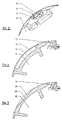
- Fig. 1
- eine schematische Darstellung eines Falzapparates mit dem erfindungsgemäß ausgebildeten Falzklappenzylinder;
- Fig. 2
- eine vergrößerte Darstellung des Bereiches des Punktur- und Falzmesserzylinders, in dem eine Schneidleiste und ein Nutenbalken dargestellt sind;
- Fig. 3
- eine erste Ausführungsform im Rahmen der Erfindung und
- Fig. 4
- eine zweite Ausführungsform im Rahmen der Erfindung.
- Fig. 1
- a schematic representation of a folding apparatus with the folding jaw cylinder designed according to the invention;
- Fig. 2
- an enlarged view of the area of the puncture and folding knife cylinder, in which a cutting bar and a grooved bar are shown;
- Fig. 3
- a first embodiment within the scope of the invention and
- Fig. 4
- a second embodiment within the scope of the invention.
Dem in Fig. 1 dargestellten Falzapparat 1 wird eine Bedruckstoffbahn 2 über Zugwalzen 3, 4 in üblicher Weise zugeführt. Die Bedruckstoffbahn 2 gelangt zwischen einen Schneidzylinder 5 und einen Punktur- und Falzmesserzylinder 6. Der Schneidzylinder 5 weist hier zwei gegenüberliegende Messer 7 auf. Der Punktur- und Falzmesserzylinder 6 ist an seiner Peripherie mit mehreren Schneidleisten 8 und Punkturen 9 ausgestattet. Selbstverständlich können auch im Rahmen der Erfindung anstelle der Punkturen 9 Greifer verwendet werden, um jeweils den Anfang der zugeführten Bedruckstoffbahn 2 zu erfassen, bevor jeweils der Zuschnitt eines Exemplares zwischen einem Messer 7 und einer Schneidleiste 8 erfolgt. Im hier dargestellten Ausführungsbeispiel nicht dargestellte, aus der Bedruckstoffbahn 2 zugeschnittene Exemplare werden über einen entsprechenden Umfangsbereich des Punktur- und Falzmesserzylinders 6 geführt, wonach mit Hilfe der Falzmesser 10 des Punktur- und Falzmesserzylinders 6 die Falzbildung erfolgt, in dem die Falzmesser 10 die auf dem Punktur- und Falzmesserzylinder 6 liegenden Exemplare in Falzklappen 13 des benachbarten bzw. nachgeordneten Falzklappenzylinders 12 stoßen. Die gefalzten Exemplare gelangen dann in üblicher Weise entlang eines Pfeiles 15 in ein Schaufelrad 14 und von diesem auf eine Bandleitung 16.The
Wie bereits beschrieben, kann im Bereich der Zentrale A zwischen den Zylindern 6 und 12 ein Papierstau auftreten, der eventuell eine Beschädigung an den Zylindern 6, 12 hervorrufen würde, wenn sich dieser zwischen den Zylindern 6, 12 hindurchbewegt. Da üblicherweise die bei 17 angedeutete Durchmesserverstellung eine Vergrößerung des Spaltes zwischen den Zylindern 6, 12 ermöglicht, wie vorangehend beschrieben wurde, ist in diesen Bereichen die Gefahr einer Beschädigung quasi gebannt.As already described, a paper jam may occur in the area of the center A between the
Hingegen im Bereich einer jeden Schneidleiste 8, die durch Nutenbalken bzw. Nutenbalken 11 jeweils gestützt sind, ist eine derartige Vergrößerung des Spaltes zwischen den Zylindern 6, 12 bei bekannten Falzapparaten nicht möglich, denn die Schneidleisten 8 und Nutenwalzen 11 können nicht "nachgiebig" ausgebildet werden, infolge der Funktion, die sie erfüllen müssen. Hierdurch entsteht eine erhebliche Gefahr, daß beim Durchgang des Papierstaues zwischen den Zylindern 6, 12 zu einem Zeitpunkt, zu dem die Schneidleisten 8 bzw. Nutenbalken 11 den Spalt durchlaufen, Teile des Falzapparates 1 zerstört werden können. Erfindungsgemäß wird deshalb in den den Schneidleisten 8 bzw. Nutenbalken 11 gegenüberliegenden Bereichen (das ist jeweils der Bereich zwischen benachbarten Falzklappen 13), der Mantel des Falzklappenzylinders mit Gruben 18 oder mit Abflachungen 20 versehen, wie die Fig. 3, 4 zeigen. Dadurch ergibt sich beim Überlaufen der Gruben 18 bzw. der Abflachungen 20 jeweils auch eine Vergrößerung des Spaltes zwischen den Zylindern 6, 12, so daß der Papierstau gefahrlos den Spalt zwischen den Zylindern 6, 12 passieren kann.In contrast, in the area of each
Falls die kreiszylindrische Mantelkontur des Falzklappenzylinders 12 beibehalten werden soll, können die Gruben 18 bzw. die Abflachungen 20 mit elastischen Abdeckelementen 19, 21 versehen werden, beispielsweise in Form von nebeneinander liegenden Elementen aus Federbandstahl oder aus einem geeignet elastischen Kunststoff, so daß die in Längsrichtung des Falzklappenzylinders 12 verlaufenden Gruben 18 bzw. Abflachungen 20 quasi überbrückt werden. Die jeweils dreifach vorhandenen Teile 13, 18, 19 wurden in Fig. 1 nur einmal aus Platzgründen mit Bezugszeichen vesehen.If the circular cylindrical jacket contour of the
Die Länge der Gruben 18 bzw. der Abflachungen 20 in Umfangsrichtung des Falzklappenzylinders 12 gesehen, kann durch Versuche ermittelt werden oder es kann der längstmöglichste Umfangsabschnitt jeweils zwischen zwei benachbarten Falzklappen 13 zur Erzeugung der Gruben 18 herangezogen werden, wie dies etwa bei der Ausführung gemäß Fig. 4 der Fall ist. Dadurch ist sichergestellt, daß in jedem Fall auftretende Stopper oder Papieranhäufungen den Spalt zwischen den Zylindern 6, 12 passieren können, ohne daß eine Beschädigungsgefahr auftritt.The length of the
Claims (2)
- Folding apparatus having a needle and folding blade cylinder (6) with cutting strips (8) and groove channels (11), against which is set a cutting cylinder (5) equipped with blades (7), and a folding jaw cylinder (12) connected downstream of the needle and folding blade cylinder (6), characterised in that between circumferentially adjacent folding jaws (13) of the folding jaw cylinder (12), troughs (18) or flattened surfaces (20) are respectively provided, also extending in the axial direction of the folding jaw cylinder (12), in such a way that when rolling past the gap between the folding jaw cylinder (12) and the needle and folding blade cylinder (6) a cutting strip (8) or a groove channel (11) is opposite a trough (18) or a flattened surface (20).
- Folding apparatus according to claim 1, characterised in that the troughs (18) and the flattened surface (20) on the folding jaw cylinder (12) are covered by resilient elements (19, 21) which, seen in the axial direction of the folding jaw cylinder (12), are arranged in segments next to each other.
Applications Claiming Priority (2)
| Application Number | Priority Date | Filing Date | Title |
|---|---|---|---|
| DE3932931A DE3932931A1 (en) | 1989-10-03 | 1989-10-03 | FOLDING VALVE CYLINDER FOR A FOLDING APPARATUS |
| DE3932931 | 1989-10-03 |
Publications (3)
| Publication Number | Publication Date |
|---|---|
| EP0421083A2 EP0421083A2 (en) | 1991-04-10 |
| EP0421083A3 EP0421083A3 (en) | 1991-05-22 |
| EP0421083B1 true EP0421083B1 (en) | 1994-02-02 |
Family
ID=6390718
Family Applications (1)
| Application Number | Title | Priority Date | Filing Date |
|---|---|---|---|
| EP90115007A Expired - Lifetime EP0421083B1 (en) | 1989-10-03 | 1990-08-04 | Folding jaw cylinder for folding machine |
Country Status (4)
| Country | Link |
|---|---|
| EP (1) | EP0421083B1 (en) |
| JP (1) | JPH03152061A (en) |
| CA (1) | CA2026240A1 (en) |
| DE (2) | DE3932931A1 (en) |
Families Citing this family (6)
| Publication number | Priority date | Publication date | Assignee | Title |
|---|---|---|---|---|
| DE4344622A1 (en) * | 1993-12-24 | 1995-06-29 | Koenig & Bauer Ag | Wheel folder for a rotary printing machine |
| US6250622B1 (en) * | 1999-05-20 | 2001-06-26 | Heidelberger Druckmaschinen Aktiengesellschaft | Cylinder assembly for a folding apparatus of a rotary printing press |
| DE10332646B4 (en) * | 2003-07-18 | 2005-11-03 | Koenig & Bauer Ag | Cylinder of a folder |
| DE102007019132B4 (en) * | 2007-04-20 | 2011-07-07 | manroland AG, 63075 | Insert for a jaw cylinder |
| DE102017103523A1 (en) * | 2017-02-21 | 2018-08-23 | Manroland Web Systems Gmbh | Insert for a jaw cylinder and method of making an insert for a jaw cylinder |
| DE102018108982A1 (en) * | 2018-04-16 | 2019-10-17 | Manroland Goss Web Systems Gmbh | Clamping lever for attaching machining tools to a rotatably mounted element of a printing press |
Family Cites Families (6)
| Publication number | Priority date | Publication date | Assignee | Title |
|---|---|---|---|---|
| GB396486A (en) * | 1931-03-19 | 1933-08-10 | Goss Printing Press Co Ltd | Improvements in or relating to folding mechanisms for paper or similar sheets |
| SE309425B (en) * | 1966-03-15 | 1969-03-24 | Winkler Fallert & Co Maschf | |
| DE2011661B1 (en) * | 1970-03-12 | 1971-07-15 | Maschinenfabrik Augsburg Nuernberg Ag | Fold measuring cylinders for rotary printing machines |
| DE3347719A1 (en) * | 1983-12-31 | 1985-07-11 | M.A.N.- Roland Druckmaschinen AG, 6050 Offenbach | Cross-folding device |
| DE3545295C1 (en) * | 1985-12-20 | 1986-10-16 | M.A.N.- Roland Druckmaschinen AG, 6050 Offenbach | Pull roller pair for a rotary printing machine for transporting printing material webs |
| DE3810439C1 (en) * | 1988-03-26 | 1989-08-10 | Man Roland Druckmaschinen Ag, 6050 Offenbach, De |
-
1989
- 1989-10-03 DE DE3932931A patent/DE3932931A1/en active Granted
-
1990
- 1990-08-04 EP EP90115007A patent/EP0421083B1/en not_active Expired - Lifetime
- 1990-08-04 DE DE90115007T patent/DE59004497D1/en not_active Expired - Lifetime
- 1990-09-26 CA CA002026240A patent/CA2026240A1/en not_active Abandoned
- 1990-10-03 JP JP2263971A patent/JPH03152061A/en active Pending
Also Published As
| Publication number | Publication date |
|---|---|
| DE59004497D1 (en) | 1994-03-17 |
| DE3932931C2 (en) | 1993-01-07 |
| DE3932931A1 (en) | 1991-04-11 |
| CA2026240A1 (en) | 1991-04-04 |
| EP0421083A3 (en) | 1991-05-22 |
| EP0421083A2 (en) | 1991-04-10 |
| JPH03152061A (en) | 1991-06-28 |
Similar Documents
| Publication | Publication Date | Title |
|---|---|---|
| EP0627310B1 (en) | Folding apparatus and method for crosswise folding | |
| DE2517000C2 (en) | Folding device for transversely and longitudinally folded or only longitudinally folded products | |
| DE2656267C3 (en) | Folder for web-fed rotary printing machines | |
| DE3721515C1 (en) | Device for distributing printed copies | |
| DE4340858C2 (en) | cylinder | |
| DE102005041180A1 (en) | Horizontal perforation device for folding apparatus of printing machine, has perforated cutter cylinder supported at frame in axially adjustable manner, and print substrate movable between perforated cutter cylinder and two-way cylinder | |
| EP0421083B1 (en) | Folding jaw cylinder for folding machine | |
| EP1116560B1 (en) | Cutting device with adjustable cutting lenght | |
| EP0019202A1 (en) | Folding device for a rotary printing machine | |
| DE19927920A1 (en) | Cutting device for folding apparatus of rotary printing press, in which one cylinder carries perforating cutter and other carries perforating counter-cutter | |
| CH615134A5 (en) | Folding apparatus for rotary printing machines having a magazine-cutting facility | |
| EP0264846B1 (en) | Folding apparatus with a transverse perforating device | |
| EP0156325B1 (en) | Apparatus for making a machine-made oblique fold in the leading edge of a continuous paper web | |
| DE10254332A1 (en) | folding cylinder | |
| DE10209214B4 (en) | cutter | |
| DE3146208A1 (en) | FOLDING APPARATUS | |
| EP1186561B1 (en) | Cutting device for cutting a web in a folding machine | |
| DE1132935B (en) | Drum folding device for cross folding and collecting on sheet-fed printing machines | |
| EP0029528B1 (en) | Rotary web printing machine with a web connecting device | |
| DE10110117A1 (en) | Folding cylinder used in web-fed printing presses has at least one expansion segment which forms effective diameter of cylinder and located between operator-side support and drive-side support and spaced away from at least one of them | |
| EP0703047A2 (en) | Perforating device | |
| DE10209190A1 (en) | Cutting device for cross cutting at least one material web | |
| DE102016216429B4 (en) | Printed product, method and web-fed printing machine for producing a printed product | |
| DE102004005807B4 (en) | folding | |
| DE102007039485A1 (en) | Method for operating a web-fed printing machine |
Legal Events
| Date | Code | Title | Description |
|---|---|---|---|
| PUAI | Public reference made under article 153(3) epc to a published international application that has entered the european phase |
Free format text: ORIGINAL CODE: 0009012 |
|
| PUAL | Search report despatched |
Free format text: ORIGINAL CODE: 0009013 |
|
| AK | Designated contracting states |
Kind code of ref document: A2 Designated state(s): CH DE FR GB IT LI |
|
| AK | Designated contracting states |
Kind code of ref document: A3 Designated state(s): CH DE FR GB IT LI |
|
| 17P | Request for examination filed |
Effective date: 19910419 |
|
| 17Q | First examination report despatched |
Effective date: 19930331 |
|
| ITF | It: translation for a ep patent filed | ||
| GRAA | (expected) grant |
Free format text: ORIGINAL CODE: 0009210 |
|
| AK | Designated contracting states |
Kind code of ref document: B1 Designated state(s): CH DE FR GB IT LI |
|
| GBT | Gb: translation of ep patent filed (gb section 77(6)(a)/1977) |
Effective date: 19940201 |
|
| REF | Corresponds to: |
Ref document number: 59004497 Country of ref document: DE Date of ref document: 19940317 |
|
| ET | Fr: translation filed | ||
| PLBE | No opposition filed within time limit |
Free format text: ORIGINAL CODE: 0009261 |
|
| STAA | Information on the status of an ep patent application or granted ep patent |
Free format text: STATUS: NO OPPOSITION FILED WITHIN TIME LIMIT |
|
| 26N | No opposition filed | ||
| REG | Reference to a national code |
Ref country code: GB Ref legal event code: IF02 |
|
| PGFP | Annual fee paid to national office [announced via postgrant information from national office to epo] |
Ref country code: CH Payment date: 20020717 Year of fee payment: 13 |
|
| PGFP | Annual fee paid to national office [announced via postgrant information from national office to epo] |
Ref country code: GB Payment date: 20020730 Year of fee payment: 13 |
|
| PGFP | Annual fee paid to national office [announced via postgrant information from national office to epo] |
Ref country code: FR Payment date: 20020812 Year of fee payment: 13 |
|
| PG25 | Lapsed in a contracting state [announced via postgrant information from national office to epo] |
Ref country code: GB Free format text: LAPSE BECAUSE OF NON-PAYMENT OF DUE FEES Effective date: 20030804 |
|
| PG25 | Lapsed in a contracting state [announced via postgrant information from national office to epo] |
Ref country code: CH Free format text: LAPSE BECAUSE OF NON-PAYMENT OF DUE FEES Effective date: 20030831 Ref country code: LI Free format text: LAPSE BECAUSE OF NON-PAYMENT OF DUE FEES Effective date: 20030831 |
|
| GBPC | Gb: european patent ceased through non-payment of renewal fee |
Effective date: 20030804 |
|
| REG | Reference to a national code |
Ref country code: CH Ref legal event code: PL |
|
| PG25 | Lapsed in a contracting state [announced via postgrant information from national office to epo] |
Ref country code: FR Free format text: LAPSE BECAUSE OF NON-PAYMENT OF DUE FEES Effective date: 20040430 |
|
| REG | Reference to a national code |
Ref country code: FR Ref legal event code: ST |
|
| PG25 | Lapsed in a contracting state [announced via postgrant information from national office to epo] |
Ref country code: IT Free format text: LAPSE BECAUSE OF NON-PAYMENT OF DUE FEES;WARNING: LAPSES OF ITALIAN PATENTS WITH EFFECTIVE DATE BEFORE 2007 MAY HAVE OCCURRED AT ANY TIME BEFORE 2007. THE CORRECT EFFECTIVE DATE MAY BE DIFFERENT FROM THE ONE RECORDED. Effective date: 20050804 |
|
| PGFP | Annual fee paid to national office [announced via postgrant information from national office to epo] |
Ref country code: DE Payment date: 20090821 Year of fee payment: 20 |
|
| PG25 | Lapsed in a contracting state [announced via postgrant information from national office to epo] |
Ref country code: DE Free format text: LAPSE BECAUSE OF EXPIRATION OF PROTECTION Effective date: 20100804 |