EP0419815A2 - Texturing machine - Google Patents
Texturing machine Download PDFInfo
- Publication number
- EP0419815A2 EP0419815A2 EP90115013A EP90115013A EP0419815A2 EP 0419815 A2 EP0419815 A2 EP 0419815A2 EP 90115013 A EP90115013 A EP 90115013A EP 90115013 A EP90115013 A EP 90115013A EP 0419815 A2 EP0419815 A2 EP 0419815A2
- Authority
- EP
- European Patent Office
- Prior art keywords
- winding
- units
- machine
- texturing
- longitudinal direction
- Prior art date
- Legal status (The legal status is an assumption and is not a legal conclusion. Google has not performed a legal analysis and makes no representation as to the accuracy of the status listed.)
- Withdrawn
Links
Images

Classifications
-
- D—TEXTILES; PAPER
- D02—YARNS; MECHANICAL FINISHING OF YARNS OR ROPES; WARPING OR BEAMING
- D02G—CRIMPING OR CURLING FIBRES, FILAMENTS, THREADS, OR YARNS; YARNS OR THREADS
- D02G1/00—Producing crimped or curled fibres, filaments, yarns, or threads, giving them latent characteristics
- D02G1/02—Producing crimped or curled fibres, filaments, yarns, or threads, giving them latent characteristics by twisting, fixing the twist and backtwisting, i.e. by imparting false twist
- D02G1/0206—Producing crimped or curled fibres, filaments, yarns, or threads, giving them latent characteristics by twisting, fixing the twist and backtwisting, i.e. by imparting false twist by false-twisting
- D02G1/0266—Producing crimped or curled fibres, filaments, yarns, or threads, giving them latent characteristics by twisting, fixing the twist and backtwisting, i.e. by imparting false twist by false-twisting false-twisting machines
Definitions
- the invention relates to a texturing machine with a plurality of working positions, each of which is assigned a holder for a supply spool, a heating device, a cooling section, a texturing unit, a set heater, a spooling unit and several delivery units, the spooling units of successive working positions being combined into groups which in the longitudinal direction of the machine, alternatingly arranged on one and the other side of an operating aisle in coil walls, each of which contains a set heater assigned to a group between the groups of winding units.
- Such winding units are of relatively low construction, but due to the arrangement of four winding units each accommodating one spool one above the other, a considerable overall height is inevitably obtained, which will cause problems with regard to machine operation. Likewise, such an arrangement complicates automation, in particular of changing bobbins.
- the invention has for its object to design a texturing machine of the type mentioned in such a way that several winding units can be combined into a group while nevertheless, the winding units are within easy reach for an operator or for a bobbin changing device.
- winding units arranged one above the other are provided with winding spindles oriented transversely to the machine longitudinal direction, which are directed inwards to the operating aisle, and in that each winding unit is designed to accommodate two bobbin tubes.
- the texturing machine shown in FIGS. 1 and 2 corresponds in its basic structure to DE-A 37 01 734.
- the texturing machine has a machine frame (10) which delimits a wide operating aisle with two winding walls (11, 12). It contains a large number of working positions, each grouped into groups of four.
- the groups following one another in the longitudinal direction of the machine are designed and arranged in such a way that the threads of one group from the left over the service aisle and those of the following group from the right over the Operating aisle run.
- the threads (13) of the first group are drawn off on the left-hand side of the machine in FIG. 1 by means of delivery mechanisms (14) from supply bobbins, not shown, which are held in fixed or movable bobbins.
- the first delivery unit (14) is located at the top of the service aisle. This is followed by a heating device (15) designed for the group of four threads (13), which is inclined obliquely to the opposite side of the operating aisle. A suction device (16) and cooling rails (17) adjoin this heating device (15), which is followed correspondingly by a group of four texturing units (18) which is arranged on the right side of the operating aisle. Feeding units (19) adjoin the texturing units (18), which are arranged above a set heater (20) designed for the group of four threads. Below the set heater (20) there are delivery mechanisms (21) which, via thread guide elements (22, 23, 24), distribute the threads onto two winding units (25, 26), which wind the threads onto spools (27, 28, 29, 30) .
- Another group of four working positions follows, in which the arrangement of the individual elements is mirror-inverted, so that there is a direction of travel for the threads (13 ') from the right to the left side of the operating aisle.
- the threads (13 ') run over delivery units (14'), a heating device (15 '), a suction device (16'), cooling rails (17 '), texturing units (18'), delivery units (19 '), a set heater (20 '), Supply mechanisms (21') and thread guide elements (22 ', 23' and 24 ') to bobbin units (25', 26 ') and are wound to bobbins (27', 28 'and 29', 30 ').
- the group of four threads runs from the delivery units (21) under the set heater (20) to thread guides (22), from which they are guided in pairs to thread guides (31, 23) which they are redirected upwards.
- the thread guides assigned to the lower winding units (25) form the starting point for a traversing triangle. From the thread guides lying at the same height (31) the threads are first deflected upwards to thread guides (24), which are approximately at the level of the winding units (25), from which the traversing triangles then emanate.
- Each of the winding devices (25, 26) contains a traversing thread guide (32), a friction roller (33) and a winding spindle (34), which a clamping device for the sleeves of the bobbins (27, 28, 29 , 30) contains.
- the friction roller (33) and the traversing thread guide (32), which contains two thread guide elements are arranged substantially perpendicularly below the winding spindles (34).
- the winding units (25, 26) are arranged somewhat offset in the longitudinal direction of the machine, so that the threads to the upper winding unit (26) can easily be guided past the lower winding unit (25) and the bobbins (27, 28) located there.
- the set heaters (20, 20 ') are integrated in the coil walls (11, 12). On the operating side, they are aligned with housings which contain the drives and gears for the friction rollers (33) and the traversing devices (32). Since the texturing units (18, 18 ′) are arranged alternately in groups of four on both sides of the operating aisle, the overall length of the texturing machine is not determined solely by the dimensions of the texturing units (18, 18 ′) in the machine longitudinal direction.
- the delivery mechanisms (14, 19, 21; 14 ', 19', 21 ') each contain continuous shafts in the machine longitudinal direction, which are driven by individual drive motors (35) arranged at the machine end.
- the continuous drive shafts are assigned to each of the threads (13,13 ') spring-loaded pressure rollers.
Landscapes
- Engineering & Computer Science (AREA)
- Mechanical Engineering (AREA)
- Textile Engineering (AREA)
- Yarns And Mechanical Finishing Of Yarns Or Ropes (AREA)
- Warping, Beaming, Or Leasing (AREA)
Abstract
Description
Die Erfindung betrifft eine Texturiermaschine mit einer Vielzahl von Arbeitspositionen, denen jeweils eine Halterung für eine Vorlagespule, eine Heizeinrichtung, eine Kühlstrecke, ein Texturieraggregat, ein Setheizer, ein Spulaggregat und mehrere Lieferwerke zugeordnet sind, wobei die Spulaggregate aufeinanderfolgender Arbeitspositionen zu Gruppen zusammengefaßt sind, die in Maschinenlängsrichtung aufeinanderfolgend abwechselnd auf der einen und der anderen Seite eines Bedienungsganges in Spulenwänden angeordnet sind, die zwischen den Gruppen von Spulaggregaten jeweils einen einer Gruppe zugeordneten Setheizer enthalten.The invention relates to a texturing machine with a plurality of working positions, each of which is assigned a holder for a supply spool, a heating device, a cooling section, a texturing unit, a set heater, a spooling unit and several delivery units, the spooling units of successive working positions being combined into groups which in the longitudinal direction of the machine, alternatingly arranged on one and the other side of an operating aisle in coil walls, each of which contains a set heater assigned to a group between the groups of winding units.
Mit einer bekannten Texturiermaschine der eingangs genannten Art (DE-A 37 01 734) wird insgesamt eine vorteilhafte Gestaltung geschaffen, die eine Reduzierung der Bauhöhe der Texturiermaschine und ihrer Baulänge gestattet. Dabei werden Gruppen von vier Spulaggregaten gebildet, die übereinander angeordnet sind. Die Spulspindeln verlaufen in Maschinenlängsrichtung. Auch wenn die Spulaggregate in der Tiefe der Spulenwände etwas versetzt zueinander angeordnet sind, benötigen sie eine relativ große Bauhöhe. Dies führt dazu, daß es für eine Bedienungsperson schwierig sein kann, ohne ein Podest o.dgl. das oberste Spulaggregat zu erreichen und beispielsweise dort eine Spule zu entnehmen.With a known texturing machine of the type mentioned at the outset (DE-A 37 01 734), an advantageous design is created overall, which permits a reduction in the overall height of the texturing machine and in its overall length. Groups of four winding units are formed, which are arranged one above the other. The winding spindles run in the machine longitudinal direction. Even if the winding units are slightly offset from one another in the depth of the coil walls, they require a relatively large overall height. As a result, it can be difficult for an operator to do so without a pedestal or the like. the top one To reach the winding unit and, for example, remove a bobbin there.
Es ist auch bei einer Texturiermaschine bekannt (DE-A 37 18 148), jeweils vier Spulaggregate von aufeinanderfolgenden Arbeitspositionen in einer Säule übereinander anzuordnen, wobei zwischen den Säulen mit den Spulaggregaten jeweils Setheizer angeordnet sind. Die Setheizer und die Säulen mit den Spulaggregaten sind in zwei spiegelbildlich zueinander angeordneten Reihen in der Mitte einer Maschine angeordnet und befinden sich somit zwischen zwei Bedienungsgängen.Die jeweils einer Arbeitsposition zugehörigen Heizeinrichtung und Kühlzone befinden sich oberhalb des jeweiligen Bedienungsganges. Bei dieser Bauart besitzen die in einer Säule angeordneten Spulaggregate angetriebene Spulspindeln, denen in einer Horizontalebene davor angeordnete Changierfadenführer zugeordnet sind. Diese Changierfadenführer sind in Halterungen verschiebbar, so daß sie in horizontaler Richtung entsprechend dem wachsenden Spulendurchmesser ausweichen können. Derartige Spulaggregate bauen zwar relativ niedrig, jedoch wird dennoch aufgrund der Anordnung von vier jeweils eine Spule aufnehmenden Spulaggregaten übereinander zwangsläufig eine erhebliche Bauhöhe erhalten, die bezüglich der Maschinenbedienung Probleme mit sich bringen wird. Ebenso wird durch eine derartige Anordnung eine Automation insbesondere eines Spulenwechsels kompliziert.It is also known in a texturing machine (DE-A 37 18 148) to arrange four winding units from successive working positions one above the other in a column, set heaters being arranged between the columns with the winding units. The set heaters and the columns with the winding units are arranged in two mirror-inverted rows in the middle of a machine and are therefore located between two operating aisles. The heating device and cooling zone associated with each working position are located above the respective operating aisle. In this design, the winding units arranged in a column have driven winding spindles, to which traversing thread guides arranged in a horizontal plane are assigned. These traversing thread guides are displaceable in holders so that they can dodge in the horizontal direction in accordance with the growing bobbin diameter. Such winding units are of relatively low construction, but due to the arrangement of four winding units each accommodating one spool one above the other, a considerable overall height is inevitably obtained, which will cause problems with regard to machine operation. Likewise, such an arrangement complicates automation, in particular of changing bobbins.
Bei Textilmaschinen, insbesondere Spinnmaschinen für Chemiefasern, war es bekannt, Spulaggregate so anzuordnen, daß die Spulspindeln in einer gemeinsamen Horizontalebene liegen und lotrecht von der Maschinenfront abragen. Bei dieser Bauart ist ferner vorgesehen, daß die Spulspindel mit Spannfuttern für jeweils zwei Spulenhülsen versehen sind.In textile machines, in particular spinning machines for man-made fibers, it was known to arrange winding units in such a way that the winding spindles lie in a common horizontal plane and project perpendicularly from the machine front. In this type it is also provided that the winding spindle are provided with chucks for two bobbin tubes.
Der Erfindung liegt die Aufgabe zugrunde,eine Texturiermaschine der eingangs genannten Art so auszubilden, daß mehrere Spulaggregate zu einer Gruppe zusammengefaßt werden können, während dennoch die Spulaggregate in einer bequemen Reichweite für eine Bedienungsperson oder für eine Spulenwechseleinrichtung liegen.The invention has for its object to design a texturing machine of the type mentioned in such a way that several winding units can be combined into a group while nevertheless, the winding units are within easy reach for an operator or for a bobbin changing device.
Diese Aufgabe wird dadurch gelöst, daß die in zwei Reihen übereinander angeordneten Spulaggregate mit quer zur Maschinenlängsrichtung gerichteten Spulspindeln versehen sind, die nach innen zum Bedienungsgang gerichtet sind, und daß jedes Spulaggregat auf die Aufnahme von zwei Spulenhülsen ausgelegt ist.This object is achieved in that the winding units arranged one above the other are provided with winding spindles oriented transversely to the machine longitudinal direction, which are directed inwards to the operating aisle, and in that each winding unit is designed to accommodate two bobbin tubes.
Da bei dieser Texturiermaschine ein breiter Bedienungsgang vorhanden ist, führt das Abragen der Spulaggregate von den beiden Spulenwänden nicht zu einer nennenswerten Beeinträchtigung. Dagegen ist es in vorteilhafter Weise möglich, die Spulaggregate für vier Spulen innerhalb einer geringen Bauhöhe unterzubringen, so daß die Spulaggregate und die Spulen für Bedienungspersonen oder eine Spulenwechseleinrichtung bequem zugänglich sind.Since there is a wide operating aisle in this texturing machine, the removal of the winding units from the two coil walls does not lead to any appreciable impairment. In contrast, it is advantageously possible to accommodate the bobbin units for four bobbins within a small construction height, so that the bobbin units and the bobbins are easily accessible for operators or a bobbin changing device.
Weitere Merkmale und Vorteile der Erfindung ergeben sich aus der nachfolgenden Beschreibung der in der Zeichnung dargestellten Ausführungsform und den Unteransprüchen.
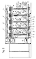
- Fig. 1 zeigt eine Ansicht in Längsrichtung einer erfindungsgemäßen Texturiermaschine und
- Fig. 2 eine Ansicht in Richtung des Pfeiles II auf eine der beiden einen Bedienungsgang begrenzenden Spulenwände.
- Fig. 1 shows a view in the longitudinal direction of a texturing machine according to the invention and
- Fig. 2 is a view in the direction of arrow II on one of the two coil walls delimiting an operating aisle.
Die in Fig. 1 und 2 dargestellte Texturiermaschine entspricht in ihrem Grundaufbau der DE-A 37 01 734. Die Texturiermaschine weist einen Maschinenrahmen (10) auf, der einen breiten Bedienungsgang mit zwei Spulwänden (11, 12) begrenzt. Sie enthält eine Vielzahl von Arbeitspositionen, die jeweils zu Vierergruppen zusammengefaßt sind. Die in Maschinenlängsrichtung hintereinanderfolgenden Gruppen sind so ausgebildet und angeordnet, daß die Fäden der einen Gruppe von links über den Bedienungsgang und die der darauf folgenden Gruppe von rechts über den Bedienungsgang laufen. Die Fäden (13) der ersten Gruppe werden auf der in Fig. 1 linken Maschinenseite mittels Lieferwerken (14) von nicht dargestellten Vorlagespulen abgezogen, die in festen oder verfahrbaren Spulengattern gehalten sind. Das erste Lieferwerk (14) befindet sich an der Oberseite des Bedienungsganges. Ihm folgt eine jeweils für die Gruppe von vier Fäden (13) ausgelegte Heizeinrichtung (15), die schräg zur gegenüberliegenden Seite des Bedienungsgangs geneigt ist. An dieser Heizeinrichtung (15) schließen eine Absaugeinrichtung (16) und Kühlschienen (17) an, der entsprechend eine Gruppe von vier Texturieraggregaten (18) folgt, die auf der rechten Seite des Bedienungsgangs angeordnet ist. An die Texturieraggregate (18) schließen Lieferwerke (19) an, die oberhalb eines für die Gruppe von vier Fäden ausgelegten Setheizers (20) angeordnet sind. Unterhalb des Setheizers (20) befinden sich Lieferwerke (21), die über Fadenführungselemente (22, 23, 24) die Fäden auf zwei Spulaggregate (25, 26) verteilen, die die Fäden auf Spulen (27, 28, 29, 30) aufwinden. Nach jeweils einer Gruppe von vier Arbeitspositionen folgt eine weitere Gruppe von vier Arbeitspositionen, bei der die Anordnung der einzelnen Elemente spiegelbildlich ist, so daß sich eine Laufrichtung für die Fäden (13′) von der rechten zur linken Seite des Bedienungsgangs ergibt. Die Fäden (13′) laufen über Lieferwerke (14′), einer Heizeinrichtung (15′), eine Absaugeinrichtung (16′), Kühlschienen (17′), Texturieraggregate (18′), Lieferwerke (19′), einen Setheizer (20′), Lieferwerke (21′) und Fadenführungselemente (22′,23′ und 24′) zu Spulaggregaten (25′,26′) und werden zu Spulen (27′,28′ und 29′,30′) aufgespult.The texturing machine shown in FIGS. 1 and 2 corresponds in its basic structure to DE-A 37 01 734. The texturing machine has a machine frame (10) which delimits a wide operating aisle with two winding walls (11, 12). It contains a large number of working positions, each grouped into groups of four. The groups following one another in the longitudinal direction of the machine are designed and arranged in such a way that the threads of one group from the left over the service aisle and those of the following group from the right over the Operating aisle run. The threads (13) of the first group are drawn off on the left-hand side of the machine in FIG. 1 by means of delivery mechanisms (14) from supply bobbins, not shown, which are held in fixed or movable bobbins. The first delivery unit (14) is located at the top of the service aisle. This is followed by a heating device (15) designed for the group of four threads (13), which is inclined obliquely to the opposite side of the operating aisle. A suction device (16) and cooling rails (17) adjoin this heating device (15), which is followed correspondingly by a group of four texturing units (18) which is arranged on the right side of the operating aisle. Feeding units (19) adjoin the texturing units (18), which are arranged above a set heater (20) designed for the group of four threads. Below the set heater (20) there are delivery mechanisms (21) which, via thread guide elements (22, 23, 24), distribute the threads onto two winding units (25, 26), which wind the threads onto spools (27, 28, 29, 30) . After each group of four working positions, another group of four working positions follows, in which the arrangement of the individual elements is mirror-inverted, so that there is a direction of travel for the threads (13 ') from the right to the left side of the operating aisle. The threads (13 ') run over delivery units (14'), a heating device (15 '), a suction device (16'), cooling rails (17 '), texturing units (18'), delivery units (19 '), a set heater (20 '), Supply mechanisms (21') and thread guide elements (22 ', 23' and 24 ') to bobbin units (25', 26 ') and are wound to bobbins (27', 28 'and 29', 30 ').
Wie aus Fig. 2 zu ersehen ist, läuft die Gruppe von vier Fäden jeweils von den Lieferwerken (21) unter dem Setheizer (20) zunächst zu Fadenführungen (22), von denen sie paarweise zu Fadenführungen (31, 23) geführt werden, an denen sie nach oben umgelenkt werden. Die den unteren Spulaggregaten (25) zugeordneten Fadenführungen bilden den Ausgangspunkt für ein Changierdreieck. Von den auf gleicher Höhe liegenden Fadenführungen (31) werden die Fäden zunächst noch zu Fadenführungen (24) nach oben umgelenkt, die etwa auf Höhe der Spulaggregate (25) liegen, von denen dann die Changierdreiecke ausgehen.As can be seen from Fig. 2, the group of four threads runs from the delivery units (21) under the set heater (20) to thread guides (22), from which they are guided in pairs to thread guides (31, 23) which they are redirected upwards. The thread guides assigned to the lower winding units (25) form the starting point for a traversing triangle. From the thread guides lying at the same height (31) the threads are first deflected upwards to thread guides (24), which are approximately at the level of the winding units (25), from which the traversing triangles then emanate.
Jede der Spuleinrichtungen (25, 26) (sowie auch 25′,26′) enthält einen Changierfadenführer (32), eine Friktionswalze (33) und eine Spulspindel (34), die eine Aufspanneinrichtung für die Hülsen der Spulen (27, 28, 29, 30) enthält. Aus Fig. 2 ist zu ersehen, daß die Friktionswalze (33) und der Changierfadenführer (32), der zwei Fadenführungselemente enthält, im wesentlichen lotrecht unterhalb den Spulspindeln (34) angeordnet sind. Die Spulaggregate (25, 26) sind etwas in Maschinenlängsrichtung versetzt angeordnet, so daß die Fäden zum oberen Spulaggregat (26) bequem an dem unteren Spulaggregat (25) und den dort befindlichen Spulen (27, 28) vorbeigeführt werden können.Each of the winding devices (25, 26) (and also 25 ', 26') contains a traversing thread guide (32), a friction roller (33) and a winding spindle (34), which a clamping device for the sleeves of the bobbins (27, 28, 29 , 30) contains. From Fig. 2 it can be seen that the friction roller (33) and the traversing thread guide (32), which contains two thread guide elements, are arranged substantially perpendicularly below the winding spindles (34). The winding units (25, 26) are arranged somewhat offset in the longitudinal direction of the machine, so that the threads to the upper winding unit (26) can easily be guided past the lower winding unit (25) and the bobbins (27, 28) located there.
Wie aus Fig. 1 und 2 zu ersehen ist, sind die Setheizer (20, 20′) in die Spulenwände (11, 12) integriert. Sie fluchten auf der Bedienungsseite mit Gehäusen, die die Antriebe und Getriebe für die Friktionswalzen (33) und die Changiereinrichtungen (32) enthalten. Da die Texturieraggregate (18, 18′) abwechselnd in Vierergruppen auf beiden Seiten des Bedienungsgangs angeordnet sind, wird die Gesamtlänge der Texturiermaschine nicht ausschließlich durch die Abmessungen der Texturieraggregate (18, 18′) in Maschinenlängsrichtung bestimmt.Es ist deshalb möglich, die Setheizer (20, 20′) und die Spulaggregate (25,26; 25′,26′) so anzuordnen, daß die zugehörigen Fadenführungselemente (22, 23, 24, 31) so angeordnet werden können, daß der Bereich vor den Setheizern (20, 20′) völlig frei liegt, so daß diese für Wartungsarbeiten frei zugänglich sind. Die Lieferwerke (14,19, 21; 14′,19′,21′) enthalten jeweils in Maschinenlängsrichtung durchlaufende Wellen, die von am Maschinenende angeordneten einzelnen Antriebsmotoren (35) angetrieben werden. Den durchlaufenden Antriebswellen sind für jeden der Fäden (13,13′) federnd angedrückte Druckrollen zugeordnet.As can be seen from FIGS. 1 and 2, the set heaters (20, 20 ') are integrated in the coil walls (11, 12). On the operating side, they are aligned with housings which contain the drives and gears for the friction rollers (33) and the traversing devices (32). Since the texturing units (18, 18 ′) are arranged alternately in groups of four on both sides of the operating aisle, the overall length of the texturing machine is not determined solely by the dimensions of the texturing units (18, 18 ′) in the machine longitudinal direction. 20, 20 ') and the winding units (25,26; 25', 26 ') to be arranged so that the associated thread guide elements (22, 23, 24, 31) can be arranged so that the area in front of the set heaters (20, 20th ') Is completely free, so that they are freely accessible for maintenance work. The delivery mechanisms (14, 19, 21; 14 ', 19', 21 ') each contain continuous shafts in the machine longitudinal direction, which are driven by individual drive motors (35) arranged at the machine end. The continuous drive shafts are assigned to each of the threads (13,13 ') spring-loaded pressure rollers.
Claims (4)
Applications Claiming Priority (2)
| Application Number | Priority Date | Filing Date | Title |
|---|---|---|---|
| DE3931878 | 1989-09-23 | ||
| DE19893931878 DE3931878C2 (en) | 1989-09-23 | 1989-09-23 | Texturing machine |
Publications (2)
| Publication Number | Publication Date |
|---|---|
| EP0419815A2 true EP0419815A2 (en) | 1991-04-03 |
| EP0419815A3 EP0419815A3 (en) | 1991-05-22 |
Family
ID=6390099
Family Applications (1)
| Application Number | Title | Priority Date | Filing Date |
|---|---|---|---|
| EP19900115013 Withdrawn EP0419815A3 (en) | 1989-09-23 | 1990-08-04 | Texturing machine |
Country Status (3)
| Country | Link |
|---|---|
| EP (1) | EP0419815A3 (en) |
| JP (1) | JP3037983B2 (en) |
| DE (1) | DE3931878C2 (en) |
Cited By (4)
| Publication number | Priority date | Publication date | Assignee | Title |
|---|---|---|---|---|
| EP0659913A1 (en) * | 1993-12-24 | 1995-06-28 | MENEGATTO S.r.l. | Texturing machine |
| FR2865220A1 (en) * | 2004-01-16 | 2005-07-22 | Rieter Textile Machinery Fr | Textile yarn transformation unit has texturing, fixing and winding assemblies positioned in two separate zones for maintenance and intervention |
| WO2014198631A1 (en) * | 2013-06-11 | 2014-12-18 | Oerlikon Textile Gmbh & Co. Kg | Texturing machine |
| WO2016065961A1 (en) * | 2014-10-29 | 2016-05-06 | 无锡宏源机电科技股份有限公司 | Efficient multifunctional fibre machinery |
Families Citing this family (4)
| Publication number | Priority date | Publication date | Assignee | Title |
|---|---|---|---|---|
| DE102013006626A1 (en) | 2013-04-18 | 2014-10-23 | Oerlikon Textile Gmbh & Co. Kg | texturing |
| DE102013007254A1 (en) | 2013-04-26 | 2014-10-30 | Oerlikon Textile Gmbh & Co. Kg | False twist |
| CN105683430B (en) * | 2013-11-02 | 2018-08-14 | 欧瑞康纺织有限及两合公司 | Texturing machine |
| CN105752753B (en) * | 2014-12-18 | 2019-05-21 | 欧瑞康纺织有限及两合公司 | Weaving loom |
Citations (3)
| Publication number | Priority date | Publication date | Assignee | Title |
|---|---|---|---|---|
| FR1442765A (en) * | 1965-07-22 | 1966-06-17 | Sulzer Ag | Twisting loom for the production of crimped yarn |
| US3316699A (en) * | 1963-10-16 | 1967-05-02 | Klinger Mfg Co Ltd | Apparatus for twisting yarn |
| FR2332353A1 (en) * | 1975-11-19 | 1977-06-17 | Roannais Const Textiles Atel | Frame with yarn false twisters - has central creel for yarn supply producing two walkways for machine operators |
Family Cites Families (4)
| Publication number | Priority date | Publication date | Assignee | Title |
|---|---|---|---|---|
| DE3136908A1 (en) * | 1980-09-19 | 1982-05-06 | Barmag Barmer Maschinenfabrik Ag, 5630 Remscheid | Winding machine for the winding of a plurality of threads |
| DE3324243A1 (en) * | 1982-07-09 | 1984-02-16 | Barmag Barmer Maschinenfabrik Ag, 5630 Remscheid | False-twist crimping machine and process for bridging brief voltage losses on textile machines |
| DE3701734A1 (en) * | 1986-02-01 | 1987-08-06 | Zinser Textilmaschinen Gmbh | TEXTURING MACHINE FOR FALSEWIRE CRAWLING SYNTHETIC THREADS |
| DE3718148A1 (en) * | 1986-06-03 | 1987-12-23 | Barmag Barmer Maschf | False-twist crimping machine |
-
1989
- 1989-09-23 DE DE19893931878 patent/DE3931878C2/en not_active Expired - Fee Related
-
1990
- 1990-08-04 EP EP19900115013 patent/EP0419815A3/en not_active Withdrawn
- 1990-09-21 JP JP2250470A patent/JP3037983B2/en not_active Expired - Lifetime
Patent Citations (3)
| Publication number | Priority date | Publication date | Assignee | Title |
|---|---|---|---|---|
| US3316699A (en) * | 1963-10-16 | 1967-05-02 | Klinger Mfg Co Ltd | Apparatus for twisting yarn |
| FR1442765A (en) * | 1965-07-22 | 1966-06-17 | Sulzer Ag | Twisting loom for the production of crimped yarn |
| FR2332353A1 (en) * | 1975-11-19 | 1977-06-17 | Roannais Const Textiles Atel | Frame with yarn false twisters - has central creel for yarn supply producing two walkways for machine operators |
Cited By (7)
| Publication number | Priority date | Publication date | Assignee | Title |
|---|---|---|---|---|
| EP0659913A1 (en) * | 1993-12-24 | 1995-06-28 | MENEGATTO S.r.l. | Texturing machine |
| US5515586A (en) * | 1993-12-24 | 1996-05-14 | Menegatto S.R.L. | Textile machine for texturing yarn by thermoplastic deformation |
| FR2865220A1 (en) * | 2004-01-16 | 2005-07-22 | Rieter Textile Machinery Fr | Textile yarn transformation unit has texturing, fixing and winding assemblies positioned in two separate zones for maintenance and intervention |
| WO2005078176A1 (en) * | 2004-01-16 | 2005-08-25 | Rieter Textile Machinery France | Unit for the transformation of textile threads |
| WO2014198631A1 (en) * | 2013-06-11 | 2014-12-18 | Oerlikon Textile Gmbh & Co. Kg | Texturing machine |
| CN105378164A (en) * | 2013-06-11 | 2016-03-02 | 欧瑞康纺织有限及两合公司 | Texturing machine |
| WO2016065961A1 (en) * | 2014-10-29 | 2016-05-06 | 无锡宏源机电科技股份有限公司 | Efficient multifunctional fibre machinery |
Also Published As
| Publication number | Publication date |
|---|---|
| JP3037983B2 (en) | 2000-05-08 |
| JPH03119131A (en) | 1991-05-21 |
| DE3931878A1 (en) | 1991-04-04 |
| EP0419815A3 (en) | 1991-05-22 |
| DE3931878C2 (en) | 1999-04-01 |
Similar Documents
| Publication | Publication Date | Title |
|---|---|---|
| WO2005118921A1 (en) | Apparatus for spinning and winding several synthetic threads | |
| DE1907782C3 (en) | Spinning draw winder | |
| WO2018134048A1 (en) | Winding machine | |
| DE3931878C2 (en) | Texturing machine | |
| DE102013109530A1 (en) | Textile machine for texturizing threads in processing locations during production of synthetic fibers, has winding frame holding winding device of processing location at outer machine longitudinal side, which faces away from platform | |
| EP3008232B1 (en) | Texturing machine | |
| DE102009013974A1 (en) | Device for melt spinning and rolling of threads to coils during production of synthetic threads, has upper doffing plane evacuating coils and formed by platform above lower winding machine, where platform carries upper winding machine | |
| CH671976A5 (en) | ||
| EP1523592B1 (en) | False twist texturing machine | |
| CH701660B1 (en) | False twist. | |
| DE10355294A1 (en) | spinning plant | |
| DE102006061332A1 (en) | Device for melt spinning, treating and winding synthetic threads, comprises a spinning unit, a treatment unit and a winding unit, which are arranged in tiers one above the other and form a single-thread or multi-thread production positions | |
| DE102017010143A1 (en) | Device for removing and winding a plurality of threads | |
| WO2018153739A1 (en) | Melt-spinning device | |
| EP0284945B1 (en) | Air jet texturing apparatus | |
| EP2971293A1 (en) | Device for melt-spinning, drawing and winding up a plurality of synthetic threads | |
| WO2011098368A1 (en) | Device for drawing and winding a plurality of synthetic threads | |
| DE102020004857A1 (en) | Device for drawing and winding threads | |
| DE102022112853B3 (en) | Device for winding a bundle of threads | |
| DE102017000607A1 (en) | Apparatus for stripping, drawing and winding a synthetic yarn sheet | |
| DE3735752C2 (en) | Process for the production of plain yarn from polyamide or polyester | |
| DE102021107995B4 (en) | thread manufacturing plant | |
| WO2014170185A1 (en) | Texturing machine | |
| WO2014173765A1 (en) | False twist texturing machine | |
| DE102010033579A1 (en) | Apparatus for winding synthetic yarns in a melt spinning process, has godet unit and two mirror-symmetrically arranged indexed winding stations, where godet unit has guide shell oriented transverse to winding spindles |
Legal Events
| Date | Code | Title | Description |
|---|---|---|---|
| PUAI | Public reference made under article 153(3) epc to a published international application that has entered the european phase |
Free format text: ORIGINAL CODE: 0009012 |
|
| PUAL | Search report despatched |
Free format text: ORIGINAL CODE: 0009013 |
|
| AK | Designated contracting states |
Kind code of ref document: A2 Designated state(s): CH DE FR IT LI |
|
| AK | Designated contracting states |
Kind code of ref document: A3 Designated state(s): CH DE FR IT LI |
|
| STAA | Information on the status of an ep patent application or granted ep patent |
Free format text: STATUS: THE APPLICATION IS DEEMED TO BE WITHDRAWN |
|
| 18D | Application deemed to be withdrawn |
Effective date: 19911123 |