EP0418496B1 - Electrical installation apparatus, especially safety socket - Google Patents
Electrical installation apparatus, especially safety socket Download PDFInfo
- Publication number
- EP0418496B1 EP0418496B1 EP90113924A EP90113924A EP0418496B1 EP 0418496 B1 EP0418496 B1 EP 0418496B1 EP 90113924 A EP90113924 A EP 90113924A EP 90113924 A EP90113924 A EP 90113924A EP 0418496 B1 EP0418496 B1 EP 0418496B1
- Authority
- EP
- European Patent Office
- Prior art keywords
- installation apparatus
- support ring
- insulating material
- base
- housing
- Prior art date
- Legal status (The legal status is an assumption and is not a legal conclusion. Google has not performed a legal analysis and makes no representation as to the accuracy of the status listed.)
- Expired - Lifetime
Links
Images

Classifications
-
- H—ELECTRICITY
- H01—ELECTRIC ELEMENTS
- H01R—ELECTRICALLY-CONDUCTIVE CONNECTIONS; STRUCTURAL ASSOCIATIONS OF A PLURALITY OF MUTUALLY-INSULATED ELECTRICAL CONNECTING ELEMENTS; COUPLING DEVICES; CURRENT COLLECTORS
- H01R13/00—Details of coupling devices of the kinds covered by groups H01R12/70 or H01R24/00 - H01R33/00
- H01R13/66—Structural association with built-in electrical component
- H01R13/665—Structural association with built-in electrical component with built-in electronic circuit
- H01R13/6691—Structural association with built-in electrical component with built-in electronic circuit with built-in signalling means
Definitions
- the invention relates to an electrical installation device, in particular a protective contact socket, with an insulating base held by a supporting ring having supporting webs, which in addition to the electrical contacts, the earthing clip and mechanical holding elements additionally has a circuit board with surge protection elements, the effectiveness of which can be indicated by a signaling device assigned to the circuit board , wherein the support ring can be connected to a receptacle comprising these components, such as a flush-mounted box.
- Electrical installation devices of this type are known in numerous embodiments. They have the advantage in themselves that they protect the devices connected to the socket from overvoltage. This is because they have a circuit board with overvoltage protection elements in the area of their insulating base. These can be destroyed in the event of very high-energy overvoltages, so that the protective circuit becomes inoperative.
- the optical signaling devices are difficult for the user to recognize, in the other case, when there are many indicator lamps in the same room, it can easily be overlooked that the red lamp of the installation device lights up and indicates that the overvoltage protection element is defective.
- an acoustic signaling device is used as the signaling device.
- a socket with surge protection with an acoustic display of a defect in the surge protection is known.
- This document relates to a socket with overvoltage protection, which is installed on or in the socket base, for example in the form of an additional module attached to the socket base, whereby a defect in the overvoltage protection is indicated.
- an acoustic display is provided as the display and that the means of this acoustic display are in the socket or on or in the socket base.
- an acoustic signal device has considerable advantages over the known optical signal devices. Since an acoustic signaling device e.g. emits a continuous tone, it is practically impossible for the user of such an electrical socket that he is not made aware that the overvoltage protection device of the installation device has failed and that remedial action must therefore be taken. Such an acoustic signal device is unmistakable not only in very bright rooms, but also in rooms with many display devices.
- an electronic, acoustic signal transmitter of known design is proposed, but it is also provided that signal transmitters are known as so-called buzzers.
- the invention now seeks to remedy this. It is based on the object of providing an encapsulated structural unit in the case of an installation device with an overvoltage protection device and a signal device of the type specified, which can be attached to existing components of the installation device without separate connecting means.
- the insulating base and the circuit board with the components assigned to it are surrounded by an insulating housing which can be fixed on existing receptacles of the supporting ring of the socket.
- the electrical installation device designed according to the invention has considerable advantages over the known embodiments since, on the one hand, suitable protection of the insulating base of the circuit board with the overvoltage protection elements and the signaling device is guaranteed against damage during storage and transport. Furthermore, the already existing receptacles or openings on the support ring, for example the socket, serve to fix them on the installation device. As a result, neither a change in the insulating material base nor in the support ring of the electrical installation device is necessary, so that the existing production tools can continue to be used for such an installation device.
- the insulating material housing is fastened to the retaining webs of the support ring of the installation device.
- Such a fastening is preferred in which the usual expanding claws of the retaining webs of the support ring are removed.
- the boundary walls of the openings provided for the expanding claws now serve as counter-latching for latching the insulating material housing.
- the expansion claws can be removed without any problems because they are usually detachably attached to the base by means of a screw. By removing this fastening screw, you can remove the expansion claw without having to change the insulating base.
- the breakthrough in the retaining web is free and can be used as a counter-catch according to the invention.
- Such a counter-latching means that there is no change compared to the previous design of the retaining web. With this counter detent, a detent of the insulating material housing interacts.
- the side walls of the insulating material housing weighed arms on diametrically opposite areas, each of which has a molded catch at its free ends.
- the bent arms of the insulating material housing can also be produced during its manufacture. The strength of the bend is chosen so that the hooks on the front free end of the arms come into good operative contact with the counter-catches in the area of the openings of the holding webs. In this way, a snap connection is created with simple means, which also has the advantage that it can be released again if necessary.
- the insulating material housing is fixed on the insulating base by means of fastening pins.
- the one ends of such fastening pins are equipped with retaining projections; these each penetrate an opening in the angled end of the retaining web after they have previously been inserted through an already existing opening in the base.
- the holding projections then interact with the boundary walls of the opening of the angled end of the holding web in the sense of a retention.
- the opposite other end of each fastening pin passes through the bottom of the insulating material housing and is fixed on the outside of the bottom. This can be done, for example, by a locking element, such as a locking washer.
- each fastening pin at its end facing the insulating material base, one behind the other on its circumferential surface in the axial direction, several, preferably regularly arranged and mutually identical retaining projections. Of each of these retaining projections then comes into operative connection with the boundary walls of the opening of the angled end of the retaining web mentioned. In this way, for example, an adaptation to the insulating base with different heights can be achieved.
- each fastening pin passes through an elongated hole in the bottom of the insulating material housing in order to enable a change in their mutual distance.
- These elongated holes thus make it possible to increase or decrease the mutual distance between the two existing fastening pins, of course only to the extent that the length of the elongated holes permits.
- each fastening pin free of the holding projections, is surrounded by a spring.
- This is supported at one end on the inner surface of the bottom of the insulating material housing, while its other end presses against the circuit board, optionally with the interposition of a washer, which carries the overvoltage protection elements and the acoustically acting signaling device.
- a washer which carries the overvoltage protection elements and the acoustically acting signaling device.
- the insulating material housing has at least on two diametrically opposite sides of its circumferential surface a fastening arm, each of which is present in the support ring Reaches through holes.
- the area of the fastening arm which projects out of the supporting ring plane after reaching through has a holding element which is supported on the outside of the supporting ring.
- This holding element can be designed and designed differently. It can be a separate holding element which, for example, penetrates an opening in the part of the fastening arm projecting from the support ring plane and lies transversely over the boundary edges of the respective hole in the support ring. In this way, a return movement of the mounting arm is avoided.
- the end of the fastening arm projecting beyond the support ring plane is at the same time designed as a fastening element which interacts with the support ring.
- the fastening end of each fastening arm of the insulating material housing is expediently widened by forming a head in such a way that the width of this head projects beyond both the hole in the supporting ring and the widening thereof that follows.
- the insulating material housing has holding strips for the circuit board of the overvoltage protection elements or the acoustic signal device lying on its inner wall below the bottom of the insulating material base. There can be holding strips arranged in pairs, which have a mutual spacing corresponding to the thickness of the board. In this way, the end of the circuit board can be inserted into the gap between the retaining strips arranged in pairs and secured in position.
- FIG. 1 of the drawing shows a first embodiment of the electrical installation device according to the invention, namely in the form of a protective contact socket generally designated 10.
- This protective contact socket 10 includes a one-piece support ring 11 made of a metallic material, which has retaining webs 12 bent approximately at right angles on two diametrically opposite sides; these pass into an angled end denoted by 14. with its outside, the angled end 14 lies on the facing surface of a basically known insulating base 16.
- fastening screws 15 are used which pass through an opening 35 in the angled end 14 of the retaining web 12 and with its shaft end in a blind hole in the insulating base 16.
- the support ring 11 is a commercially available embodiment, but differs from it in that it differs in that it exists Spreading claws have been removed. These expanding claws normally pass through an opening 13 in the retaining web 12 with their rear end, the rear end being able to cooperate with a screw, such that when the screw is actuated the expanding claw is moved outwards with its pointed claw to the outer surface of a can , for example a flush-mounted box, to be able to interact.
- This expanding claw and the fastening screw assigned to it are omitted in the embodiment of the support ring according to FIG. 1. As far as the hole for the screw of the expanding claw is concerned, this is now used to accommodate the fastening screw 15.
- the opening 13 of the holding web is also used in a conventional design. However, it now has a different function. It serves namely with its boundary walls as a counter-catch for receiving a catch 27, which is part of an insulating material housing generally designated 25.
- This latch 27 sits at the end of a bent arm 26 of the insulating housing 25.
- the arms 26 are provided on the side walls of the insulating housing 25 on two diametrically opposite sides, which are bent by approximately 45 ° from the plane of the side wall, and which their front free end each carry a catch 27 which engages through the opening 13 of the holding web 12 in the manner shown in Fig. 1 and thereby cooperates with the counter-catches of the holding web 12, which, as said, are formed by the boundary walls of this opening 13.
- the insulating base 16 also has a commercially available Education. It is made in one piece from one of the insulating materials commonly used in the electrical industry; it is used, among other things, to accommodate the contacts and the earthing bracket. Only a few of the electrical devices carried by the insulating base 16 are shown. So raised walls 17 are provided from the level of the insulating material base in the direction of the support ring 11, which limit recordings. First there is the receptacle 18, which is used to accommodate the connection contacts, not shown. These contacts also include the resilient parts that are used to engage the plug, not shown.
- the receptacle lying in the middle of the insulating base 16 is designated 19; this serves to accommodate a grounding bracket 20, which is generally firmly connected to the insulating base 16 with a rivet, not shown, in the middle thereof. To the right and left of the web of the earthing bracket 20, the earthing screws 21 are attached, of which only one is shown in FIG. 1. The connecting cables on the base are missing.
- a board 23 is arranged beneath the base 16, the length of which corresponds approximately to that of the insulating base 16, this serves for the storage of overvoltage protection elements.
- These surge protection elements, which are attached to the circuit board 23, have a basically known design. Their intended use is also known, so that their graphic representation is largely dispensed with.
- this board 23 is now assigned an acoustic signaling device designated by 24 which is shown schematically, since its structure is also known in principle.
- it can be electronic, acoustic signal transmitter, which are known under the name buzzer.
- the circuit board 23 can be connected to the inner walls of the insulating material housing 25 at a distance from the insulating material base 16 using basically known fastening means; Clamp connections, adhesive connections, snap connections or the like may be mentioned, for example.
- Clamp connections, adhesive connections, snap connections or the like may be mentioned, for example.
- the insulating material housing designated by 25 is an approximately U-shaped body when viewed in cross section, the bottom 36 of which forms the web of this U.
- the side walls, which correspond to the leg of the U's, are raised in the exemplary embodiment according to FIG. 1 approximately to the level of the underside of the support ring 11.
- all parts located on the insulating base 16 are thus surrounded by the insulating housing 25. Only areas in which the bent arms 26 lie are left free.
- the horizontally lying area of the support ring 11 is provided in a generally known manner with a total of four holes 44; one of these is shown in FIG. 5 of the drawing. It follows that each hole 44 has curved boundary walls, and that the hole 44 merges at one end into a circular extension 45 when viewed in plan view.
- a hole 44 of the support ring 11 can now be used to connect this support ring to a box 28, which in the exemplary embodiment according to FIG. 1 of the drawing is designed as a flush-mounted box.
- the connection between the support ring 11 and the flush-mounted box 28 takes place by means of retaining screws 30 which pass through two diametrically opposite holes 44 of the support ring and each engage with its shaft in a blind hole 29 of the flush-mounted box 46.
- the flush-mounted box 28 has such a large wall thickness that the blind holes 29 can easily be accommodated in them, as the drawing shows. If necessary, however, it is also possible to use thin-walled ones instead of such flush-mounting boxes. In this case, in order to create accommodation spaces for the shafts of the holding screws 30, domes are used which in turn receive the blind holes 29. It is possible to form these domes on both the outside and the inside of the side wall of the flush-mounted box.
- FIG. 1 It is not shown in FIG. 1 to draw in the wall which has an opening in which the flush-mounted box 28 is accommodated. This can be done in a known manner.
- the box 28 does not always have to be a flush-mounted box, rather it is also possible to use a surface-mounted box for this.
- such cans can be used, or the like in connection with cable ducts. are used.
- the box-like design of the receiving space for the insulating material housing 25 and the parts lying inside it is also conceivable.
- Electrical installation device is assigned an acoustic signal device 24 which emits an acoustic signal in the event of overvoltages and the resulting destruction of overvoltage protection elements, which cannot be missed by the user, and which indicates that the protective elements of the circuit board are ineffective. The user can then react accordingly and, for example, replace the circuit board or the entire base.
- a second embodiment of the electrical installation device according to the invention is shown; this in turn is designed as a protective contact socket 10.
- No changes have been made to the design of the insulating base and that of the socket 28.
- the attachment of the insulating material housing 25 to the insulating material base 16 has changed.
- the insulating material base 16 is again held by the supporting ring 11, using the holding webs 12.
- the openings 13 in the holding webs 12 are at this embodiment is of no importance.
- the expanding claws are also removed in this exemplary embodiment because they are not used to establish a connection between the support ring and the inner wall of the box 28. Instead, the support ring 11 is in turn connected to the socket 28 via the retaining screws 30.
- each retaining web is provided with an opening 33 which, however, no longer interacts with a fastening screw 15, as in the first exemplary embodiment, but now with the upper part of a fastening pin, generally designated 31.
- This mounting pin 31 has on the peripheral surface lying in its upper part, a plurality of holding projections 32 which are arranged all around and are arranged one behind the other in a regular arrangement in the longitudinal direction of the fastening pin 31.
- the holding projections 32 have the same configuration with one another, which facilitates production.
- One of these retaining projections 32 interacts with the boundary walls of the opening 33 of the angled end 14 of the retaining web 12 of the support ring 11. In this way, a connection between the fastening pin 31 and the insulating base 16 is established.
- the fastening pin 31 also passes through a bore in the insulating base 16, which is not described in any more detail, and, on the other hand, also a bore of the circuit board 23, which is also not shown.
- the lower end of the fastening pin 31 is free of retaining projections 32, and it is thus kept smooth-walled.
- the fastening pin engages with its lower end 35 elongated holes 37, which are provided in the bottom 36 of the insulating material housing 35.
- a locking washer 38 is placed which exceeds the dimensions of the elongated hole 37 and can therefore lay against the outside of the bottom 36 of the insulating material housing.
- the lower end 35 of the fastening pin 31 is also surrounded by a spring, generally designated 39, which is designed as a compression spring, that is to say the lower end 35 of the fastening pin 31 lies in the interior of this spring 39.
- a spring 39 which is designed as a compression spring, that is to say the lower end 35 of the fastening pin 31 lies in the interior of this spring 39.
- One end of the spring 39 is supported thereby on the inside of the bottom 36 of the insulating material housing, the other end against a washer 34, which in turn rests on the underside of the board 23.
- the springs 39 which find an abutment on the base 36, is carried out via the washer 34 pressing the circuit board 23 and thus the acoustic signal device 24 onto the outside of the insulating base 16.
- Fig. 3 of the drawing the formation of one of the elongated holes 37 can be seen, which are penetrated by the fastening pin 31.
- the mutual distance between the two existing fastening pins 31 can be varied.
- the two fastening pins have approximately their smallest mutual distance. This can be increased by moving the fastening pins 31 in the elongated hole 37 apart on different sides until the peripheral surface of the fastening pin strikes the boundary edge of the elongated holes 37.
- the insulating housing 25 is kept much smaller in length.
- the side walls of the insulating material housing only protrude approximately to the height of the lower angled end 14 of the holding web 12.
- the peripheral surface of the insulating material housing can be held continuously; In this case, only the bottom 36 is broken, namely by the two elongated holes 37 spaced apart from one another.
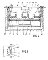
- FIG. 4 a third embodiment of the electrical installation device according to the invention is shown.
- this electrical installation device is again a safety socket. 4 differs from FIGS. 1 and 2 in that the section through the parts of the protective contact socket is offset by 90 °. As a result, the earthing bracket 20 has now become visible in FIG. 4.
- the insulating base 16 has maintained its training.
- the circuit board 23 with the acoustic signal device 24 is also not directly connected to the bottom of the insulating base 16 here, but is at a distance below it.
- 25 retaining strips 41 are attached to the inner walls of the insulating material housing. In the selected embodiment, these are present in pairs, such that they enclose a gap between them, the dimensions of which are adapted to the thickness of the board 23.
- the insulating material housing 25 has at least two fastening arms 42 on at least two diametrically opposite sides of its peripheral surface. In the exemplary embodiment, this is bent outwards from the basic plane of the peripheral surface of the insulating material housing 25, to the extent that that the mounting arm 42 comes to rest in the area of a hole 44 of the support ring 11.
- the mounting arm 42 is dimensioned so long that it can pass through a hole 44 of this support ring 11.
- the area of the fastening arm 42 protruding from the support ring plane has a holding element which is supported on the outside of the support ring.
- each fastening arm 42 projecting beyond the support ring plane is at the same time designed as a fastening end 43 which interacts with the support ring 11.
- the fastening end 43 of each fastening arm 42 of the insulating housing 45 is widened by forming a head in such a way that the width of this head projects beyond both the hole 44 and the widening 45 adjoining it.
- This training can best be seen from FIG. 5 of the drawing.
- any known acoustically operating signaling device can be used as a signaling device, insofar as its external one Dimensions are such that they can be accommodated in the gap between the board 23 and the bottom of the insulating housing 25.
- the size of this gap can still be varied by, for example, placing the bottom 36 of the insulating material housing higher than shown. In this way, the prescribed distance between the underside of the bottom 36 of the insulating material housing and the bottom of the flush-mounted box 28, not shown.
- the box - as in the exemplary embodiments - is designed as a flush-mounted box 28. Rather, it can also be a surface-mounted box or a cable box, ie one that is used in connection with cable ducts.
- the term “can” should also include box-shaped embodiments. A circular design of the can in cross section is therefore not necessary. However, this is preferred because in practice, circular designs of the flush-mounted box are generally used in cross-section. It is also advantageous that the manufacturing tools previously used for the parts of the safety socket can continue to be used. For example, this applies to the support ring.
- the removal of the expanding claws does not change anything because these expanding claws are not an integral part of the support ring but instead only grip through the opening of the retaining web with one leg, in order then to be fastened to the insulating base 16 using one screw each.
- the insulating base 16 can also have a known design. If necessary, it must still be on its underside be equipped with fasteners to hold the board in place. However, this only applies to some of the versions shown. Not, for example, for the one according to FIGS. 2 and 4 of the drawing. In the former case, the cohesion between the circuit board 23 and the insulating base 16 takes place by the force of the springs 39. In the case of the embodiment according to FIG. 4 of the drawing, the circuit board 23 is not connected directly to the insulating base at all, but to the inner wall of the insulating material housing using it of holding bars.
- the flush-mounted box 28 can also be configured differently from the one shown. In particular, it can be kept much thinner. In this case, fastening domes are to be molded onto the inner walls in order to make room for the accommodation of the blind holes 29 for receiving the retaining screws 3o.
Abstract
Description
Die Erfindung bezieht sich auf ein elektrisches Installationsgerät, insbesondere Schutzkontaktsteckdose, mit einem von einem Haltestege aufweisenden Tragring gehaltenen Isolierstoffsockel, der außer den elektrischen Kontakten, dem Erdungsbügel und mechanischen Halteelementen zusätzlich eine Platine mit Überspannungsschutzelementen aufweist, deren Wirksamkeit durch eine der Platine zugeordnete Signaleinrichtung anzeigbar ist, wobei der Tragring mit einer diese Bauteile umfassenden Aufnahmedose, wie einer Unterputzdose, verbindbar ist.The invention relates to an electrical installation device, in particular a protective contact socket, with an insulating base held by a supporting ring having supporting webs, which in addition to the electrical contacts, the earthing clip and mechanical holding elements additionally has a circuit board with surge protection elements, the effectiveness of which can be indicated by a signaling device assigned to the circuit board , wherein the support ring can be connected to a receptacle comprising these components, such as a flush-mounted box.
Elektrische Installationsgeräte dieser Art sind in zahlreichen Ausführungsformen bekannt. Sie haben an sich den Vorteil, daß sie die an die Steckdose angeschlossenen Geräte vor Überspannung schützen. Dies deshalb, weil sie im Bereich ihres Isolierstoffsockels eine Platine mit Überspannungsschutzelementen aufweisen. Diese können beim Auftreten sehr energiereicher Überspannungen zerstört werden, so daß die Schutzschaltung funktionsunfähig wird.Electrical installation devices of this type are known in numerous embodiments. They have the advantage in themselves that they protect the devices connected to the socket from overvoltage. This is because they have a circuit board with overvoltage protection elements in the area of their insulating base. These can be destroyed in the event of very high-energy overvoltages, so that the protective circuit becomes inoperative.
Es gibt dabei auch elektrische Installationsgeräte, die mit einer Signaleinrichtung ausgerüstet sind, welche dem Benutzer dieses elektrischen Installationsgerätes anzeigt, ob das Überspannungsschutzelement defekt oder noch funktionsfähig ist. An sich sind solche elektrischen Installationseinrichtungen mit einer Signaleinrichtung für den Benutzer sehr vorteilhaft, weil er von außen her erkennen kann, ob die im Inneren des Installationsgerätes liegende Überspannungsschutzeinrichtung noch funktionsfähig ist oder nicht. Auf der anderen Seite haben derartige Ausführungsformen noch Mängel. Diese sind nicht zuletzt darauf zurückzuführen, daß es bisher optisch wirkende Signaleinrichtungen gibt. Diese sind in aller Regel an einer Abdeckplatte des elektrischen Installationsgerätes angebracht. Sie bestehen meist aus zwei Lämpchen, die von einer eingefärbten Linse od.dgl. überdeckt sind. Die eine Linse ist dabei grün, die andere rot eingefärbt. Solange die Überspannungsschutzelemente im Inneren eines solchen Installationsgerätes intakt sind, leuchtet das grüne Lämpchen auf, sobald eine Zerstörung des oder der Überspannungselemente stattgefunden hat, erlischt die grüne Lampe, und es leuchtet nunmehr eine rote Lampe auf. Dies ist für den Benutzer das Zeichen, daß das Installationsgerät mit dem Überspannungsschutzelement defekt ist, und daß es mindestens teilweise ausgetauscht werden muß. Es hat sich nun gezeigt, daß derartige, optisch arbeitende Signaleinrichtungen nicht allen Anforderungen in der Praxis genügen, insbesondere dann nicht, wenn sie in sehr hellen Räumen aufgestellt sind, oder wenn sie in Räumen benutzt werden, die mit zahlreichen Anzeigelampen od.dgl. ausgerüstet sind. Im ersten Falle, nämlich bei grellem Licht, sind die optischen Signaleinrichtungen schwer für den Benutzer zu erkennen, in dem anderen Fall, wenn viele Anzeigelampen in ein und demselben Raum vorhanden sind, kann man leicht übersehen, daß die rote Lampe des Installationsgerätes aufleuchtet und anzeigt, daß das Überspannungsschutzelement defekt ist.There are also electrical installation devices which are equipped with a signal device which indicates to the user of this electrical installation device whether the overvoltage protection element is defective or still is functional. In itself, such electrical installation devices with a signal device are very advantageous for the user because he can recognize from the outside whether the surge protection device located inside the installation device is still functional or not. On the other hand, such embodiments still have shortcomings. These are not least due to the fact that there have been optical signaling devices so far. These are usually attached to a cover plate of the electrical installation device. They usually consist of two lamps or the like from a colored lens. are covered. One lens is green, the other colored red. As long as the overvoltage protection elements inside such an installation device are intact, the green lamp lights up, as soon as the overvoltage element (s) has been destroyed, the green lamp goes out and a red lamp now lights up. For the user, this is the sign that the installation device with the overvoltage protection element is defective and that it must be replaced at least in part. It has now been shown that such optically operating signal devices do not meet all the requirements in practice, especially not if they are set up in very bright rooms, or if they are used in rooms which or the like with numerous indicator lamps. are equipped. In the first case, namely in bright light, the optical signaling devices are difficult for the user to recognize, in the other case, when there are many indicator lamps in the same room, it can easily be overlooked that the red lamp of the installation device lights up and indicates that the overvoltage protection element is defective.
Es ist außerdem bekannt, daß als Signaleinrichtung eine akustische Signaleinrichtung benutzt wird. So ist aus der DE-A-38 40 198 eine Steckdose mit Überspannungsschutz mit einer akustischen Anzeige eines Defektes des Überspannungsschutzes bekannt. Diese Druckschrift bezieht sich auf eine Steckdose mit Überspannungsschutz, der an oder in den Steckdosensockel eingebaut ist, beispielsweise in Form eines am Steckdosensockel angebrachten Zusatzmoduls, wobei eine Anzeige eines Defektes des Überspannungsschutzes gegeben ist. Um einen Ausfall des Überspannungsschutzes sicher anzuzeigen, ohne daß hierzu die gezielte Aufmerksamkeit der jeweiligen Bedienungs- oder Kontrollperson verlangt wird, wird bei dieser bekannten Ausführungsform der Signaleinrichtung vorgeschlagen, daß als Anzeige eine akustische Anzeige vorgesehen ist, und daß sich die Mittel dieser akustischen Anzeige in der Steckdose bzw. am oder im Steckdosensockel befinden. Die Verwendung einer solchen akustischen Signaleinrichtung hat gegenüber den vorbekannten, optisch wirkenden Signaleinrichtungen erhebliche Vorteile. Da eine akustisch wirkende Signaleinrichtung z.B. einen Dauerton abgibt, ist es für den Benutzer einer derartigen elektrischen Steckdose praktisch unmöglich, daß er nicht darauf aufmerksam gemacht wird, daß die Überspannungsschutzeinrichtung des Installationsgerätes ausgefallen ist, und daß daher Abhilfe geschaffen werden muß. Eine solche akustische Signaleinrichtung ist sowohl in sehr hellen Räumen, aber auch in Räumen mit vielen Anzeigeeinrichtungen unüberhörbar. Dabei wird bei der bekannten Ausführungsform ein elektronischer, akustischer Signalgeber an sich bekannter Bauart vorgeschlagen, es ist aber auch vorgesehen, Signalgeber die als sogenannte Buzzer bekannt sind.It is also known that an acoustic signaling device is used as the signaling device. From DE-A-38 40 198 a socket with surge protection with an acoustic display of a defect in the surge protection is known. This document relates to a socket with overvoltage protection, which is installed on or in the socket base, for example in the form of an additional module attached to the socket base, whereby a defect in the overvoltage protection is indicated. In order to reliably indicate a failure of the overvoltage protection without requiring the specific attention of the respective operator or control person, it is proposed in this known embodiment of the signaling device that an acoustic display is provided as the display and that the means of this acoustic display are in the socket or on or in the socket base. The use of such an acoustic signal device has considerable advantages over the known optical signal devices. Since an acoustic signaling device e.g. emits a continuous tone, it is practically impossible for the user of such an electrical socket that he is not made aware that the overvoltage protection device of the installation device has failed and that remedial action must therefore be taken. Such an acoustic signal device is unmistakable not only in very bright rooms, but also in rooms with many display devices. In the known embodiment, an electronic, acoustic signal transmitter of known design is proposed, but it is also provided that signal transmitters are known as so-called buzzers.
Es hat sich nun bei dieser aus der DE-A-38 40 198 bekannten Ausführungsform des Installationsgerätes gezeigt, daß nicht alle in der Praxis auftretenden Anforderungen erfüllt werden. Insbesondere weist die bekannte Steckdose einen unzureichenden Schutz des Isolierstoffsockels der Schaltungsanordnung mit den Überspannungsschutzelementen sowie der Signaleinrichtung gegen Beschädigungen bei der Lagerung und beim Transport auf.It has now become known in this from DE-A-38 40 198 Embodiment of the installation device shown that not all requirements that occur in practice are met. In particular, the known socket has inadequate protection of the insulating base of the circuit arrangement with the overvoltage protection elements and the signaling device against damage during storage and transport.
Hier will nun die Erfindung Abhilfe schaffen. Ihr liegt die Aufgabe zugrunde, bei einem Installationsgerät mit einer Überspannungsschutzeinrichtung sowie einer Signaleinrichtung der angegebenen Art eine abgekapselte Baueinheit vorzusehen, die an vorhandenen Bauteilen des Installationsgerätes ohne separate Verbindungsmittel festgelegt werden kann.The invention now seeks to remedy this. It is based on the object of providing an encapsulated structural unit in the case of an installation device with an overvoltage protection device and a signal device of the type specified, which can be attached to existing components of the installation device without separate connecting means.
Zur Lösung dieser Aufgabe wird erfindungsgemäß vorgeschlagen, daß der Isolierstoffsockel und die Platine mit den dieser zugeordneten Bauteilen von einem Isolierstoffgehäuse umgeben ist, das an vorhandenen Aufnahmen des Tragringes der Steckdose festlegbar ist. Das erfindungsgemäß ausgebildete elektrische Installationsgerät hat gegenüber den bekannten Ausführungsformen erhebliche Vorteile, da zum einen ein geeigneter Schutz des Isolierstoffsockels der Platine mit den Überspannungsschutzelementen sowie der Signaleinrichtung gegen Beschädigungen bei der Lagerung und beim Transport gewährleistet ist. Weiterhin dienen zu ihrer Festlegung an dem Installationsgerät die ohnehin vorhandenen Aufnahmen bzw. Durchbrüche am Tragring, z.B. der Steckdose. Dadurch ist weder eine Änderung des Isolierstoffsockels noch des Tragringes des elektrischen Installationsgerätes erforderlich, so daß die vorhandenen Herstellungswerkzeuge für ein derartiges Installationsgerät weiterhin benutzt werden können.To achieve this object, it is proposed according to the invention that the insulating base and the circuit board with the components assigned to it are surrounded by an insulating housing which can be fixed on existing receptacles of the supporting ring of the socket. The electrical installation device designed according to the invention has considerable advantages over the known embodiments since, on the one hand, suitable protection of the insulating base of the circuit board with the overvoltage protection elements and the signaling device is guaranteed against damage during storage and transport. Furthermore, the already existing receptacles or openings on the support ring, for example the socket, serve to fix them on the installation device. As a result, neither a change in the insulating material base nor in the support ring of the electrical installation device is necessary, so that the existing production tools can continue to be used for such an installation device.
Damit können die Kosten für die Erstellung neuer Werkzeuge weitgehend eingespart werden. Darüber hinaus ist es auch nicht erforderlich, besondere Ausführungsformen von elektrischen Installationsgeräten zu schaffen, beispielsweise solche, die mit verkürzten Tragstegen des Tragringes arbeiten. Dabei kommt hinzu, daß normale, handelsübliche Unterputzdosen benutzt werden können, und daß diese z.B. voll in einer Wand untergebracht werden können, ohne daß ein störender Vorsprung entsteht.The costs for the creation of new tools can thus be largely saved. In addition, it is also not necessary to create special embodiments of electrical installation devices, for example those which work with shortened support webs of the support ring. In addition, normal, commercially available flush-mounted boxes can be used, and that these e.g. can be fully housed in a wall without creating an annoying projection.
Hinsichtlich der Festlegung des Isolierstoffgehäuses an den vorhandenen Teilen eines handelsüblichen elektrischen Installationsgerätes sind mehrere Ausführungsformen denkbar.With regard to the fixing of the insulating material housing to the existing parts of a commercially available electrical installation device, several embodiments are conceivable.
Nach einem ersten Vorschlag der Erfindung ist das Isolierstoffgehäuse an den Haltestegen des Tragringes des Installationsgerätes befestigt. Dabei wird eine solche Befestigung bevorzugt, bei der die üblichen Spreizkrallen der Haltestege des Tragringes entfernt werden. Die Begrenzungswandungen der für die Spreizkrallen vorgesehenen Durchbrüche dienen nunmehr als Gegenrasten für Rasten des Isolierstoffgehäuses. Das Entfernen der Spreizkrallen kann problemlos erfolgen, weil diese meist mittels einer Schraube lösbar am Sockel befestigt werden. Durch Entfernen dieser Befestigungsschraube kann man, ohne den Isolierstoffsockel verändern zu müssen, die Spreizkralle entfernen. Dadurch wird der Durchbruch in dem Haltesteg frei und kann erfindungsgemäß als Gegenraste eingesetzt werden. Durch eine derartige Gegenrast entfällt somit eine Veränderung gegenüber der bisherigen Ausbildung des Haltesteges. Mit dieser Gegenrast wirkt jeweils eine Rast des Isolierstoffgehäuses zusammen.According to a first proposal of the invention, the insulating material housing is fastened to the retaining webs of the support ring of the installation device. Such a fastening is preferred in which the usual expanding claws of the retaining webs of the support ring are removed. The boundary walls of the openings provided for the expanding claws now serve as counter-latching for latching the insulating material housing. The expansion claws can be removed without any problems because they are usually detachably attached to the base by means of a screw. By removing this fastening screw, you can remove the expansion claw without having to change the insulating base. As a result, the breakthrough in the retaining web is free and can be used as a counter-catch according to the invention. Such a counter-latching means that there is no change compared to the previous design of the retaining web. With this counter detent, a detent of the insulating material housing interacts.
Dabei empfiehlt es sich, die Seitenwandungen des Isolierstoffgehäuses auf diametral gegenüberliegenden Bereichen abgewogene Arme aufweisen zu lassen, die an ihren freien Enden jeweils eine angeformte Rast haben. Die abgebogenen Arme des Isolierstoffgehäuses können bei dessen Fertigung miterzeugt werden. Die Stärke der Abbiegung wird dabei so gewählt, daß die Haken am vorderen freien Ende der Arme im guten Wirkkontakt mit den Gegenrasten im Bereich der Durchbrüche der Haltestege kommen. Auf diese Weise entsteht mit einfachen Mitteln eine Rastverbindung, die darüber hinaus den Vorteil hat, daß sie bei Bedarf wieder gelöst werden kann.It is advisable to have the side walls of the insulating material housing weighed arms on diametrically opposite areas, each of which has a molded catch at its free ends. The bent arms of the insulating material housing can also be produced during its manufacture. The strength of the bend is chosen so that the hooks on the front free end of the arms come into good operative contact with the counter-catches in the area of the openings of the holding webs. In this way, a snap connection is created with simple means, which also has the advantage that it can be released again if necessary.
Nach einem weiteren Vorschlag der Erfindung ist dagegen das Isolierstoffgehäuse mittels Befestigungsstiften am Isolierstoffsockel festgelegt. Die einen Enden solcher Befestigungsstifte sind mit Haltevorsprüngen ausgerüstet; diese durchgreifen jeweils einen Durchbruch des abgewinkelten Endes des Haltesteges, nachdem sie vorher durch einen sowieso vorhandenen Durchbruch des Sockels hindurchgesteckt sind. Die Haltevorsprünge wirken dann mit den Begrenzungswandungen des Durchbruches des abgewinkelten Endes des Haltesteges im Sinne einer Festhaltung zusammen. Das gegenüberliegende andere Ende jedes Befestigungsstiftes durchgreift dagegen den Boden des Isolierstoffgehäuses und wird an der Außenseite des Bodens festgelegt. Dies kann beispielsweise durch ein Sicherungselement, wie eine Sicherungsscheibe, erfolgen.According to a further proposal of the invention, however, the insulating material housing is fixed on the insulating base by means of fastening pins. The one ends of such fastening pins are equipped with retaining projections; these each penetrate an opening in the angled end of the retaining web after they have previously been inserted through an already existing opening in the base. The holding projections then interact with the boundary walls of the opening of the angled end of the holding web in the sense of a retention. The opposite other end of each fastening pin, however, passes through the bottom of the insulating material housing and is fixed on the outside of the bottom. This can be done, for example, by a locking element, such as a locking washer.
Es empfiehlt sich, jeden Befestigungsstift an seinem dem Isolierstoffsockel zugekehrten Ende, an seiner Umfangsfläche in Achsrichtung hintereinanderliegend, mehrere, vorzugsweise regelmäßig angeordnete und untereinander gleichgestaltete Haltevorsprünge aufweisen zu lassen. Von diesen Haltevorsprüngen kommt dann jeweils einer mit den erwähnten Begrenzungswandungen des Durchbruches des abgewinkelten Endes des Haltesteges in Wirkverbindung. Auf diese Weise kann man beispielsweise eine Anpassung am Isolierstoffsockel mit unterschiedlicher Höhe erreichen.It is advisable to have each fastening pin at its end facing the insulating material base, one behind the other on its circumferential surface in the axial direction, several, preferably regularly arranged and mutually identical retaining projections. Of each of these retaining projections then comes into operative connection with the boundary walls of the opening of the angled end of the retaining web mentioned. In this way, for example, an adaptation to the insulating base with different heights can be achieved.
Bei der bevorzugten Ausführungsform der Erfindung durchgreift das untere Ende jedes Befestigungsstiftes zur Ermöglichung einer Veränderung Ihres gegenseitigen Abstandes je ein Langloch im Boden des Isolierstoffgehäuses. Diese Langlöcher ermöglichen es somit, den gegenseitigen Abstand der beiden vorhandenen Befestigungsstifte zu vergrößern oder zu verkleinern, natürlich nur, soweit es die Länge der Langlöcher zuläßt.In the preferred embodiment of the invention, the lower end of each fastening pin passes through an elongated hole in the bottom of the insulating material housing in order to enable a change in their mutual distance. These elongated holes thus make it possible to increase or decrease the mutual distance between the two existing fastening pins, of course only to the extent that the length of the elongated holes permits.
Bei der bevorzugten Ausführungsform der Erfindung wird der untere, von den Haltevorsprüngen freie Teil jedes Befestigungsstiftes von einer Feder umgeben. Diese stützt sich mit ihrem einen Ende an der Innenfläche des Bodens des Isolierstoffgehäuses ab, während ihr anderes Ende gegebenenfalls unter Zwischenschaltung einer Unterlegscheibe gegen die Platine drückt, welche die Überspannungsschutzelemente und die akustisch wirkende Signaleinrichtung trägt. Auf diese Weise kann auf eine besondere Verbindung zwischen der erwähnten Platine und dem Isolierstoffsockel verzichtet werden. Vielmehr dienen die beiden vorhandenen Federn der beiden Befestigungsstifte zugleich zum Andrücken dieser Platine gegen die Unterseite des Isolierstoffsockels.In the preferred embodiment of the invention, the lower part of each fastening pin, free of the holding projections, is surrounded by a spring. This is supported at one end on the inner surface of the bottom of the insulating material housing, while its other end presses against the circuit board, optionally with the interposition of a washer, which carries the overvoltage protection elements and the acoustically acting signaling device. In this way, a special connection between the mentioned board and the insulating base can be dispensed with. Rather, the two existing springs of the two fastening pins also serve to press this board against the underside of the insulating base.
Bei einer dritten Ausführungsform der Erfindung weist das Isolierstoffgehäuse wenigstens an zwei diametral gegenüberliegenden Seiten seiner Umfangsfläche je einen Befestigungsarm auf, der je eines der im Tragring vorhandenen Löcher durchgreift. Der nach dem Durchgreifen aus der Tragringebene herausragende Bereich des Befestigungsarmes weist ein sich an der Außenseite des Tragringes abstützendes Halteelement auf. Dieses Halteelement kann unterschiedlich gestaltet und ausgebildet sein. Es kann sich dabei um ein separates Halteelement handeln, welches z.B. einen Durchbruch des aus der Tragringebene vorstehenden Teiles des Befestigungsarmes durchgreift und sich quer über die Begrenzungsränder des jeweiligen Loches des Tragringes legt. Auf diese Weise wird eine Zurückbewegung des Befestigungsarmes vermieden.In a third embodiment of the invention, the insulating material housing has at least on two diametrically opposite sides of its circumferential surface a fastening arm, each of which is present in the support ring Reaches through holes. The area of the fastening arm which projects out of the supporting ring plane after reaching through has a holding element which is supported on the outside of the supporting ring. This holding element can be designed and designed differently. It can be a separate holding element which, for example, penetrates an opening in the part of the fastening arm projecting from the support ring plane and lies transversely over the boundary edges of the respective hole in the support ring. In this way, a return movement of the mounting arm is avoided.
Bevorzugt wird jedoch eine Ausführungsform, bei der das die Tragringebene überragende Ende des Befestigungsarmes jeweils zugleich als mit dem Tragring zusammenwirkendes Befestigungselement ausgebildet ist. In einem solchen Falle wird das Befestigungsende jedes Befestigungsarmes des Isolierstoffgehäuses zweckmäßig durch Kopfbildung verbreitert, derart, daß dieser Kopf breitenmäßig sowohl das Loch des Tragringes als auch die sich daran anschließende Verbreiterung desselben überragt.However, an embodiment is preferred in which the end of the fastening arm projecting beyond the support ring plane is at the same time designed as a fastening element which interacts with the support ring. In such a case, the fastening end of each fastening arm of the insulating material housing is expediently widened by forming a head in such a way that the width of this head projects beyond both the hole in the supporting ring and the widening thereof that follows.
Bei einer abgewandelten Ausführungsform der Erfindung hat das Isolierstoffgehäuse an seiner Innenwand unterhalb des Bodens des Isolierstoffsockels liegend Halteleisten für die Platine der Überspannungsschutzelemente bzw. der akustischen Signaleinrichtung. Es können dabei paarweise angeordnete Halteleisten vorhanden sein, die einen der Dicke der Platine entsprechenden gegenseitigen Abstand voneinander haben. Auf diese Weise kann man in den zwischen den paarweise angeordneten Halteleisten vorhandenen Spalt das Ende der Platine einschieben und es lagesichern.In a modified embodiment of the invention, the insulating material housing has holding strips for the circuit board of the overvoltage protection elements or the acoustic signal device lying on its inner wall below the bottom of the insulating material base. There can be holding strips arranged in pairs, which have a mutual spacing corresponding to the thickness of the board. In this way, the end of the circuit board can be inserted into the gap between the retaining strips arranged in pairs and secured in position.
In den Figuren der Zeichnungen ist die Erfindung in mehreren Ausführungsbeispielen dargestellt, und zwar zeigen:
- Fig. 1
- einen Längsschnitt durch eine erste Ausführungsform eines erfindungsgemäß ausgebildeten elektrischen Installationsgegerätes in Form einer Schutzkontaktsteckdose;
- Fig. 2
- ebenfalls im Längsschnitt eine zweite Ausführungsform eines erfindungsgemäß ausgebildeten elektrischen Installationsgerätes;
- Fig. 3
- einen Teilschnitt entlang der Linie III - III der Fig. 2, teilweise weggebrochen;
- Fig. 4
- eine dritte Ausführungsform eines erfindungsgemäß ausgebildeten elektrischen Installationsgerätes im Längsschnitt, jedoch im Bezug auf die Ausführungsform nach den Fig. 1 und 2 der Zeichnung um 90° gedreht, und
- Fig. 5
- teilweise weggebrochen eine Draufsicht auf einen Teilbereich des elektrischen Installationsgerätes gemäß der Fig. 4 der Zeichnung.
- Fig. 1
- a longitudinal section through a first embodiment of an electrical installation device designed according to the invention in the form of a safety socket;
- Fig. 2
- likewise in longitudinal section, a second embodiment of an electrical installation device designed according to the invention;
- Fig. 3
- a partial section along the line III - III of Figure 2, partially broken away.
- Fig. 4
- a third embodiment of an electrical installation device designed according to the invention in longitudinal section, but rotated by 90 ° with respect to the embodiment of FIGS. 1 and 2 of the drawing, and
- Fig. 5
- partially broken away a plan view of a portion of the electrical installation device according to FIG. 4 of the drawing.
Es sei zunächst erwähnt, daß in den Figuren der Zeichnungen nur diejenigen Teile eines elektrischen Installationsgerätes dargestellt sind, welche für das Verständnis der Erfindung Bedeutung haben. So fehlen beispielsweise auf dem Isolierstoffsockel des Installationsgerätes die Anschlußkontakte und die dazugehörigen Leitungen. Es fehlen ferner die der Platine zugeordneten Teile, nämlich die Überspannungsschutzelemente. Die Signaleinrichtung ist nur schematisch wiedergegeben. Dies deshalb, weil alle in den Figuren der Zeichnungen nicht dargestellten Teile eine bekannte Ausbildung aufweisen können, so daß auf ihre zeichnerische Darstellung weitgehend verzichtet ist.It should first be mentioned that only those parts of an electrical installation device are shown in the figures of the drawings which are important for understanding the invention. For example, the contacts and the associated cables are missing on the insulating base of the installation device. The parts assigned to the circuit board, namely the overvoltage protection elements, are also missing. The signaling device is only shown schematically. This is because all parts not shown in the figures of the drawings can have a known design, so that their graphic representation is largely dispensed with.
In der Fig. 1 der Zeichnung ist eine erste Ausführungsform des erfindungsgemäßen elektrischen Installationsgerätes wiedergegeben, und zwar in Gestalt einer generell mit 10 bezeichneten Schutzkontaktsteckdose. Zu dieser Schutzkontaktsteckdose 10 gehört ein aus einem metallischen Werkstoff hergestellter einstückiger Tragring 11, der an zwei diametral gegenüberliegenden Seiten etwa rechtwinklig abgebogene Haltestege 12 aufweist; diese gehen in ein mit 14 bezeichnetes abgewinkeltes Ende über. mit seiner Außenseite liegt das abgewinkelte Ende 14 auf der zugekehrten Fläche eines grundsätzlich bekannten Isolierstoffsockels 16. Zur Herstellung der Verbindung zwischen dem Tragring 11 und dem Isolierstoffsockel 16 dienen Befestigungsschrauben 15, die einen Durchbruch 35 im abgewinkelten Ende 14 des Haltesteges 12 durchgreifen und mit ihrem Schaft in einer Sacklochbohrung des Isolierstoffsockels 16 enden.1 of the drawing shows a first embodiment of the electrical installation device according to the invention, namely in the form of a protective contact socket generally designated 10. This
Bei dem Tragring 11 handelt es sich um eine handelsübliche Ausführungsform, die sich jedoch von dieser dadurch insoweit unterscheidet, als die an sich vorhandenen Spreizkrallen entfernt worden sind. Diese Spreizkrallen durchgreifen normalerweise mit ihrem rückwärtigen Ende einen Durchbruch 13 in dem Haltesteg 12, wobei das rückwärtige Ende mit einer Schraube zusammenwirken kann, derart, daß beim Betätigen der Schraube die Spreizkralle nach außen bewegt wird, um mit ihrer spitzen Kralle mit der Außenfläche einer Dose, beispielsweise einer Unterputzdose, in Wirkverbindung treten zu können. Diese Spreizkralle und die ihr zugeordnete Befestigungsschraube sind bei der Ausführungsform des Tragringes nach der Fig. 1 fortgelassen. Soweit es die Bohrung für die Schraube der Spreizkralle angeht, wird diese nun zur Unterbringung der Befestigungsschraube 15 herangezogen. Es braucht daher insoweit zur Unterbringung für den Schraubenschaft keine besondere Sacklochbohrung geschaffen werden, weil diese bereits vorhanden ist. Der Durchbruch 13 des Haltesteges wird ebenfalls in üblicher Ausführung benutzt. Er hat jedoch nunmehr eine andere Funktion. Er dient nämlich mit seinen Begrenzungswandungen als Gegenrast für die Aufnahme einer Rast 27, die Bestandteil eines generell mit 25 bezeichneten Isolierstoffgehäuses ist. Diese Rast 27 sitzt am Ende eines abgebogenen Armes 26 des Isolierstoffgehäuses 25. Im gewählten Ausführungsbeispiel sind an den Seitenwandungen des Isolierstoffgehäuses 25 an zwei diametral gegenüberliegenden Seiten die Arme 26 vorgesehen, die um etwa 45° aus der Ebene der Seitenwand abgebogen sind, und die an ihrem vorderen freien Ende je eine Rast 27 tragen, die den Durchbruch 13 des Haltesteges 12 in der in Fig. 1 dargestellten Weise durchgreift und dabei mit den Gegenrasten des Haltesteges 12 zusammenwirkt, die wie gesagt durch die Begrenzungswandungen dieses Durchbruches 13 gebildet sind.The
Der Isolierstoffsockel 16 hat ebenfalls eine handelsübliche Ausbildung. Er wird einstückig aus einem der in der Elektroindustrie gebräuchlichen Isolierstoffe hergestellt; er dient u.a. zum Unterbringen der Anschlußkontakte und des Erdungsbügels. Von den von dem Isolierstoffsockel 16 getragenen elektrischen Einrichtungen sind nur einige dargestellt. So sind aus der Ebene des Isolierstoffsockels in Richtung auf den Tragring 11 zeigend hochgezogene Wandungen 17 vorgesehen, die Aufnahmen begrenzen. Da ist zunächst die Aufnahme 18, die zur Unterbringung der nicht dargestellten Anschlußkontakte dient. Diese Anschlußkontakte umfassen auch die federnden Teile, die zum Eingriff des nicht dargestellten Steckers herangezogen werden.The insulating
Die in der Mitte des Isolierstoffsockels 16 liegende Aufnahme ist mit 19 bezeichnet; diese dient zur Unterbringung eines Erdungsbügels 20, der in aller Regel mit einem nicht dargestellten Niet in seiner Mitte fest mit dem Isolierstoffsockel 16 verbunden wird. Rechts und links des Steges des Erdungsbügels 20 sind die Erdungsschrauben 21 angebracht von denen in der Fig. 1 lediglich die eine dargestellt ist. Die Verbindungsleitungen auf dem Sockel fehlen.The receptacle lying in the middle of the insulating
Unterhalb des Sockels 16 ist eine Platine 23 angeordnet, die in ihren Längenabmessungen etwa denjenigen des Isolierstoffsockels 16 entspricht, diese dient zur Lagerung von Überspannungsschutzelementen. Diese Überspannungsschutzelemente, die auf der Platine 23 angebracht sind, haben eine grundsätzlich bekannte Ausbildung. Ihr Verwendungszweck ist ebenfalls bekannt, so daß weitgehend auf ihre zeichnerische Darstellung verzichtet ist.A
Erfindungsgemäß ist nun dieser Platine 23 eine mit 24 bezeichnete akustische Signaleinrichtung zugeordnet, die schematisch dargestellt ist, da sie ebenfalls in ihrem Aufbau grundsätzlich bekannt ist. Beispielsweise kann es sich um elektronische, akustische Signalgeber handeln, die unter der Bezeichnung Buzzer bekannt sind.According to the invention, this
Die Platine 23 kann mit grundsätzlich bekannten Befestigungsmitteln mit den Innenwandungen des Isolierstoffgehäuses 25 im Abstand zum Isolierstoffsockel 16 verbunden werden; erwähnt seien beispielsweise Klammerverbindungen, Klebverbindungen, Rastverbindungen od.dgl. Die Befestigung kann zur Lagesicherung der Platine 23 durch an den Innenwandungen des Isolierstoffgehäuses 25 angeordnete Halteleisten 41 erfolgen, welche die Platine 23 am Rand bereichsweise umfassen. Diese Halteleisten 41 sind demnach beispielsweise paarweise vorhanden, derart, daß sie einen Spalt zwischen sich einschließen, dessen Weite der Dicke der Platine angepaßt ist.The
Wie schon erwähnt, ist im gewählten Ausführungsbeispiel das mit 25 bezeichnete Isolierstoffgehäuse ein im Querschnitt gesehen etwa U-förmiger Körper, dessen Boden 36 den Steg dieses U's bildet. Die Seitenwandungen, die dem Schenkel des U's entsprechen, sind im Ausführungsbeispiel nach der Fig. 1 etwa bis zur Höhe der Unterseite des Tragringes 11 hochgezogen. Bei dieser Ausführungsform werden somit alle auf dem Isolierstoffsockel 16 befindlichen Teile von dem Isolierstoffgehäuse 25 umgeben. Es sind lediglich Bereiche freigelassen, in denen die abgebogenen Arme 26 liegen.As already mentioned, in the selected exemplary embodiment, the insulating material housing designated by 25 is an approximately U-shaped body when viewed in cross section, the bottom 36 of which forms the web of this U. The side walls, which correspond to the leg of the U's, are raised in the exemplary embodiment according to FIG. 1 approximately to the level of the underside of the
Der horizontal liegende Bereich des Tragringes 11 ist in grundsätzlich bekannter Weise mit insgesamt vier Löchern 44 versehen; von diesen ist eines in der Fig. 5 der Zeichnung wiedergegeben. Daraus ergibt sich, daß jedes Loch 44 gekrümmte Begrenzungswandungen aufweist, und daß das Loch 44 an seinem einen Ende in eine in Draufsicht gesehen kreisförmige Erweiterung 45 übergeht. Ein solches Loch 44 des Tragringes 11 kann nun benutzt werden, um diesen Tragring mit einer Dose 28 zu verbinden, die im Ausführungsbeispiel nach der Fig. 1 der Zeichnung als Unterputzdose ausgebildet ist. Die Verbindung zwischen dem Tragring 11 und der Unterputzdose 28 erfolgt mittels Halteschrauben 30, die zwei diametral gegenüberliegende Löcher 44 des Tragringes durchgreifen und mit ihrem Schaft jeweils in ein Sackloch 29 der Unterputzdose 46 eingreifen. Im Ausführungsbeispiel nach der Fig. 1 der Zeichnung hat die Unterputzdose 28 eine so große Wandstärke, daß man die Sacklöcher 29 ohne weiteres in ihnen unterbringen kann, wie die Zeichnung wiedergibt. Es ist aber bei Bedarf auch möglich, anstelle derartiger Unterputzdosen dünnwandige einzusetzen. Um in diesem Falle Unterbringungsräume für die Schäfte der Halteschrauben 30 zu schaffen, werden Dome benutzt, die ihrerseits die Sacklöcher 29 aufnehmen. Dabei ist es möglich, diese Dome sowohl an der Außen- als auch der Innenseite der Seitenwandung der Unterputzdose anzuformen.The horizontally lying area of the
Es ist in der Fig. 1 darauf verzichtet, die Wand mit einzuzeichnen, die einen Durchbruch aufweist, in welcher die Unterputzdose 28 untergebracht wird. Dies kann in bekannter Weise geschehen. Darüber hinaus braucht es sich bei der Dose 28 keineswegs immer um eine Unterputzdose zu handeln, vielmehr ist es auch möglich, hierfür eine Aufputzdose zu benutzen. Daneben können aber auch solche Dosen Verwendung finden, die in Verbindung mit Kabelkanälen od.dgl. zum Einsatz kommen. Auch die kastenartige Ausbildung des Aufnahmeraumes für das Isolierstoffgehäuse 25 und die in dessen Innern liegenden Teile ist denkbar. Wichtig ist nur, daß dem erfindungsgemäßen elektrischen Installationsgerät eine akustische Signaleinrichtung 24 zugeordnet ist, die beim Auftreten von Überspannungen und der dadurch erfolgenden Zerstörung von Überspannungsschutzelementen ein akustisches Signal abgibt, das für den Benutzer nicht zu überhören ist, und durch welches angezeigt wird, daß eine Unwirksamkeit der Schutzelemente der Platine vorliegt. Der Benutzer kann dann entsprechend reagieren und beispielsweise einen Austausch der Platine oder des ganzen Sockels vornehmen.It is not shown in FIG. 1 to draw in the wall which has an opening in which the flush-mounted
In den Fig. 2 und 3 der Zeichnungen ist eine zweite Ausführungsform des erfindungsgemäßen elektrischen Installationsgerätes dargestellt; diese ist wiederum als Schutzkontaktsteckdose 10 ausgebildet. Was die Ausbildung des Isolierstoffsockels und die der Dose 28 angeht, so sind keine Veränderungen vorgenommen. Insoweit kann auf die Figurenbeschreibung zu Fig. 1 verwiesen werden. Geändert hat sich jedoch die Befestigung des Isolierstoffgehäuses 25 mit dem Isolierstoffsockel 16. Dazu gilt folgendes: Nach wie vor wird der Isolierstoffsockel 16 wiederum von dem Tragring 11 gehalten, und zwar unter Benutzung der Haltestege 12. Die in den Haltestegen 12 vorhandenen Durchbrüche 13 sind bei dieser Ausführungsform ohne Bedeutung. Die Spreizkrallen sind jedoch auch bei diesem Ausführungsbeispiel entfernt, weil sie nicht zur Herstellung einer Verbindung zwischen dem Tragring und der Innenwand der Dose 28 benutzt werden. Stattdessen wird der Tragring 11 wiederum über die Halteschrauben 30 mit der Dose 28 verbunden.2 and 3 of the drawings, a second embodiment of the electrical installation device according to the invention is shown; this in turn is designed as a
Das abgewinkelte Ende 14 jedes Haltesteges ist mit einem Durchbruch 33 versehen, der jedoch nicht mehr, wie bei dem ersten Ausführungsbeispiel, mit einer Befestigungsschraube 15 zusammenwirkt, sondern nunmehr mit dem oberen Teil eines generell mit 31 bezeichneten Befestigungsstiftes. Dieser Befestigungsstift 31 hat an der Umfangsfläche seines oberen Teiles liegend mehrere Haltevorsprünge 32, die umlaufend angeordnet sind und in regelmäßiger Anordnung in Längsrichtung des Befestigungsstiftes 31 hintereinanderliegend angeordnet sind. Die Haltevorsprünge 32 haben untereinander eine gleiche Ausbildung, was die Herstellung erleichtert. Von diesen Haltevorsprüngen 32 wirkt einer mit den Begrenzungswandungen des Durchbruches 33 des abgewinkelten Endes 14 des Haltesteges 12 des Tragringes 11 zusammen. Auf diese Weise wird eine Verbindung zwischen dem Befestigungsstift 31 und dem Isolierstoffsockel 16 hergestellt. Der Befestigungsstift 31 durchgreift dabei auch eine nicht näher bezeichnete Bohrung in dem Isolierstoffsockel 16 und zum anderen auch eine ebenfalls nicht bezeichnete Bohrung der Platine 23. Das untere Ende des Befestigungsstiftes 31 ist frei von Haltevorsprüngen 32, es ist somit glattwandig gehalten. Der Befestigungsstift durchgreift mit seinem unteren Ende 35 Langlöcher 37, die im Boden 36 des Isolierstoffgehäuses 35 vorgesehen sind. Auf das durch das Langloch 37 hindurchragende Ende 35 des Befestigungsstiftes 31 wird eine Sicherungsscheibe 38 gebracht, die die Abmessungen des Langloches 37 überschreitet und sich daher sperrend gegen die Außenseite des Bodens 36 des Isolierstoffgehäuses legen kann.The
Das untere Ende 35 des Befestigungsstiftes 31 wird ferner von einer generell mit 39 bezeichneten Feder umgeben, die als Druckfeder ausgebildet ist, das heißt, das untere Ende 35 des Befestigungsstiftes 31 liegt in dem Innenraum dieser Feder 39. Das eine Ende der Feder 39 stützt sich dabei auf der Innenseite des Bodens 36 des Isolierstoffgehäuses ab, das andere Ende dagegen an einer Unterlegscheibe 34, die ihrerseits an der Unterseite der Platine 23 anliegt. Unter Vermittlung der Federn 39, die am Boden 36 ein Widerlager finden, erfolgt über die Unterlegscheibe 34 ein Andrücken der Platine 23 und damit der akustischen Signaleinrichtung 24 an die Außenseite des Isolierstoffsockels 16.The
In der Fig. 3 der Zeichnung ist die Ausbildung eines der Langlöcher 37 zu erkennen, die von dem Befestigungsstift 31 durchgriffen werden. Durch die Verwendung der Langlöcher 37 kann der gegenseitige Abstand der beiden vorhandenen Befestigungsstifte 31 variiert werden. Im Ausführungsbeispiel nach der Fig. 2 der Zeichnung haben die beiden Befestigungsstifte etwa ihren kleinsten gegenseitigen Abstand. Dieser kann dadurch vergrößert werden, daß man die Befestigungsstifte 31 in dem Langloch 37 nach unterschiedlichen Seiten auseinanderbewegt, bis die Umfangsfläche des Befestigungsstiftes an der Begrenzungskante der Langlöcher 37 anschlägt.In Fig. 3 of the drawing, the formation of one of the
Aus der Fig. 2 ist ferner erkennbar, daß bei dieser Ausführungsform das Isolierstoffgehäuse 25 in seinen Längenabmessungen wesentlich kleiner gehalten ist. Die Seitenwandungen des Isolierstoffgehäuses ragen nur etwa bis zur Höhe des unteren abgewinkelten Endes 14 des Haltesteges 12. Die Umfangsfläche des Isolierstoffgehäuses kann durchlaufend gehalten sein; durchbrochen ist in diesem Falle lediglich der Boden 36, und zwar durch die beiden in Abstand voneinander liegenden Langlöcher 37.From Fig. 2 it can also be seen that in this embodiment the insulating
In den Fig. 4 und 5 der Zeichnungen ist eine dritte Ausführungsform des erfindungsgemäßen elektrischen Installationsgerätes wiedergegeben. Bei diesem elektrischen Installationsgerät handelt es sich wieder um eine Schutzkontaktsteckdose. Die Fig. 4 unterscheidet sich von den Fig. 1 und 2 insoweit, als der Schnitt durch die Teile der Schutzkontaktsteckdose um 90° versetzt ist. Dadurch ist in der Fig. 4 nunmehr der Erdungsbügel 20 sichtbar geworden.4 and 5 of the drawings, a third embodiment of the electrical installation device according to the invention is shown. With this electrical installation device is again a safety socket. 4 differs from FIGS. 1 and 2 in that the section through the parts of the protective contact socket is offset by 90 °. As a result, the earthing
Der Isolierstoffsockel 16 hat seine Ausbildung beibehalten. Die Platine 23 mit der akustischen Signaleinrichtung 24 ist auch hier nicht unmittelbar mit dem Boden des Isolierstoffsockels 16 verbunden, sondern liegt mit Abstand darunter. Um dabei eine Lagesicherung der Platine 23 zu erzielen, sind an den Innenwandungen des Isolierstoffgehäuses 25 Halteleisten 41 angebracht. Im gewählten Ausführungsbeispiel sind diese paarweise vorhanden, derart, daß sie einen Spalt zwischen sich einschließen, dessen Abmessung der Dicke der Platine 23 angepaßt sind.The insulating
Gemäß dem Ausführungsbeispiel der Schutzkontaktsteckdose nach der Fig. 4 der Zeichnung hat das Isolierstoffgehäuse 25 wenigstens an zwei diametral gegenüberliegenden Seiten seiner Umfangsfläche je einen Befestigungsarm 42. Dieser ist im Ausführungsbeispiel aus der Grundebene der Umfangsfläche des Isolierstoffgehäuses 25 nach außen hin abgebogen und zwar so weit, daß der Befestigungsarm 42 jeweils in den Bereich eines Loches 44 des Tragringes 11 zu liegen kommt. Der Befestigungsarm 42 ist dabei so lang bemessen, daß er jeweils ein Loch 44 dieses Tragringes 11 durchgreifen kann. Der aus der Tragringebene herausragende Bereich des Befestigungsarmes 42 weist ein sich an der Außenseite des Tragringes abstützendes Halteelement auf. Im gewählten Ausführungsbeispiel ist das die Tragringebene überragende Ende jedes Befestigungsarmes 42 jeweils zugleich als mit dem Tragring 11 zusammenwirkendes Befestigungsende 43 ausgebildet. Dabei ist das Befestigungsende 43 jedes Befestigungsarmes 42 des Isolierstoffgehäuses 45 durch Kopfbildung verbreitert, derart, daß dieser Kopf breitenmäßig sowohl das Loch 44 als auch die sich daran anschließende Verbreiterung 45 desselben überragt. Diese Ausbildung ist am besten aus der Fig. 5 der Zeichnung zu erkennen. Bei dieser Ausgestaltung des Befestigungsendes 43 des Befestigungsarmes 42 kann somit auf zusätzliche Halteelemente verzichtet werden, die mit dem Tragring 11 in Verbindung treten. Gewünschtenfalls können aber auch separat hergestellte Halteelemente Verwendung finden. Diese müssen dann z.B. mit einem Durchbruch des aus der Tragringebene vorstehenden Endes des Befestigungsarmes 42 zusammenwirken und derart bemessen sein. daß sie die Abmessungen des Loches 44 bzw. der Erweiterung 45 übersteigen und sich daher auf der Außenseite des Tragringes 11 abstützen können.According to the exemplary embodiment of the protective contact socket according to FIG. 4 of the drawing, the insulating
Wie bereits erwähnt, sind die dargestellten Ausführungen nur beispielsweise Verwirklichungen der Erfindung und diese nicht darauf beschränkt. Vielmehr sind noch mancherlei andere Ausführungen und Anwendungen möglich. So kann insbesondere als Signaleinrichtung jede bekannte akustisch arbeitende Signaleinrichtung eingesetzt werden, soweit ihre äußeren Abmessungen derart beschaffen sind, daß sie in den Spalt zwischen der Platine 23 und den Boden des Isolierstoffgehäuses 25 untergebracht werden können. Die Größe dieses Spaltes läßt sich dadurch noch variieren, indem man beispielsweise den Boden 36 des Isolierstoffgehäuses höher legt als dargestellt. Auf diese Weise läßt sich der vorgeschriebene Abstand zwischen der Unterseite des Bodens 36 des Isolierstoffgehäuses und dem nicht bezeichneten Boden der Unterputzdose 28 einhalten.As already mentioned, the illustrated embodiments are only examples of implementations of the invention and are not limited to them. Rather, there are many other designs and applications possible. In particular, any known acoustically operating signaling device can be used as a signaling device, insofar as its external one Dimensions are such that they can be accommodated in the gap between the
Wie schon erwähnt, ist es für die Erfindung nicht erforderlich, daß die Dose - wie in den Ausführungsbeispielen - als Unterputzdose 28 ausgebildet ist. Vielmehr kann es sich auch um eine Aufputzdose oder auch um eine Kabeldose handeln, also um eine solche, die in Verbindung mit Kabelkanälen Verwendung findet. Unter dem Begriff "Dose" sollen im übrigen auch kastenförmige Ausführungsformen fallen. Eine im Querschnitt kreisrunde Ausbildung der Dose ist somit nicht erforderlich. Allerdings wird dieser der Vorzug deshalb gegeben, weil in der Praxis in aller Regel im Querschnitt kreisrunde Ausführungsformen der Unterputzdose Verwendung finden. Von Vorteil ist auch daß die bisher benutzten Herstellungswerkzeuge für die Teile der Schutzkontaktsteckdose weiter verwendet werden können. Beispielsweise gilt dies für den Tragring. Durch das Entfernen der Spreizkrallen ändert sich daran nichts, weil diese Spreizkrallen kein fester Bestandteil des Tragringes sind sondern mit ihrem einen Schenkel lediglich den Durchbruch des Haltesteges durchgreifen, um dann unter Benutzung je einer Schraube am Isolierstoffsockel 16 befestigt zu werden. Der Isolierstoffsockel 16 kann ebenfalls eine bekannte Ausbildung haben. Er muß gegebenenfalls noch an seiner Unterseite durch Verbindungselemente zum Festhalten der Platine ausgerüstet werden. Allerdings gilt dies nur für einige der dargestellten Ausführungen. Nicht z.B. für diejenige nach den Fig. 2 und 4 der Zeichnung. Im erstgenannten Falle erfolgt der Zusammenhalt zwischen der Platine 23 und dem Isolierstoffsockel 16 durch Krafteinwirkung der Federn 39. Im Falle der Ausführungsform nach der Fig. 4 der Zeichnung wird die Platine 23 überhaupt nicht unmittelbar mit dem Isolierstoffsockel verbunden sondern mit der Innenwand des Isolierstoffgehäuses unter Benutzung von Halteleisten.As already mentioned, it is not necessary for the invention that the box - as in the exemplary embodiments - is designed as a flush-mounted
Die Unterputzdose 28 kann auch eine andere als die dargestellte Ausbildung erhalten. Insbesondere kann sie wesentlich dünnwandiger gehalten werden. In diesem Falle sind Befestigungsdome den Innenwandungen anzuformen, um Platz zu schaffen für die Unterbringung der Sacklöcher 29 zur Aufnahme der Halteschrauben 3o.The flush-mounted
- 10 Schutzkontaktsteckdose (= elektrisches Installationsgerät)10 safety socket (= electrical installation device)
- 11 Tragring11 support ring
- 12 Haltering (an 11)12 retaining ring (on 11)
- 13 Durchbruch (in 11)13 breakthrough (in 11)
- 14 abgewinkeltes Ende14 angled end
- 15 Befestigungsschraube15 fastening screw
- 16 Isolierstoffsockel16 insulating base
- 17 hochgezogene Wandungen (an 16)17 raised walls (on 16)
- 18 Aufnahme (für Anschlußkontakte)18 receptacle (for connection contacts)
- 19 Aufnahme (für Erdungsbügel)19 holder (for earthing bracket)
- 20 Erdungsbügel20 earthing brackets
- 21 Erdungsschrauben21 grounding screws
- 22 Unterseite (von 16)22 bottom (of 16)
- 23 Platine23 circuit board
- 24 akustische Signaleinrichtung24 acoustic signaling device
- 25 Isolierstoffgehäuse25 insulating housing
- 26 abgebogener Arm (von 25)26 bent arm (of 25)
- 27 Rast27 rest
- 28 Dose = Unterputzdose28 box = flush-mounted box
- 29 Sackloch (in 28)29 blind hole (in 28)
- 30 Halteschraube30 retaining screw
- 31 Befestigungsstift31 mounting pin
- 32 Haltevorsprünge32 retaining tabs
- 33 Durchbruch (von 14)33 breakthrough (of 14)
- 34 Unterlegscheibe34 washer
- 35 unteres Ende (von 31)35 lower end (of 31)
- 36 Boden (von 25)36 floors (of 25)
- 37 Langloch (in 36)37 slot (in 36)
- 38 Sicherungsscheibe38 lock washer
- 39 Feder (von 31)39 spring (of 31)
- 40 Enden (von 23)40 ends (of 23)
- 41 Halteleiste41 retaining strip
- 42 Befestigungsarm (von 25)42 mounting arm (of 25)
- 43 Befestigungsende (von 42)43 fastening ends (of 42)
- 44 Loch (in 11)44 holes (in 11)
- 45 Erweiterung (von 44)45 expansion (of 44)
Claims (12)
- An electrical installation apparatus, in particular a safety socket, with an insulation base (16) held by a support ring (11) exhibiting holding stays (12), said base having, apart from the electric contacts, the earthing bracket and mechanical holding elements, a plate (23) with overvoltage protection elements whose effectiveness can be indicated by means of a signal facility allocated to the plate (23), the support ring (11) being connectable to a receiving socket, such as a flush-type socket, enclosing these components,
characterised in that
the insulation base (16) and the plate (23) with the components belonging to it are enclosed by an insulation housing (25) which can be secured on holders (13,33,44) provided on the support ring (11) of the electrical installation apparatus. - An installation apparatus according to claim 1, characterised in that the insulation housing (25) is attached to the holding stays (12) of the support ring (11) of the installation apparatus (10).
- An installation apparatus according to claims 1 and 2, characterised in that the limiting walls of the openings (13) provided for the removed spreader claws of the holding stays (12) of the support ring (11) can be used as mating catches for catches (27) of the insulation housing (25) (Fig. 1).
- An installation apparatus according to claims 1 to 3, characterised in that the side walls of the insulation housing exhibit bent arms (26) on diametrically opposite sections, each of said arms having a moulded catch (27) on its free end (Fig. 1).
- An installation apparatus according to claim 1, characterised in that the insulation housing (25) can be fixed to the insulation base (16) with attachment pins (31) each of which passes through an opening (33) of the angled end (14) of the holding stay (12) with its one end exhibiting retaining projections (32) and which can be fixed to the bottom (36) of the insulation housing (25) with its other end (Fig. 2).
- An installation apparatus according to claim 5, characterised in that each attachment pin (31) has on its end facing the insulation base (16) several retaining projections (32) located consecutively on its peripheral surface in the axial direction and preferably of identical design and in a regular arrangement while the other end (35) of each pin passes through the bottom (36) of the insulation housing (25) and is secured in position on the outside of said housing by a safety element, such as a lock washer (38) (Fig. 2).
- An installation apparatus according to claim 6, characterised in that the bottom end (35) of each attachment pin (31) passes through a slot (37) in the bottom (36) of the insulation housing (25) to permit the distance between them to be changed (Figs. 2 and 3).
- An installation apparatus according to claim 1, characterised in that the insulation housing (25) exhibits at least on each of two diametrically opposite sides of its peripheral surface an attachment arm (42) each of which passes through a hole (44) in the support ring (11), and that the section of the attachment arm (42) protruding out of the support ring plane exhibits a holding element resting on the outside of the support ring (11) (Fig. 4).
- An installation apparatus according to claim 8, characterised in that the end of each attachment arm (42) protruding above the support ring plane is also designed as an attachment element (43) interacting with the support ring (11) (Figs. 4 and 5).
- An installation apparatus according to claim 9, characterised in that the attachment element (43) of each attachment arm (42) of the insulation housing (25) is enlarged by the formation of a head in such a way that the width of the head protrudes over both the hole (44) and the adjoining enlargement (45) of said hole (Figs. 4 and 5).
- An installation apparatus according to claim 1, characterised in that the insulation housing (25) has holding strips (41) for the plate (23) lying on the inside wall of siad housing under the bottom of the insulation base (16) (Fig. 4).
- An installation apparatus according to claims 5, 6 and 7, characterised in that the bottom end (35) of each attachment pin (31) is surrounded by a spring (39) which rests with one end on the base (36) of the insulation housing (25) and with the other end on the surface of the plate (23) facing it and which holds said board against the underside of the insulation base (16).
Applications Claiming Priority (2)
| Application Number | Priority Date | Filing Date | Title |
|---|---|---|---|
| DE3929229A DE3929229C2 (en) | 1989-09-02 | 1989-09-02 | Socket, in particular an earthed socket |
| DE3929229 | 1989-09-02 |
Publications (2)
| Publication Number | Publication Date |
|---|---|
| EP0418496A1 EP0418496A1 (en) | 1991-03-27 |
| EP0418496B1 true EP0418496B1 (en) | 1995-01-25 |
Family
ID=6388532
Family Applications (1)
| Application Number | Title | Priority Date | Filing Date |
|---|---|---|---|
| EP90113924A Expired - Lifetime EP0418496B1 (en) | 1989-09-02 | 1990-07-20 | Electrical installation apparatus, especially safety socket |
Country Status (3)
| Country | Link |
|---|---|
| EP (1) | EP0418496B1 (en) |
| AT (1) | ATE117844T1 (en) |
| DE (1) | DE3929229C2 (en) |
Families Citing this family (4)
| Publication number | Priority date | Publication date | Assignee | Title |
|---|---|---|---|---|
| DE29507448U1 (en) * | 1995-05-04 | 1995-06-29 | Kleinhuis Hermann Gmbh | Socket, in particular an earthed socket |
| DE29601440U1 (en) * | 1996-01-29 | 1997-05-28 | Dehn & Soehne | Socket with a module for additional functions |
| DE19728537A1 (en) * | 1997-07-04 | 1999-01-07 | Abb Patent Gmbh | Electrical mains socket with overvoltage protection |
| DE102007042380A1 (en) | 2007-09-06 | 2009-03-12 | Pero Nilovic | Overvoltage protection unit for use in switch box and power socket-insert, has circuit board with two thermal fuses and two varistors where circuit board has through-hole or recess at periphery |
Family Cites Families (8)
| Publication number | Priority date | Publication date | Assignee | Title |
|---|---|---|---|---|
| DE3145308A1 (en) * | 1981-11-14 | 1983-05-26 | Gebrüder Merten GmbH & Co KG, 5270 Gummersbach | Electrical plug socket |
| DE3212095C2 (en) * | 1982-04-01 | 1984-09-27 | Brunnquell GmbH Fabrik elektrotechnischer Apparate, 8070 Ingolstadt | Electromechanical overload indicator |
| NL8502493A (en) * | 1985-09-11 | 1987-04-01 | Elektrotechnisch Installatiebu | SYSTEM FOR THE PROTECTION OF ELECTRICAL APPLIANCES AGAINST THEFT AND WALL SOCKET INTENDED FOR THIS SYSTEM. |
| DE3706419A1 (en) * | 1987-02-27 | 1988-09-08 | Bettermann Obo Ohg | Overvoltage protection apparatus |
| DE8703060U1 (en) * | 1987-02-27 | 1987-04-23 | Obo Bettermann Ohg, 5750 Menden, De | |
| DE3736945A1 (en) * | 1987-03-10 | 1988-09-22 | Dehn & Soehne | SOCKET WITH ADDITIONAL MODULE |
| DE8805235U1 (en) * | 1988-04-20 | 1988-06-16 | Gebr. Vedder Gmbh, 5885 Schalksmuehle, De | |
| DE3840198A1 (en) * | 1988-11-29 | 1990-05-31 | Dehn & Soehne | Plug socket with overvoltage protection |
-
1989
- 1989-09-02 DE DE3929229A patent/DE3929229C2/en not_active Expired - Fee Related
-
1990
- 1990-07-20 AT AT90113924T patent/ATE117844T1/en not_active IP Right Cessation
- 1990-07-20 EP EP90113924A patent/EP0418496B1/en not_active Expired - Lifetime
Also Published As
| Publication number | Publication date |
|---|---|
| DE3929229C2 (en) | 1994-11-17 |
| DE3929229A1 (en) | 1991-03-14 |
| ATE117844T1 (en) | 1995-02-15 |
| EP0418496A1 (en) | 1991-03-27 |
Similar Documents
| Publication | Publication Date | Title |
|---|---|---|
| EP3117112B1 (en) | Fastening system for assembling appliances, in particular electrical appliances | |
| DE19854666A1 (en) | Industrial signaling device for generating optical or acoustic signals consists of several optical or acoustic signal transmitters fitted in lines side by side or in layers and connected to an energy source by power lines. | |
| DE69822086T2 (en) | Electrical connection unit with a connecting block having an extended side wall | |
| EP0600109A1 (en) | Cable duct, such as installation duct | |
| EP0418496B1 (en) | Electrical installation apparatus, especially safety socket | |
| DE2912208A1 (en) | ELECTRICAL DEVICE, IN PARTICULAR INSTALLATION DEVICE | |
| EP0649192B1 (en) | Electrical installation device with additional module | |
| EP0148334A2 (en) | Device for the attachment of accessories on the wall of a lighting fixture | |
| DE102006060231B4 (en) | Electrical / electronic installation device | |
| DE102009049407A1 (en) | Electrical installation apparatus e.g. electronic time relay, has axle-sided and housing-sided locking surfaces presetting locking positions, and adjusting axle whose maximum rotation angles are preset by axle-sided connection unit position | |
| DE3241407C1 (en) | Display and control panel for elevator cabins | |
| DE3728749A1 (en) | Electrical installation apparatus (service apparatus) such as a plug socket, especially a plug socket with a protective-earth contact (German standard plug socket) | |
| DE19527013C2 (en) | Concealed device multiple combination | |
| DE3802971C2 (en) | Electrical installation device, such as switches, buttons, pushbutton switches or the like. | |
| DE7707498U1 (en) | Support member for electrical installation devices, such as switches or sockets | |
| EP0149809A1 (en) | Securing means for a bayonet joint | |
| DE10351987A1 (en) | Theft-proof electrical device | |
| DE19653319C2 (en) | Electrical junction box, such as switch box, junction box or the like. | |
| EP0268022A2 (en) | Fitted box, especially flush-mountable into the plaster | |
| WO2008061596A1 (en) | Dust protection device for a signalling and/or command device | |
| DE2500295A1 (en) | Wall-inset housing for electric installations - has lip resting on wall-front and radial flaps on curved surface locking behind wall | |
| EP2230733B1 (en) | Built in adapter | |
| AT401698B (en) | Built-in box, in particular a flush-mounted box | |
| EP0111156A1 (en) | Adapter for automatic fire alarm boxes and adapter with a fire alarm holder to be mounted on fire alarm sockets already installed | |
| DE2459780A1 (en) | Flush mounted electric installation element - has lateral spreader hooks integral with cover plate and forced outwards by front screws |
Legal Events
| Date | Code | Title | Description |
|---|---|---|---|
| PUAI | Public reference made under article 153(3) epc to a published international application that has entered the european phase |
Free format text: ORIGINAL CODE: 0009012 |
|
| AK | Designated contracting states |
Kind code of ref document: A1 Designated state(s): AT BE CH ES FR GB IT LI NL SE |
|
| 17P | Request for examination filed |
Effective date: 19910507 |
|
| 17Q | First examination report despatched |
Effective date: 19931201 |
|
| GRAA | (expected) grant |
Free format text: ORIGINAL CODE: 0009210 |
|
| AK | Designated contracting states |
Kind code of ref document: B1 Designated state(s): AT BE CH ES FR GB IT LI NL SE |
|
| PG25 | Lapsed in a contracting state [announced via postgrant information from national office to epo] |
Ref country code: IT Free format text: LAPSE BECAUSE OF FAILURE TO SUBMIT A TRANSLATION OF THE DESCRIPTION OR TO PAY THE FEE WITHIN THE PRESCRIBED TIME-LIMIT;WARNING: LAPSES OF ITALIAN PATENTS WITH EFFECTIVE DATE BEFORE 2007 MAY HAVE OCCURRED AT ANY TIME BEFORE 2007. THE CORRECT EFFECTIVE DATE MAY BE DIFFERENT FROM THE ONE RECORDED. Effective date: 19950125 Ref country code: GB Effective date: 19950125 Ref country code: FR Effective date: 19950125 Ref country code: ES Free format text: THE PATENT HAS BEEN ANNULLED BY A DECISION OF A NATIONAL AUTHORITY Effective date: 19950125 Ref country code: BE Effective date: 19950125 |
|
| REF | Corresponds to: |
Ref document number: 117844 Country of ref document: AT Date of ref document: 19950215 Kind code of ref document: T |
|
| PG25 | Lapsed in a contracting state [announced via postgrant information from national office to epo] |
Ref country code: SE Effective date: 19950425 |
|
| EN | Fr: translation not filed | ||
| GBV | Gb: ep patent (uk) treated as always having been void in accordance with gb section 77(7)/1977 [no translation filed] |
Effective date: 19950125 |
|
| PLBE | No opposition filed within time limit |
Free format text: ORIGINAL CODE: 0009261 |
|
| STAA | Information on the status of an ep patent application or granted ep patent |
Free format text: STATUS: NO OPPOSITION FILED WITHIN TIME LIMIT |
|
| 26N | No opposition filed | ||
| PGFP | Annual fee paid to national office [announced via postgrant information from national office to epo] |
Ref country code: CH Payment date: 19990616 Year of fee payment: 10 |
|
| PGFP | Annual fee paid to national office [announced via postgrant information from national office to epo] |
Ref country code: NL Payment date: 19990730 Year of fee payment: 10 |
|
| PG25 | Lapsed in a contracting state [announced via postgrant information from national office to epo] |
Ref country code: LI Free format text: LAPSE BECAUSE OF NON-PAYMENT OF DUE FEES Effective date: 20000731 Ref country code: CH Free format text: LAPSE BECAUSE OF NON-PAYMENT OF DUE FEES Effective date: 20000731 |
|
| PG25 | Lapsed in a contracting state [announced via postgrant information from national office to epo] |
Ref country code: NL Free format text: LAPSE BECAUSE OF NON-PAYMENT OF DUE FEES Effective date: 20010201 |
|
| REG | Reference to a national code |
Ref country code: CH Ref legal event code: PL |
|
| NLV4 | Nl: lapsed or anulled due to non-payment of the annual fee |
Effective date: 20010201 |
|
| PGFP | Annual fee paid to national office [announced via postgrant information from national office to epo] |
Ref country code: AT Payment date: 20030725 Year of fee payment: 14 |
|
| PG25 | Lapsed in a contracting state [announced via postgrant information from national office to epo] |
Ref country code: AT Free format text: LAPSE BECAUSE OF NON-PAYMENT OF DUE FEES Effective date: 20040720 |