EP0417792B1 - Aufhängungs und Vortriebsverbundregelsystem - Google Patents
Aufhängungs und Vortriebsverbundregelsystem Download PDFInfo
- Publication number
- EP0417792B1 EP0417792B1 EP90117669A EP90117669A EP0417792B1 EP 0417792 B1 EP0417792 B1 EP 0417792B1 EP 90117669 A EP90117669 A EP 90117669A EP 90117669 A EP90117669 A EP 90117669A EP 0417792 B1 EP0417792 B1 EP 0417792B1
- Authority
- EP
- European Patent Office
- Prior art keywords
- control system
- suspension
- traction
- control
- vehicle
- Prior art date
- Legal status (The legal status is an assumption and is not a legal conclusion. Google has not performed a legal analysis and makes no representation as to the accuracy of the status listed.)
- Expired - Lifetime
Links
Images


Classifications
-
- B—PERFORMING OPERATIONS; TRANSPORTING
- B60—VEHICLES IN GENERAL
- B60G—VEHICLE SUSPENSION ARRANGEMENTS
- B60G17/00—Resilient suspensions having means for adjusting the spring or vibration-damper characteristics, for regulating the distance between a supporting surface and a sprung part of vehicle or for locking suspension during use to meet varying vehicular or surface conditions, e.g. due to speed or load
- B60G17/015—Resilient suspensions having means for adjusting the spring or vibration-damper characteristics, for regulating the distance between a supporting surface and a sprung part of vehicle or for locking suspension during use to meet varying vehicular or surface conditions, e.g. due to speed or load the regulating means comprising electric or electronic elements
- B60G17/0195—Resilient suspensions having means for adjusting the spring or vibration-damper characteristics, for regulating the distance between a supporting surface and a sprung part of vehicle or for locking suspension during use to meet varying vehicular or surface conditions, e.g. due to speed or load the regulating means comprising electric or electronic elements characterised by the regulation being combined with other vehicle control systems
-
- B—PERFORMING OPERATIONS; TRANSPORTING
- B60—VEHICLES IN GENERAL
- B60T—VEHICLE BRAKE CONTROL SYSTEMS OR PARTS THEREOF; BRAKE CONTROL SYSTEMS OR PARTS THEREOF, IN GENERAL; ARRANGEMENT OF BRAKING ELEMENTS ON VEHICLES IN GENERAL; PORTABLE DEVICES FOR PREVENTING UNWANTED MOVEMENT OF VEHICLES; VEHICLE MODIFICATIONS TO FACILITATE COOLING OF BRAKES
- B60T8/00—Arrangements for adjusting wheel-braking force to meet varying vehicular or ground-surface conditions, e.g. limiting or varying distribution of braking force
- B60T8/17—Using electrical or electronic regulation means to control braking
- B60T8/175—Brake regulation specially adapted to prevent excessive wheel spin during vehicle acceleration, e.g. for traction control
-
- B—PERFORMING OPERATIONS; TRANSPORTING
- B60—VEHICLES IN GENERAL
- B60T—VEHICLE BRAKE CONTROL SYSTEMS OR PARTS THEREOF; BRAKE CONTROL SYSTEMS OR PARTS THEREOF, IN GENERAL; ARRANGEMENT OF BRAKING ELEMENTS ON VEHICLES IN GENERAL; PORTABLE DEVICES FOR PREVENTING UNWANTED MOVEMENT OF VEHICLES; VEHICLE MODIFICATIONS TO FACILITATE COOLING OF BRAKES
- B60T8/00—Arrangements for adjusting wheel-braking force to meet varying vehicular or ground-surface conditions, e.g. limiting or varying distribution of braking force
- B60T8/32—Arrangements for adjusting wheel-braking force to meet varying vehicular or ground-surface conditions, e.g. limiting or varying distribution of braking force responsive to a speed condition, e.g. acceleration or deceleration
- B60T8/321—Arrangements for adjusting wheel-braking force to meet varying vehicular or ground-surface conditions, e.g. limiting or varying distribution of braking force responsive to a speed condition, e.g. acceleration or deceleration deceleration
- B60T8/328—Systems sharing components with other fluid systems onboard the vehicle
- B60T8/3285—Systems sharing components with other fluid systems onboard the vehicle the other fluid systems being suspension elements
-
- B—PERFORMING OPERATIONS; TRANSPORTING
- B60—VEHICLES IN GENERAL
- B60T—VEHICLE BRAKE CONTROL SYSTEMS OR PARTS THEREOF; BRAKE CONTROL SYSTEMS OR PARTS THEREOF, IN GENERAL; ARRANGEMENT OF BRAKING ELEMENTS ON VEHICLES IN GENERAL; PORTABLE DEVICES FOR PREVENTING UNWANTED MOVEMENT OF VEHICLES; VEHICLE MODIFICATIONS TO FACILITATE COOLING OF BRAKES
- B60T8/00—Arrangements for adjusting wheel-braking force to meet varying vehicular or ground-surface conditions, e.g. limiting or varying distribution of braking force
- B60T8/32—Arrangements for adjusting wheel-braking force to meet varying vehicular or ground-surface conditions, e.g. limiting or varying distribution of braking force responsive to a speed condition, e.g. acceleration or deceleration
- B60T8/34—Arrangements for adjusting wheel-braking force to meet varying vehicular or ground-surface conditions, e.g. limiting or varying distribution of braking force responsive to a speed condition, e.g. acceleration or deceleration having a fluid pressure regulator responsive to a speed condition
- B60T8/48—Arrangements for adjusting wheel-braking force to meet varying vehicular or ground-surface conditions, e.g. limiting or varying distribution of braking force responsive to a speed condition, e.g. acceleration or deceleration having a fluid pressure regulator responsive to a speed condition connecting the brake actuator to an alternative or additional source of fluid pressure, e.g. traction control systems
-
- B—PERFORMING OPERATIONS; TRANSPORTING
- B60—VEHICLES IN GENERAL
- B60G—VEHICLE SUSPENSION ARRANGEMENTS
- B60G2202/00—Indexing codes relating to the type of spring, damper or actuator
- B60G2202/10—Type of spring
- B60G2202/15—Fluid spring
- B60G2202/154—Fluid spring with an accumulator
-
- B—PERFORMING OPERATIONS; TRANSPORTING
- B60—VEHICLES IN GENERAL
- B60G—VEHICLE SUSPENSION ARRANGEMENTS
- B60G2204/00—Indexing codes related to suspensions per se or to auxiliary parts
- B60G2204/80—Interactive suspensions; arrangement affecting more than one suspension unit
-
- B—PERFORMING OPERATIONS; TRANSPORTING
- B60—VEHICLES IN GENERAL
- B60G—VEHICLE SUSPENSION ARRANGEMENTS
- B60G2400/00—Indexing codes relating to detected, measured or calculated conditions or factors
- B60G2400/10—Acceleration; Deceleration
- B60G2400/102—Acceleration; Deceleration vertical
-
- B—PERFORMING OPERATIONS; TRANSPORTING
- B60—VEHICLES IN GENERAL
- B60G—VEHICLE SUSPENSION ARRANGEMENTS
- B60G2400/00—Indexing codes relating to detected, measured or calculated conditions or factors
- B60G2400/20—Speed
- B60G2400/204—Vehicle speed
-
- B—PERFORMING OPERATIONS; TRANSPORTING
- B60—VEHICLES IN GENERAL
- B60G—VEHICLE SUSPENSION ARRANGEMENTS
- B60G2400/00—Indexing codes relating to detected, measured or calculated conditions or factors
- B60G2400/20—Speed
- B60G2400/208—Speed of wheel rotation
-
- B—PERFORMING OPERATIONS; TRANSPORTING
- B60—VEHICLES IN GENERAL
- B60G—VEHICLE SUSPENSION ARRANGEMENTS
- B60G2400/00—Indexing codes relating to detected, measured or calculated conditions or factors
- B60G2400/25—Stroke; Height; Displacement
-
- B—PERFORMING OPERATIONS; TRANSPORTING
- B60—VEHICLES IN GENERAL
- B60G—VEHICLE SUSPENSION ARRANGEMENTS
- B60G2400/00—Indexing codes relating to detected, measured or calculated conditions or factors
- B60G2400/30—Propulsion unit conditions
-
- B—PERFORMING OPERATIONS; TRANSPORTING
- B60—VEHICLES IN GENERAL
- B60G—VEHICLE SUSPENSION ARRANGEMENTS
- B60G2400/00—Indexing codes relating to detected, measured or calculated conditions or factors
- B60G2400/30—Propulsion unit conditions
- B60G2400/302—Selected gear ratio; Transmission function
-
- B—PERFORMING OPERATIONS; TRANSPORTING
- B60—VEHICLES IN GENERAL
- B60G—VEHICLE SUSPENSION ARRANGEMENTS
- B60G2400/00—Indexing codes relating to detected, measured or calculated conditions or factors
- B60G2400/30—Propulsion unit conditions
- B60G2400/31—Clutch condition
-
- B—PERFORMING OPERATIONS; TRANSPORTING
- B60—VEHICLES IN GENERAL
- B60G—VEHICLE SUSPENSION ARRANGEMENTS
- B60G2400/00—Indexing codes relating to detected, measured or calculated conditions or factors
- B60G2400/30—Propulsion unit conditions
- B60G2400/33—Throttle position
-
- B—PERFORMING OPERATIONS; TRANSPORTING
- B60—VEHICLES IN GENERAL
- B60G—VEHICLE SUSPENSION ARRANGEMENTS
- B60G2400/00—Indexing codes relating to detected, measured or calculated conditions or factors
- B60G2400/30—Propulsion unit conditions
- B60G2400/34—Accelerator pedal position
-
- B—PERFORMING OPERATIONS; TRANSPORTING
- B60—VEHICLES IN GENERAL
- B60G—VEHICLE SUSPENSION ARRANGEMENTS
- B60G2400/00—Indexing codes relating to detected, measured or calculated conditions or factors
- B60G2400/40—Steering conditions
- B60G2400/41—Steering angle
-
- B—PERFORMING OPERATIONS; TRANSPORTING
- B60—VEHICLES IN GENERAL
- B60G—VEHICLE SUSPENSION ARRANGEMENTS
- B60G2400/00—Indexing codes relating to detected, measured or calculated conditions or factors
- B60G2400/50—Pressure
- B60G2400/51—Pressure in suspension unit
-
- B—PERFORMING OPERATIONS; TRANSPORTING
- B60—VEHICLES IN GENERAL
- B60G—VEHICLE SUSPENSION ARRANGEMENTS
- B60G2400/00—Indexing codes relating to detected, measured or calculated conditions or factors
- B60G2400/80—Exterior conditions
- B60G2400/82—Ground surface
- B60G2400/822—Road friction coefficient determination affecting wheel traction
-
- B—PERFORMING OPERATIONS; TRANSPORTING
- B60—VEHICLES IN GENERAL
- B60G—VEHICLE SUSPENSION ARRANGEMENTS
- B60G2600/00—Indexing codes relating to particular elements, systems or processes used on suspension systems or suspension control systems
- B60G2600/02—Retarders, delaying means, dead zones, threshold values, cut-off frequency, timer interruption
-
- B—PERFORMING OPERATIONS; TRANSPORTING
- B60—VEHICLES IN GENERAL
- B60G—VEHICLE SUSPENSION ARRANGEMENTS
- B60G2600/00—Indexing codes relating to particular elements, systems or processes used on suspension systems or suspension control systems
- B60G2600/14—Differentiating means, i.e. differential control
-
- B—PERFORMING OPERATIONS; TRANSPORTING
- B60—VEHICLES IN GENERAL
- B60G—VEHICLE SUSPENSION ARRANGEMENTS
- B60G2600/00—Indexing codes relating to particular elements, systems or processes used on suspension systems or suspension control systems
- B60G2600/18—Automatic control means
- B60G2600/182—Active control means
-
- B—PERFORMING OPERATIONS; TRANSPORTING
- B60—VEHICLES IN GENERAL
- B60G—VEHICLE SUSPENSION ARRANGEMENTS
- B60G2800/00—Indexing codes relating to the type of movement or to the condition of the vehicle and to the end result to be achieved by the control action
- B60G2800/01—Attitude or posture control
- B60G2800/012—Rolling condition
-
- B—PERFORMING OPERATIONS; TRANSPORTING
- B60—VEHICLES IN GENERAL
- B60G—VEHICLE SUSPENSION ARRANGEMENTS
- B60G2800/00—Indexing codes relating to the type of movement or to the condition of the vehicle and to the end result to be achieved by the control action
- B60G2800/01—Attitude or posture control
- B60G2800/014—Pitch; Nose dive
-
- B—PERFORMING OPERATIONS; TRANSPORTING
- B60—VEHICLES IN GENERAL
- B60G—VEHICLE SUSPENSION ARRANGEMENTS
- B60G2800/00—Indexing codes relating to the type of movement or to the condition of the vehicle and to the end result to be achieved by the control action
- B60G2800/21—Traction, slip, skid or slide control
-
- B—PERFORMING OPERATIONS; TRANSPORTING
- B60—VEHICLES IN GENERAL
- B60G—VEHICLE SUSPENSION ARRANGEMENTS
- B60G2800/00—Indexing codes relating to the type of movement or to the condition of the vehicle and to the end result to be achieved by the control action
- B60G2800/22—Braking, stopping
Definitions
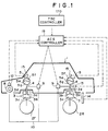
- the primary object of the present invention is to provide a suspension-traction total control system which controls the traction and the suspension properties in connection with each other, thereby effectively suppressing change of attitude of the vehicle body during the traction control.
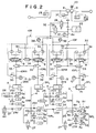
- An unload relief valve 28 is connected to the discharge passage 8a of the hydraulic pump 8 near the accumulator 22.
- the relief valve 28 is movable between an open position and a closed position. When the discharge pressure of the pump 8 as detected by the discharge pressure sensor 12 exceeds an upper limit, the relief valve 28 is opened to return hydraulic fluid from the pump 8 to a reservoir 29, thereby fixing the pressure of hydraulic fluid in the accumulator 22 to a preset value. To each of the fluid cylinders 3 is fed the hydraulic fluid accumulated in the accumulator 22.
- reference numeral 35 denotes a relief valve which opens and returns hydraulic fluid to the return passage 32 when the pressure in the liquid pressure chamber 3c of the fluid cylinder 3FL becomes abnormally high.
- Reference numeral 36 denotes a valve which is connected to the discharge passage 8a of the hydraulic pump 8 near the accumulator 22 and is interlocked with the ignition key. The valve 36 is opened after the ignition key is turned off and returns hydraulic fluid in the accumulator 22 to the reservoir 29.
- Reference numeral 37 denotes an in-pump relief valve which returns hydraulic fluid to the reservoir 29 when the discharge pressure of the hydraulic pump 8 becomes abnormally high.
- Reference numeral 38 denotes a return accumulator which is connected to the return passage 32 and accumulates the hydraulic pressure when hydraulic fluid is discharged from the fluid cylinder 3.
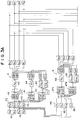
- the control variables calculated by the pitch control section 48 and the roll control section 49 are inverted in their signs for each wheel, that is, the signs of the control variables are inverted for each wheel so that they become opposite to the sign of the vehicle level displacement speed signal (YFR, YFL, YRR or YRL) calculated by the differentiator 46 for the wheel. Thereafter, the control variables for the pitch control and the roll control with the inverted signs are added together, and flow rate signals QFR2, QFL2, QRR2 and QRL2 for the flow control valves 9 for the respective wheels in the control system B are obtained.
- Mode 7 shows the control gains to be used instead of those for mode 4 when the vehicle is making a gentle turn with the lateral acceleration larger than 0.1 and not larger than 0.3 while reverse roll mode has been selected by a roll mode selection switch (not shown).
- a roll mode selection switch (not shown).
- QMAX stands for a maximum flow rate control variable to be fed to the proportional flow control valve 9 for each wheel
- PMAX stands for a maximum pressure in the liquid pressure chamber 3c of the fluid cylinder 3.
- the maximum pressure PMAX is set so that hydraulic fluid does not reverse from the liquid pressure chamber 3c to the accumulator 22.
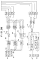
- brake fluid pressure the value of which depends upon the amount of depression of the brake pedal 125 is applied to the brakes 121RL and 121RR for the rear wheels from the booster 126 through the check valve 135.
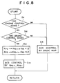
- FIG 5 shows the operation of the TRC controller 170 which is executed on the engine and the brake during the traction control.
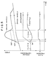
- a target value (a target slip value of the driving wheels) with respect to the engine is denoted by SET and a target value with respect to the brake is denoted by SBT. (SBT>SET)
- Figure 6 is block diagram for illustrating a circuit for determining the engine target value SET and the brake target value SBT. These values are determined according to the vehicle speed VS, the amount of depression of the accelerator pedal DP, the steering angle ⁇ , the position of the mode switch 171 and the maximum friction coefficient ⁇ max of road surface.
Landscapes
- Engineering & Computer Science (AREA)
- Mechanical Engineering (AREA)
- Transportation (AREA)
- Physics & Mathematics (AREA)
- Fluid Mechanics (AREA)
- Chemical & Material Sciences (AREA)
- Combustion & Propulsion (AREA)
- Automation & Control Theory (AREA)
- Vehicle Body Suspensions (AREA)
Claims (8)
- Kombiniertes Aufhängungs- und Traktions-Regelsystem für ein Fahrzeug (1), mit einer Traktions-Regeleinrichtung (TRC), die das Antriebsmoment an den Antriebsrädern des Fahrzeugs (1) bei deren Durchrutschen reduziert, und mit einer Aufhängung (ACS), die einen zwischen der Fahrzeugkarosserie und jedem der Räder (2) des Fahrzeugs (1) angeordneten Hydraulikzylinder (3) aufweist und in der die Aufhängungseigenschaften durch Steuerung der Hydraulikzylinder veränderbar sind und verändert werden können, wenn die Traktions-Regeleinrichtung (TRC) in Funktion ist, dadurch gekennzeichnet, daß die Aufhängung (ACS) eine Aufhängungs-Regeleinrichtung umfaßt, die auf der Grundlage der Ausgabesignale einer auf dem Fahrzeug (1) angeordneten Einrichtung (15) zur Ermittlung einer Beschleunigung der Fahrzeugkarosserie in weitgehend vertikaler Richtung Schwingungen der Fahrzeugkarosserie unterdrückt, und daß eine auf die genannten Ausgangssignale bezogene Regelverstärkung der Aufhängungs-Regeleinrichtung erhöht wird, wenn die Traktions-Regeleinrichtung (TRC) in Funktion ist.
- Kombiniertes Aufhängungs- und Traktions-Regelsystem nach Anspruch 1, in dem die Aufhängungs-Regeleinrichtung vertikale Schwingungen der Fahrzeugkarosserie auf der Grundlage von Abtastsignalen von Vertikal-Beschleunigungs-Sensoren (15) unterdrückt, welche Vertikalbeschleunigungen der Fahrzeugkarosserie gegenüber den Rädern erfassen.
- Kombiniertes Aufhängungs- und Traktions-Regelsystem nach Anspruch 1 oder 2, in dem die Traktions-Regeleinrichtung (TRC) zumindest den Motor (102) oder die Radbremsen (121) des Fahrzeugs steuert, um das Antriebsmoment zu reduzieren, und daß die Regelverstärkung der Aufhängungs-Regeleinrichtung erhöht wird, wenn die Traktions-Regeleinrichtung sowohl den Motor als auch die Radbremsen steuert.
- Kombiniertes Aufhängungs- und Traktions-Regelsystem nach Anspruch 3, in dem die Aufhängungs-Regeleinrichtung (ACS) weiterhin eine zweite Regeleinrichtung enthält, welche die Niveau-Verstellgeschwindigkeit des Fahrzeugs auf der Grundlage von Niveau-Verstellgeschwindigkeits-Signalen (XFR, XFL, XRR, XRL) hemmt, wobei die Niveau-Verstellgeschwindigkeits-Signale durch Differenzieren der Ausgangssignale von Fahrzeug-Niveau-Sensoren (14) an den jeweiligen Rädern erhalten werden, und daß die Regelverstärkung der Aufhängungs-Regeleinrichtung und der zweiten Regeleinrichtung erhöht wird, wenn die Traktions-Regeleinrichtung (TRC) sowohl den Motor als auch die Radbremsen steuert und der Wert der Brems-Regelgröße (BCV) nicht kleiner als ein vorbestimmter Wert (PBCV) ist.
- Kombiniertes Aufhängungs- und Traktions-Regelsystem nach Anspruch 3, in dem nur die Regelverstärkung der Aufhängungs-Regeleinrichtung erhöht wird, wenn die Traktions-Regeleinrichtung (TRC) sowohl den Motor als auch die Radbremsen steuert und der Wert der Brems-Regelgröße (BCV) kleiner als ein vorbestimmter Wert (PBCV) ist.
- Kombiniertes Aufhängungs- und Traktions-Regelsystem nach Anspruch 5, in dem die Regelverstärkung der Aufhängungs-Regeleinrichtung um einen kleineren Betrag erhöht wird, wenn die Traktions-Regeleinrichtung (TRC) sowohl den Motor als auch die Radbremsen steuert und der Wert der Brems-Regelgröße kleiner als der vorbestimmte Wert ist, als wenn die Traktions-Regeleinrichtung sowohl den Motor als auch die Radbremsen steuert und der Wert der Brems-Regelgröße nicht kleiner als der vorbestimmte Wert ist.
- Kombiniertes Aufhängungs- und Traktions-Regelsystem nach Anspruch 3, in dem die Regelverstärkung der Aufhängungs-Regeleinrichtung auf unterschiedliche Werte erhöht wird, wenn die Traktions-Regeleinrichtung (TRC) die Radbremsen an einem der linken und rechten Räder steuert, und wenn die Traktions-Regeleinrichtung die Radbremsen sowohl für die linken als auch die rechten Räder steuert.
- Kombiniertes Aufhängungs- und Traktions-Regelsystem nach Anspruch 1, in dem die Aufhängungseigenschaften durch Steuerung von Zufluß und Abfluß von Hydraulikmedium in die bzw. aus den Hydraulikzylindern (3) veränderbar sind.
Applications Claiming Priority (4)
| Application Number | Priority Date | Filing Date | Title |
|---|---|---|---|
| JP23818189 | 1989-09-13 | ||
| JP238181/89 | 1989-09-13 | ||
| JP74516/90 | 1990-03-23 | ||
| JP2074516A JP2945705B2 (ja) | 1989-09-13 | 1990-03-23 | サスペンションと駆動力の総合制御装置 |
Publications (3)
| Publication Number | Publication Date |
|---|---|
| EP0417792A2 EP0417792A2 (de) | 1991-03-20 |
| EP0417792A3 EP0417792A3 (en) | 1993-04-28 |
| EP0417792B1 true EP0417792B1 (de) | 1997-03-05 |
Family
ID=26415664
Family Applications (1)
| Application Number | Title | Priority Date | Filing Date |
|---|---|---|---|
| EP90117669A Expired - Lifetime EP0417792B1 (de) | 1989-09-13 | 1990-09-13 | Aufhängungs und Vortriebsverbundregelsystem |
Country Status (3)
| Country | Link |
|---|---|
| EP (1) | EP0417792B1 (de) |
| JP (1) | JP2945705B2 (de) |
| DE (1) | DE69030041T2 (de) |
Cited By (12)
| Publication number | Priority date | Publication date | Assignee | Title |
|---|---|---|---|---|
| US5694321A (en) | 1994-11-25 | 1997-12-02 | Itt Automotive Europe Gmbh | System for integrated driving stability control |
| US5701248A (en) | 1994-11-25 | 1997-12-23 | Itt Automotive Europe Gmbh | Process for controlling the driving stability with the king pin inclination difference as the controlled variable |
| US5710704A (en) | 1994-11-25 | 1998-01-20 | Itt Automotive Europe Gmbh | System for driving stability control during travel through a curve |
| US5711025A (en) | 1994-11-25 | 1998-01-20 | Itt Automotive Europe Gmbh | Driving stability control system with selective brake actuation |
| US5710705A (en) | 1994-11-25 | 1998-01-20 | Itt Automotive Europe Gmbh | Method for determining an additional yawing moment based on side slip angle velocity |
| US5711024A (en) | 1994-11-25 | 1998-01-20 | Itt Automotive Europe Gmbh | System for controlling yaw moment based on an estimated coefficient of friction |
| US5732378A (en) | 1994-11-25 | 1998-03-24 | Itt Automotive Europe Gmbh | Method for determining a wheel brake pressure |
| US5732377A (en) | 1994-11-25 | 1998-03-24 | Itt Automotive Europe Gmbh | Process for controlling driving stability with a yaw rate sensor equipped with two lateral acceleration meters |
| US5732379A (en) | 1994-11-25 | 1998-03-24 | Itt Automotive Europe Gmbh | Brake system for a motor vehicle with yaw moment control |
| US5742507A (en) | 1994-11-25 | 1998-04-21 | Itt Automotive Europe Gmbh | Driving stability control circuit with speed-dependent change of the vehicle model |
| US5774821A (en) | 1994-11-25 | 1998-06-30 | Itt Automotive Europe Gmbh | System for driving stability control |
| US10507825B2 (en) | 2016-11-08 | 2019-12-17 | Ford Global Technologies, Llc | Vehicle pitch control during a stop |
Families Citing this family (6)
| Publication number | Priority date | Publication date | Assignee | Title |
|---|---|---|---|---|
| GB9119103D0 (en) * | 1991-09-07 | 1991-10-23 | Motor Ind Res Ass | Suspension system |
| FR2714642B1 (fr) * | 1994-01-04 | 1996-03-08 | Peugeot | Dispositif d'antipatinage pour véhicule automobile. |
| JPH106951A (ja) * | 1996-04-26 | 1998-01-13 | Toyota Motor Corp | 車両の制御装置 |
| US6219602B1 (en) | 1999-04-01 | 2001-04-17 | Delphi Technologies, Inc. | Vehicle suspension control with stability in turn enhancement |
| US6181997B1 (en) | 1999-04-01 | 2001-01-30 | Delphi Technologies, Inc. | Vehicle suspension control with compensation for yaw correcting active brake control |
| SE520423C2 (sv) * | 2002-09-27 | 2003-07-08 | Scania Cv Abp | Förfarande och anordning för drivkraftsanpassning |
Family Cites Families (6)
| Publication number | Priority date | Publication date | Assignee | Title |
|---|---|---|---|---|
| JPS62110529A (ja) * | 1985-11-08 | 1987-05-21 | Nissan Motor Co Ltd | 車両用差動制限制御装置 |
| EP0231025B1 (de) * | 1986-01-30 | 1991-04-03 | Toyota Jidosha Kabushiki Kaisha | Steuerungsverfahren für das Fahrzeugverhalten |
| DE3783557T2 (de) * | 1986-10-24 | 1993-05-13 | Mazda Motor | Fahrzeugaufhaengungssystem mit veraenderlichen aufhaengungscharakteristiken. |
| DE3738284A1 (de) * | 1986-12-09 | 1988-06-30 | Bosch Gmbh Robert | Vorrichtung zur aktiven fahrwerkregelung bei kraftfahrzeugen |
| DE3731228A1 (de) * | 1987-09-17 | 1989-03-30 | Teves Gmbh Alfred | Regelbarer schwingungsdaempfer |
| JPH0195922A (ja) * | 1987-10-08 | 1989-04-14 | Mazda Motor Corp | 車両のサスペンション制御装置 |
-
1990
- 1990-03-23 JP JP2074516A patent/JP2945705B2/ja not_active Expired - Fee Related
- 1990-09-13 EP EP90117669A patent/EP0417792B1/de not_active Expired - Lifetime
- 1990-09-13 DE DE69030041T patent/DE69030041T2/de not_active Expired - Fee Related
Cited By (14)
| Publication number | Priority date | Publication date | Assignee | Title |
|---|---|---|---|---|
| US5694321A (en) | 1994-11-25 | 1997-12-02 | Itt Automotive Europe Gmbh | System for integrated driving stability control |
| US5701248A (en) | 1994-11-25 | 1997-12-23 | Itt Automotive Europe Gmbh | Process for controlling the driving stability with the king pin inclination difference as the controlled variable |
| US5710704A (en) | 1994-11-25 | 1998-01-20 | Itt Automotive Europe Gmbh | System for driving stability control during travel through a curve |
| US5711025A (en) | 1994-11-25 | 1998-01-20 | Itt Automotive Europe Gmbh | Driving stability control system with selective brake actuation |
| US5710705A (en) | 1994-11-25 | 1998-01-20 | Itt Automotive Europe Gmbh | Method for determining an additional yawing moment based on side slip angle velocity |
| US5711024A (en) | 1994-11-25 | 1998-01-20 | Itt Automotive Europe Gmbh | System for controlling yaw moment based on an estimated coefficient of friction |
| US5711023A (en) | 1994-11-25 | 1998-01-20 | Itt Automotive Europe Gmbh | System for determining side slip angle |
| US5732378A (en) | 1994-11-25 | 1998-03-24 | Itt Automotive Europe Gmbh | Method for determining a wheel brake pressure |
| US5732377A (en) | 1994-11-25 | 1998-03-24 | Itt Automotive Europe Gmbh | Process for controlling driving stability with a yaw rate sensor equipped with two lateral acceleration meters |
| US5732379A (en) | 1994-11-25 | 1998-03-24 | Itt Automotive Europe Gmbh | Brake system for a motor vehicle with yaw moment control |
| US5742507A (en) | 1994-11-25 | 1998-04-21 | Itt Automotive Europe Gmbh | Driving stability control circuit with speed-dependent change of the vehicle model |
| US5774821A (en) | 1994-11-25 | 1998-06-30 | Itt Automotive Europe Gmbh | System for driving stability control |
| US5862503A (en) | 1994-11-25 | 1999-01-19 | Itt Automotive Europe Gmbh | System for driving stability control |
| US10507825B2 (en) | 2016-11-08 | 2019-12-17 | Ford Global Technologies, Llc | Vehicle pitch control during a stop |
Also Published As
| Publication number | Publication date |
|---|---|
| DE69030041T2 (de) | 1997-06-12 |
| EP0417792A3 (en) | 1993-04-28 |
| JPH03176221A (ja) | 1991-07-31 |
| EP0417792A2 (de) | 1991-03-20 |
| DE69030041D1 (de) | 1997-04-10 |
| JP2945705B2 (ja) | 1999-09-06 |
Similar Documents
| Publication | Publication Date | Title |
|---|---|---|
| US5183127A (en) | Suspension-traction total control system | |
| EP0417792B1 (de) | Aufhängungs und Vortriebsverbundregelsystem | |
| US5037119A (en) | Suspension-steering control apparatus | |
| EP0488052B1 (de) | Steuersystem für den Fahrzustand eines Kraftfahrzeuges | |
| DE69008026T2 (de) | Federungssystem für Fahrzeuge. | |
| EP0725737A1 (de) | Fahrzeugaufhängungssystem | |
| US5100167A (en) | Suspension system for automotive vehicle | |
| EP0311114B1 (de) | Aktiv geregeltes Kraftfahrzeugaufhängungssystem mit fahrzeuggeschwindigkeitsabhängigen Dämpfungscharakteristiken | |
| US5176399A (en) | Suspension apparatus of automotive vehicle | |
| US5251134A (en) | Suspension system for automotive vehicle | |
| US5015006A (en) | Suspension apparatus of a vehicle | |
| US5218545A (en) | Suspension apparatus of automotive vehicle with control system having a variable time constant | |
| US4978135A (en) | Vehicle suspension system | |
| US5060969A (en) | Suspension apparatus of a vehicle | |
| JP2954606B2 (ja) | 車両の総合制御装置 | |
| JPH06122309A (ja) | 車両のサスペンション装置 | |
| JP3059199B2 (ja) | 電子制御流体圧サスペンション | |
| JPH09142118A (ja) | サスペンション制御装置 | |
| JP3020656B2 (ja) | 車両のサスペンシヨン装置 | |
| JP2839911B2 (ja) | 車両のサスペンション装置 | |
| JP3049148B2 (ja) | 車両のサスペンション装置 | |
| AU676785B2 (en) | Vehicle suspension system | |
| JP3096048B2 (ja) | 車両のサスペンション装置 | |
| JP3082859B2 (ja) | 車両のサスペンション装置 | |
| JPH04278818A (ja) | 車両のサスペンション装置 |
Legal Events
| Date | Code | Title | Description |
|---|---|---|---|
| PUAI | Public reference made under article 153(3) epc to a published international application that has entered the european phase |
Free format text: ORIGINAL CODE: 0009012 |
|
| AK | Designated contracting states |
Kind code of ref document: A2 Designated state(s): DE FR GB |
|
| PUAL | Search report despatched |
Free format text: ORIGINAL CODE: 0009013 |
|
| AK | Designated contracting states |
Kind code of ref document: A3 Designated state(s): DE FR GB |
|
| 17P | Request for examination filed |
Effective date: 19930817 |
|
| 17Q | First examination report despatched |
Effective date: 19930916 |
|
| GRAG | Despatch of communication of intention to grant |
Free format text: ORIGINAL CODE: EPIDOS AGRA |
|
| GRAH | Despatch of communication of intention to grant a patent |
Free format text: ORIGINAL CODE: EPIDOS IGRA |
|
| GRAH | Despatch of communication of intention to grant a patent |
Free format text: ORIGINAL CODE: EPIDOS IGRA |
|
| GRAA | (expected) grant |
Free format text: ORIGINAL CODE: 0009210 |
|
| AK | Designated contracting states |
Kind code of ref document: B1 Designated state(s): DE FR GB |
|
| REF | Corresponds to: |
Ref document number: 69030041 Country of ref document: DE Date of ref document: 19970410 |
|
| ET | Fr: translation filed | ||
| PGFP | Annual fee paid to national office [announced via postgrant information from national office to epo] |
Ref country code: FR Payment date: 19970716 Year of fee payment: 8 |
|
| PGFP | Annual fee paid to national office [announced via postgrant information from national office to epo] |
Ref country code: GB Payment date: 19970904 Year of fee payment: 8 |
|
| PLBE | No opposition filed within time limit |
Free format text: ORIGINAL CODE: 0009261 |
|
| STAA | Information on the status of an ep patent application or granted ep patent |
Free format text: STATUS: NO OPPOSITION FILED WITHIN TIME LIMIT |
|
| 26N | No opposition filed | ||
| PG25 | Lapsed in a contracting state [announced via postgrant information from national office to epo] |
Ref country code: GB Free format text: LAPSE BECAUSE OF NON-PAYMENT OF DUE FEES Effective date: 19980913 |
|
| GBPC | Gb: european patent ceased through non-payment of renewal fee |
Effective date: 19980913 |
|
| PG25 | Lapsed in a contracting state [announced via postgrant information from national office to epo] |
Ref country code: FR Free format text: LAPSE BECAUSE OF NON-PAYMENT OF DUE FEES Effective date: 19990531 |
|
| REG | Reference to a national code |
Ref country code: FR Ref legal event code: ST |
|
| PGFP | Annual fee paid to national office [announced via postgrant information from national office to epo] |
Ref country code: DE Payment date: 20011001 Year of fee payment: 12 |
|
| PG25 | Lapsed in a contracting state [announced via postgrant information from national office to epo] |
Ref country code: DE Free format text: LAPSE BECAUSE OF NON-PAYMENT OF DUE FEES Effective date: 20030401 |