EP0417660B1 - Vorrichtung zur Aufhellung von Cockpitinstrumenten - Google Patents
Vorrichtung zur Aufhellung von Cockpitinstrumenten Download PDFInfo
- Publication number
- EP0417660B1 EP0417660B1 EP90117268A EP90117268A EP0417660B1 EP 0417660 B1 EP0417660 B1 EP 0417660B1 EP 90117268 A EP90117268 A EP 90117268A EP 90117268 A EP90117268 A EP 90117268A EP 0417660 B1 EP0417660 B1 EP 0417660B1
- Authority
- EP
- European Patent Office
- Prior art keywords
- reflecting
- deviating
- set forth
- daylight
- cockpit
- Prior art date
- Legal status (The legal status is an assumption and is not a legal conclusion. Google has not performed a legal analysis and makes no representation as to the accuracy of the status listed.)
- Expired - Lifetime
Links
- 238000005286 illumination Methods 0.000 title 1
- XAGFODPZIPBFFR-UHFFFAOYSA-N aluminium Chemical compound [Al] XAGFODPZIPBFFR-UHFFFAOYSA-N 0.000 claims description 2
- 229910052782 aluminium Inorganic materials 0.000 claims description 2
- 238000005282 brightening Methods 0.000 description 13
- 230000004313 glare Effects 0.000 description 2
- 229920003229 poly(methyl methacrylate) Polymers 0.000 description 2
- 239000004926 polymethyl methacrylate Substances 0.000 description 2
- 230000006978 adaptation Effects 0.000 description 1
- 239000003086 colorant Substances 0.000 description 1
- 230000001419 dependent effect Effects 0.000 description 1
- 238000009434 installation Methods 0.000 description 1
- 239000004973 liquid crystal related substance Substances 0.000 description 1
- 238000004519 manufacturing process Methods 0.000 description 1
- 238000012986 modification Methods 0.000 description 1
- 230000004048 modification Effects 0.000 description 1
Images


Classifications
-
- G—PHYSICS
- G01—MEASURING; TESTING
- G01D—MEASURING NOT SPECIALLY ADAPTED FOR A SPECIFIC VARIABLE; ARRANGEMENTS FOR MEASURING TWO OR MORE VARIABLES NOT COVERED IN A SINGLE OTHER SUBCLASS; TARIFF METERING APPARATUS; MEASURING OR TESTING NOT OTHERWISE PROVIDED FOR
- G01D11/00—Component parts of measuring arrangements not specially adapted for a specific variable
- G01D11/28—Structurally-combined illuminating devices
Definitions
- the invention relates to a device for brightening cockpit instruments by daylight, comprising a light passage opening for daylight falling through front windows in a cover screen and a deflecting mirror assigned to the light passage opening for daylight to brighten the cockpit instruments.
- Aircraft cockpits are exposed to constantly changing directions of light and light intensities due to changing flight conditions. Various precautions have been taken to avoid glare and reflections. For this reason, for example, the cockpit is kept in dark colors. The incidence of light in the cockpit is reduced. This optimizes the view from the aircraft. However, there are difficulties in reading the cockpit instruments during the day. The pilot's eye is adapted to the strong brightness of the light entering through the front window of the cockpit. The difference in brightness between the field of view observed through the front window and the dark cockpit makes it difficult to read the instruments.
- the integrated night lighting of the cockpit instruments is designed for dark eyes. During daytime operation, night lighting can hardly make any contribution to improving readability. An increase in the illuminance of such an "active" instrument lighting would require additional energy, additional heat production and more and stronger wiring and thus also more weight.
- DE-A-2 944 537 relates to such an instrument lighting device of the aforementioned type, for example in an aircraft.
- an inner one Light source has a facility through which daylight is directed onto the instruments.
- a light guide part is provided, one edge surface of which extends through an upper padding or a glare shield against the front window and through which incident daylight is introduced into the light guide part.
- the light-guiding part forms a plate that runs behind the dials on the dashboard; its rear side facing away from the dials is a reflective surface and its front side facing the dials is a surface emitting the incident deflected daylight.
- the invention has for its object to provide a device of the type mentioned, the installation of which does not require any intervention in the instrument panel.
- this object is achieved in that the light passage opening and the deflecting mirror are arranged in the viewing direction of the viewer in front of the scales of the cockpit instruments and that the daylight can be deflected by the deflecting mirror as incident light onto the cockpit instruments.
- the cockpit instruments are therefore not brightened in transmitted light but in reflected light using daylight. This brightening of the cockpit instruments is automatically adjusted to the outside brightness and thus to the adaptation state of the eye. There is no need to install or modify the instrument panel containing the cockpit instruments.
- Embodiments of the invention are the subject of the dependent claims.
- 10 denotes an instrument panel in the cockpit of an aircraft.
- the instrument panel 10 contains a cockpit instrument 12 in the form of a liquid crystal display.
- a cover screen 14 is arranged above the instrument panel 10.
- the cockpit front window (not shown) is located above the cover screen 14.
- the cockpit instrument 12 is illuminated by a brightening device.
- the brightening device is generally designated 16.
- This lightening device 16 allows daylight from the front window of the cockpit to be directed onto the cockpit instrument 12 in a targeted manner.
- the brightening device 16 contains a deflecting mirror 18.
- the deflecting mirror 18 is inserted into the cover screen 14.
- the cover screen 14 has a light passage opening 20.
- the light passage opening 20 is covered by a translucent cover 22.
- the cover 22 can be a cover, for example made of acrylic glass or a grate.
- the deflecting mirror 18 consists of rolled, over-polished aluminum sheet.
- the deflection mirror can be a plane mirror, as shown in FIG. 1.
- the deflection mirror 18 can also be convex or concave.
- the deflection mirror 18 can have a different curvature in the horizontal section than in the vertical section. As a result, the incident light beams can be distributed over the instrument panel 10 in the desired manner. This is shown schematically in FIGS. 3 and 4.
- FIG. 2 shows an arrangement which largely corresponds to the arrangement according to FIG. 1. Corresponding parts are provided with the same reference numerals as in FIG. 1. Instead of a cover made of acrylic glass, the light passage opening 20 in the embodiment according to FIG. 2 is covered by a blind 28.
- the blind 28 only allows beams 24 and 26 to pass through from a certain angular range. This prevents the incidence of light from undesired directions of incidence 30, for example from above.
- the brightening device contains, instead of the deflecting mirror 18, a diffusely reflecting element 32 which is exposed to daylight from the front windows of the cockpit and which diffuses against the cockpit instruments reflected.
- 34 and 36 are incident rays of daylight.
- the diffusely reflecting rays are identified by 38. Otherwise, the arrangement according to FIG. 5 is the same as the arrangement according to FIG. 1.
- Brightening devices have been described in connection with the instrument panel of an aircraft. Brightening devices of this type can be used in the same or a corresponding manner for the same purpose in connection with instrument panels of other vehicles or systems.
Landscapes
- Physics & Mathematics (AREA)
- General Physics & Mathematics (AREA)
- Instrument Panels (AREA)
- Optical Elements Other Than Lenses (AREA)
- Details Of Measuring Devices (AREA)
- Details Of Measuring And Other Instruments (AREA)
- Lenses (AREA)
- Arrangements Of Lighting Devices For Vehicle Interiors, Mounting And Supporting Thereof, Circuits Therefore (AREA)
Description
- Die Erfindung betrifft eine Vorrichtung zur Aufhellung von Cockpit-Instrumenten durch Tageslicht, enthaltend eine Lichtdurchtrittsöffnung für durch Frontfenster fallendes Tageslicht in einem Abdeckschirm und einen der Lichtdurchtrittsöffnung zugeordneten Umlenkspiegel für das Tageslicht zur Aufhellung der Cockpit-Instrumente.
- Cockpits von Flugzeugen sind durch wechselnde Flugbedingungen ständig wechselnden Lichteinfallsrichtungen und Lichtintensitäten ausgesetzt. Es sind verschiedene Vorkehrungen getroffen worden, um Blendungen und Reflexionen zu vermeiden. Aus diesem Grunde ist beispielsweise das Cockpit in dunklen Farben gehalten. Der Lichteinfall in das Cockpit ist reduziert. Dadurch ist der Ausblick aus dem Flugzeug optimiert. Es ergeben sich aber Schwierigkeiten, die Cockpit-Instrumente bei Tag abzulesen. Das Auge des Piloten ist an die starke Helligkeit des durch das Frontfenster des Cockpits einfallenden Lichtes adaptiert. Durch die Helligkeitsdifferenz zwischen dem durch das Frontfenster beobachteten Gesichtsfeld und dem dunklen Cockpit wird die Ablesung der Instrumente schwierig.
- Die integrierte Nachtbeleuchtung der Cockpit-Instrumente ist für dunkel angepasste Augen ausgelegt. Die Nachtbeleuchtung kann im Tagbetrieb kaum Beiträge zur Verbesserung der Ablesbarkeit liefern. Eine Erhöhung der Beleuchtungsstärke einer solchen "aktiven" Instrumentenbeleuchtung würde zusätzlichen Energiebedarf, zusätzliche Wärmeproduktion sowie mehr und stärkere Verkabelungen und somit auch mehr Gewicht bedingen.
- Die DE-A-2 944 537 betrifft eine solche Instrumenten-Beleuchtungseinrichtung der vorgenannten Art zum Beispiel in einem Flugzeug. Darin ist zusätzlich zu einer inneren Lichtquelle eine Einrichtung vorhanden, durch die Tageslicht auf die Instrumente gerichtet wird. Für diesen Zweck ist ein Lichtleitteil vorgesehen, dessen eine Kantenfläche sich durch eine obere Polsterung oder einen Blendschutz gegen das Frontfenster erstreckt und durch die einfallendes Tageslicht in den Lichtleitteil eingeleitet wird. Der Lichtleitteil bildet eine Platte, die hinter den Skalenblättern des Armaturenbrettes verläuft; ihre den Skalenblättern abgewandte Rückseite ist eine reflektierende Fläche und ihre den Skalenblättern zugewandte Vorderseite ist eine das einfallende umgelenkte Tageslicht emittierende Fläche. Bei dieser Anordnung wird somit das einfallende Tageslicht hinter die dem Betrachter zugewandte Seite des Instrumentes geleitet, und die Aufhellung wird durch das Tageslicht bewirkt, das als Durchlicht durch das Skalenblatt hindurchfällt.
- Der Erfindung liegt die Aufgabe zugrunde, eine Vorrichtung der eingangs genannten Art zu schaffen, deren Einbau keinen Eingriff in die Instrumententafel erfordert.
- Erfindungsgemäss wird diese Aufgabe dadurch gelöst, dass die Lichtdurchtrittsöffnung und der Umlenkspiegel in Blickrichtung des Betrachters vor den Skalen der Cockpit-Instrumente angeordnet sind und dass das Tageslicht durch den Umlenkspiegel als Auflicht auf die Cockpit-Instrumente umlenkbar ist.
- Nach der Erfindung erfolgt somit die Aufhellung der Cockpit-Instrumente nicht im Durchlicht sondern im Auflicht unter Ausnutzung des Tageslichtes. Diese Aufhellung der Cockpit-Instrumente ist automatisch an die Aussenhelligkeit angepasst und damit an den Adaptionszustand des Auges. Es sind dazu keine Ein- oder Umbauten an der die Cockpit-Instrumente enthaltenden Instrumententafel notwendig.
- Ausgestaltungen der Erfindung sind Gegenstand der Unteransprüche.
- Ein Ausführungsbeispiel der Erfindung ist nachstehend unter Bezugnahme auf die zugehörigen Zeichnungen näher erläutert:
- Fig. 1
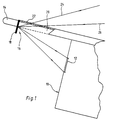
- zeigt schematisch einen Vertikalschnitt durch einen Teil des Cockpits mit einem Cockpit-Instrument und einem Abdeckschirm, der ein Ausführungsbeispiel der erfindungsgemässen Aufhellungsvorrichtung enthält;
- Fig. 2
- ist eine abgewandelte Ausführung in einer Darstellung ähnlich Fig. 1, bei welcher nur eine bestimmte Richtung des durch das Frontfenster einfallenden Lichtes für die Aufhellung der Cockpit-Instrumente benutzt wird.
- Fig. 3, 4 und 5
- zeigen weitere Abwandlungen des Ausführungsbeispieles.
- In Fig. 1 ist mit 10 ein Instrumentenfeld im Cockpit eines Flugzeuges bezeichnet. Das Instrumentenfeld 10 enthält ein Cockpit-Instrument 12 in Form einer Flüssigkristallanzeige. Über dem Instrumentenfeld 10 ist ein Abdeckschirm 14 angeordnet. Über dem Abdeckschirm 14 befindet sich das (nicht dargestellte) Frontfenster des Cockpits.
- Das Cockpit-Instrument 12 wird durch eine Aufhellvorrichtung beleuchtet. Die Aufhellvorrichtung ist generell mit 16 bezeichnet. Durch diese Aufhellvorrichtung 16 kann Tageslicht aus dem Frontfenster des Cockpits gezielt auf das Cockpit-Instrument 12 gerichtet werden. Die Aufhellvorrichtung 16 enthält einen Umlenkspiegel 18. Der Umlenkspiegel 18 ist in den Abdeckschirm 14 eingesetzt. Zu diesem Zweck weist der Abdeckschirm 14 eine Lichtdurchtrittsöffnung 20 auf. Die Lichtdurchtrittsöffnung 20 ist durch eine lichtdurchlässige Abdeckung 22 abgedeckt. Die Abdeckung 22 kann z.B. ein Deckel aus Acrylglas oder ein Rost sein. Der Umlenkspiegel 18 besteht aus gewalztem, überpoliertem Aluminiumblech.
- Wie aus Fig. 1 ersichtlich ist, fällt Licht, welches durch das Frontfenster des Cockpits eintritt, durch die Lichtdurchtrittsöffnung 20 hindurch auf den Umlenkspiegel 18. Das Licht zwischen den Strahlen 24 und 26 wird auf das Cockpit-Instrument 12 geleitet. Dadurch erfolgt eine Aufhellung des Cockpit-Instruments 12. Diese Aufhellung tritt auch ein, wenn das Cockpit-Instrument 12 dicht unter dem Abdeckschirm 14 sitzt, wie dies hier der Fall ist. Die Aufhellung ist um so stärker, je intensiver das durch das Frontfenster eintretende Licht ist. Sie passt sich also automatisch an die Helligkeit des vom Piloten beobachteten Gesichtsfeldes an.
- Der Umlenkspiegel kann ein Planspiegel sein, wie dies in Fig. 1 dargestellt ist. Der Umlenkspiegel 18 kann aber auch konvex oder konkav sein. Der Umlenkspiegel 18 kann im Horizontalschnitt eine andere Krümmung aufweisen als im Vertikalschnitt. Dadurch können die einfallenden Lichtstrahlen in der gewünschten Weise auf das Instrumentenfeld 10 verteilt werden. Das ist in Fig. 3 und 4 schematisch dargestellt.
- Fig. 2 zeigt eine Anordnung, die weitgehend mit der Anordnung nach Fig. 1 übereinstimmt. Entsprechende Teile sind mit den gleichen Bezugszeichen versehen wie in Fig. 1. Statt durch einen Deckel aus Acrylglas ist die Lichtdurchtrittsöffnung 20 bei der Ausführung nach Fig. 2 durch eine Jalousie 28 abgedeckt. Die Jalousie 28 lässt nur Strahlen 24 und 26 aus einem bestimmten Winkelbereich hindurchtreten. Dadurch wird Lichteinfall aus unerwünschten Einfallsrichtungen 30, zum Beispiel von oben, verhindert.
- Bei der Ausführung nach Fig. 5 enthält die Aufhellvorrichtung statt des Umlenkspiegels 18 ein diffus reflektierendes Glied 32, welches vom Tageslicht aus den Frontfenstern des Cockpits beaufschlagt ist und dieses diffus gegen die Cockpit-Instrumente reflektiert. In Fig. 5 sind mit 34 und 36 einfallende Strahlen des Tageslichts bezeichnet. Die diffus reflektierenden Strahlen sind mit 38 gekennzeichnet. Im übrigen ist die Anordnung nach Fig. 5 die gleiche wie die Anordnung nach Fig. 1.
- Die vorstehenden Aufhellungsvorrichtungen sind im Zusammenhang mit der Instrumententafel eines Flugzeuges beschrieben worden. Aufhellungsvorrichtungen dieser Art können in gleicher oder entsprechender Weise zu dem gleichen Zweck in Verbindung mit Instrumententafeln anderer Fahrzeuge oder Anlagen eingesetzt werden.
Claims (10)
- Vorrichtung zur Aufhellung von Cockpit-Instrumenten durch Tageslicht, enthaltend eine Lichtdurchtrittsöffnung (20) für durch Frontfenster fallendes Tageslicht in einem Abdeckschirm (14) und eine der Lichtdurchtrittsöffnung (20) zugeordnetes, reflektierendes Umlenkglied (18, 32) für das Tageslicht zur Aufhellung der Cockpit-Instrumente,
dadurch gekennzeichnet, dass
die Lichtdurchtrittsöffnung (20) und das reflektierende Umlenkglied (18, 32) in Blickrichtung des Betrachters vor den Skalen der Cockpit-Instrumente (12) angeordnet sind und dass das Tageslicht durch das reflektierende Umlenkglied (18, 32) als Auflicht auf die Cockpit-Instrument umlenkbar ist. - Vorrichtung nach Anspruch 1, dadurch gekennzeichnet, dass das reflektierende Umlenkglied (18) am inneren Rand der Öffnung (20) angebracht ist.
- Vorrichtung nach Anspruch 2, dadurch gekennzeichnet, dass die Lichtdurchtrittsöffnung (20) durch eine lichtdurchlässige Abdeckung (22) abgedeckt ist.
- Vorrichtung nach einem der Ansprüche 1 bis 3, dadurch gekennzeichnet, dass das reflektierende Umlenkglied (18) ein Planspiegel ist.
- Vorrichtung nach einem der Ansprüche 1 bis 3, dadurch gekennzeichnet, dass das reflektierende Umlenkglied ein konvexer Umlenkspiegel ist.
- Vorrichtung nach einem der Ansprüche 1 bis 3, dadurch gekennzeichnet, dass das reflektierende Umlenkglied ein konkaver Umlenkspiegel ist.
- Vorrichtung nach Anspruch 5 oder 6, dadurch gekennzeichnet, dass der Umlenkspiegel (18) im Horizontalschnitt eine andere Krümmung aufweist als im Vertikalschnitt.
- Vorrichtung nach einem der Ansprüche 1 bis 7, gekennzeichnet durch eine Jalousie (28) im Strahlengang der Aufhelleinrichtung (16), wobei die Jalousie (28) den zugelassenen Lichtdurchtrittswinkel beeinflusst.
- Vorrichtung nach einem der Ansprüche 1 bis 8, dadurch gekennzeichnet, dass der Umlenkspiegel (18) aus gewalztem, überpolierten Aluminiumblech besteht.
- Vorrichtung nach Anspruch 1, dadurch gekennzeichnet, dass das reflektierende Umlenkglied ein diffus reflektierendes Glied (32) ist, das vom Tageslicht aus den Frontfenstern des Cockpits beaufschlagt ist und dieses diffus gegen die Cockpit-Instrumente reflektiert.
Applications Claiming Priority (2)
| Application Number | Priority Date | Filing Date | Title |
|---|---|---|---|
| DE3930359 | 1989-09-12 | ||
| DE3930359A DE3930359A1 (de) | 1989-09-12 | 1989-09-12 | Vorrichtung zur aufhellung von cockpitinstrumenten |
Publications (2)
| Publication Number | Publication Date |
|---|---|
| EP0417660A1 EP0417660A1 (de) | 1991-03-20 |
| EP0417660B1 true EP0417660B1 (de) | 1994-04-13 |
Family
ID=6389211
Family Applications (1)
| Application Number | Title | Priority Date | Filing Date |
|---|---|---|---|
| EP90117268A Expired - Lifetime EP0417660B1 (de) | 1989-09-12 | 1990-09-07 | Vorrichtung zur Aufhellung von Cockpitinstrumenten |
Country Status (5)
| Country | Link |
|---|---|
| US (1) | US5140472A (de) |
| EP (1) | EP0417660B1 (de) |
| JP (1) | JPH03118246A (de) |
| DE (2) | DE3930359A1 (de) |
| IL (1) | IL95636A0 (de) |
Families Citing this family (6)
| Publication number | Priority date | Publication date | Assignee | Title |
|---|---|---|---|---|
| DE3512910A1 (de) * | 1985-04-11 | 1986-10-16 | Behringwerke Ag, 3550 Marburg | Verfahren zur reinigung von plasminogenaktivatoren |
| US6179452B1 (en) | 1998-07-27 | 2001-01-30 | Stephen C. Dunning | Aircraft lighting system |
| US6422723B1 (en) | 2000-06-09 | 2002-07-23 | Robert Charles Walters | Portable cockpit illumination device |
| DE10208109B4 (de) * | 2002-02-26 | 2006-04-13 | Kastriot Merlaku | Innenbeleuchtungssytem für einen Hubschrauber |
| DE10208111B4 (de) * | 2002-02-26 | 2006-04-13 | Kastriot Merlaku | Innenbeleuchtungssystem für ein Flugzeug |
| DE102012007473A1 (de) * | 2012-04-13 | 2013-10-17 | Airbus Operations Gmbh | Tageslichteinleitung in Luftfahrzeugen |
Family Cites Families (13)
| Publication number | Priority date | Publication date | Assignee | Title |
|---|---|---|---|---|
| DE739720C (de) * | 1941-03-04 | 1943-10-02 | Dornier Werke Gmbh | Flaechenleuchte fuer Flugzeug-Instrumentenbeleuchtung |
| US2375134A (en) * | 1943-12-11 | 1945-05-01 | Ptacek Anna | Concentration mirror for airplanes |
| US2695354A (en) * | 1950-12-16 | 1954-11-23 | Edwin A Neugass | Instrument panel lighting |
| DE1955159U (de) * | 1966-12-14 | 1967-02-09 | Metrawatt Ag Fabrik Elek Scher | Vorrichtung zur indirekten beleuchtung von messgeraeteskalen. |
| US3559929A (en) * | 1969-06-10 | 1971-02-02 | David B Lindsay Jr | Ordnance actuation controls within the range of vision of a pilot looking forward from a cockpit |
| US4072406A (en) * | 1976-06-17 | 1978-02-07 | Amesbury Maurice G | Camera periscope with louvers for controlling light scattering |
| US4310871A (en) * | 1978-11-06 | 1982-01-12 | Nissan Motor Co., Ltd. | Illuminating device for instrument |
| JPS5622468A (en) * | 1979-08-01 | 1981-03-03 | Nissan Motor | Liquid crystal display unit |
| DE3207871A1 (de) * | 1982-03-05 | 1983-09-15 | Robert Bosch Gmbh, 7000 Stuttgart | Anzeigevorrichtung, insbesondere fuer kraftfahrzeuge |
| DE3245299A1 (de) * | 1982-12-08 | 1984-06-14 | Bosch Gmbh Robert | Anzeigevorrichtung in kraftfahrzeugen |
| US4729634A (en) * | 1985-02-04 | 1988-03-08 | United Technologies Corporation | Reflective head-up display |
| US4905935A (en) * | 1988-03-21 | 1990-03-06 | Loral Corporation | Aircraft windshield transparency |
| US5056854A (en) * | 1991-05-02 | 1991-10-15 | Rosen John B | Sun visor system |
-
1989
- 1989-09-12 DE DE3930359A patent/DE3930359A1/de not_active Withdrawn
-
1990
- 1990-09-07 DE DE59005341T patent/DE59005341D1/de not_active Expired - Fee Related
- 1990-09-07 EP EP90117268A patent/EP0417660B1/de not_active Expired - Lifetime
- 1990-09-10 US US07/580,149 patent/US5140472A/en not_active Expired - Fee Related
- 1990-09-10 IL IL95636A patent/IL95636A0/xx unknown
- 1990-09-11 JP JP2242291A patent/JPH03118246A/ja active Pending
Also Published As
| Publication number | Publication date |
|---|---|
| IL95636A0 (en) | 1991-06-30 |
| US5140472A (en) | 1992-08-18 |
| JPH03118246A (ja) | 1991-05-20 |
| DE59005341D1 (de) | 1994-05-19 |
| DE3930359A1 (de) | 1991-03-28 |
| EP0417660A1 (de) | 1991-03-20 |
Similar Documents
| Publication | Publication Date | Title |
|---|---|---|
| EP4115218B1 (de) | Anordnung zur reflexionsunterdrückung bei einem frontscheibenanzeigesystem sowie frontscheibenanzeigesystem | |
| DE19732156B4 (de) | Zusammengesetzte Anzeigetafel | |
| DE4242797C2 (de) | Head-Up-Display-System | |
| DE4323082C2 (de) | Anzeigeeinheit für Kraftfahrzeuge | |
| DE2910489A1 (de) | Anzeigenaufbau fuer kraftfahrzeuge | |
| DE10144075B4 (de) | Head-Up-Display | |
| DE69022932T2 (de) | "Head-up Display" für Kraftfahrzeuge mit antireflektierendem Jalousie-Filter. | |
| DE2944537A1 (de) | Instrumenten-beleuchtungseinrichtung | |
| DE112019002950T5 (de) | Anzeigevorrichtung und Head-up-Display-Vorrichtung | |
| DE10026892A1 (de) | Kombiinstrument für ein Kraftfahrzeug | |
| DE112018000055B4 (de) | Rückspiegel mit der Funktion zum Anzeigen einer Armaturentafel sowie dessen Steuersystem | |
| DE4335854B4 (de) | Anzeigevorrichtung | |
| DE3688656T2 (de) | Flüssigkristall-Anzeigevorrichtung. | |
| DE112019003192T5 (de) | Head-up-Display-Vorrichtung | |
| DE69212869T2 (de) | Anzeigevorrichtung für Fahrzeuge | |
| EP0417660A1 (de) | Vorrichtung zur Aufhellung von Cockpitinstrumenten | |
| DE102009058141A1 (de) | Anzeigevorrichtung für ein Fahrzeug | |
| DE10033776A1 (de) | Scheinwerfer für ein Kraftfahrzeug | |
| EP0603465B1 (de) | Verfahren und Anordnung zur optischen Darstellung von Informationen | |
| DE2064025C3 (de) | Informationsgeber für Kraftfahrzeuge | |
| DE3032344A1 (de) | Fluessigkeitskristallanzeigen | |
| DE102018220243A1 (de) | Messvorrichtung und mit der Messvorrichtung versehene Messeinheit | |
| DE3314323A1 (de) | Vorrichtung zur ausleuchtung passiver anzeigen | |
| DE10107256A1 (de) | Anzeigenvorrichtung | |
| EP0107757A1 (de) | Vorrichtung zur Ausleuchtung passiver Anzeigen |
Legal Events
| Date | Code | Title | Description |
|---|---|---|---|
| PUAI | Public reference made under article 153(3) epc to a published international application that has entered the european phase |
Free format text: ORIGINAL CODE: 0009012 |
|
| AK | Designated contracting states |
Kind code of ref document: A1 Designated state(s): DE FR GB IT |
|
| 17P | Request for examination filed |
Effective date: 19910806 |
|
| 17Q | First examination report despatched |
Effective date: 19930413 |
|
| GRAA | (expected) grant |
Free format text: ORIGINAL CODE: 0009210 |
|
| AK | Designated contracting states |
Kind code of ref document: B1 Designated state(s): DE FR GB IT |
|
| GBT | Gb: translation of ep patent filed (gb section 77(6)(a)/1977) |
Effective date: 19940420 |
|
| REF | Corresponds to: |
Ref document number: 59005341 Country of ref document: DE Date of ref document: 19940519 |
|
| ITF | It: translation for a ep patent filed | ||
| ET | Fr: translation filed | ||
| PLBE | No opposition filed within time limit |
Free format text: ORIGINAL CODE: 0009261 |
|
| STAA | Information on the status of an ep patent application or granted ep patent |
Free format text: STATUS: NO OPPOSITION FILED WITHIN TIME LIMIT |
|
| 26N | No opposition filed | ||
| PGFP | Annual fee paid to national office [announced via postgrant information from national office to epo] |
Ref country code: GB Payment date: 19950824 Year of fee payment: 6 |
|
| PGFP | Annual fee paid to national office [announced via postgrant information from national office to epo] |
Ref country code: FR Payment date: 19950828 Year of fee payment: 6 |
|
| PGFP | Annual fee paid to national office [announced via postgrant information from national office to epo] |
Ref country code: DE Payment date: 19951125 Year of fee payment: 6 |
|
| PG25 | Lapsed in a contracting state [announced via postgrant information from national office to epo] |
Ref country code: GB Effective date: 19960907 |
|
| PG25 | Lapsed in a contracting state [announced via postgrant information from national office to epo] |
Ref country code: FR Effective date: 19960930 |
|
| GBPC | Gb: european patent ceased through non-payment of renewal fee |
Effective date: 19960907 |
|
| PG25 | Lapsed in a contracting state [announced via postgrant information from national office to epo] |
Ref country code: DE Effective date: 19970603 |
|
| REG | Reference to a national code |
Ref country code: FR Ref legal event code: ST |
|
| REG | Reference to a national code |
Ref country code: FR Ref legal event code: ST |
|
| PG25 | Lapsed in a contracting state [announced via postgrant information from national office to epo] |
Ref country code: IT Free format text: LAPSE BECAUSE OF NON-PAYMENT OF DUE FEES Effective date: 20050907 |