EP0416640B1 - Méthode de fabrication d'un coupleur optique fusionné et coupleur ainsi fabriqué - Google Patents
Méthode de fabrication d'un coupleur optique fusionné et coupleur ainsi fabriqué Download PDFInfo
- Publication number
- EP0416640B1 EP0416640B1 EP90117241A EP90117241A EP0416640B1 EP 0416640 B1 EP0416640 B1 EP 0416640B1 EP 90117241 A EP90117241 A EP 90117241A EP 90117241 A EP90117241 A EP 90117241A EP 0416640 B1 EP0416640 B1 EP 0416640B1
- Authority
- EP
- European Patent Office
- Prior art keywords
- coupler
- fibres
- polarization
- fibers
- output
- Prior art date
- Legal status (The legal status is an assumption and is not a legal conclusion. Google has not performed a legal analysis and makes no representation as to the accuracy of the status listed.)
- Expired - Lifetime
Links
- 238000004519 manufacturing process Methods 0.000 title claims abstract description 11
- 230000003287 optical effect Effects 0.000 title claims description 10
- 239000000835 fiber Substances 0.000 claims abstract description 58
- 230000004927 fusion Effects 0.000 claims abstract description 30
- 230000010287 polarization Effects 0.000 claims abstract description 26
- 230000008878 coupling Effects 0.000 claims abstract description 8
- 238000010168 coupling process Methods 0.000 claims abstract description 8
- 238000005859 coupling reaction Methods 0.000 claims abstract description 8
- 238000005253 cladding Methods 0.000 claims abstract description 7
- 238000000034 method Methods 0.000 claims abstract description 6
- 230000010363 phase shift Effects 0.000 claims description 2
- 238000006880 cross-coupling reaction Methods 0.000 claims 1
- 230000035945 sensitivity Effects 0.000 claims 1
- 238000002835 absorbance Methods 0.000 description 1
- 230000005540 biological transmission Effects 0.000 description 1
- 238000005516 engineering process Methods 0.000 description 1
- 238000007499 fusion processing Methods 0.000 description 1
- 238000003780 insertion Methods 0.000 description 1
- 230000037431 insertion Effects 0.000 description 1
- 238000002844 melting Methods 0.000 description 1
- 230000008018 melting Effects 0.000 description 1
- 238000010309 melting process Methods 0.000 description 1
- 230000001681 protective effect Effects 0.000 description 1
- 238000000926 separation method Methods 0.000 description 1
Images
Classifications
-
- G—PHYSICS
- G02—OPTICS
- G02B—OPTICAL ELEMENTS, SYSTEMS OR APPARATUS
- G02B6/00—Light guides; Structural details of arrangements comprising light guides and other optical elements, e.g. couplings
- G02B6/24—Coupling light guides
- G02B6/26—Optical coupling means
- G02B6/28—Optical coupling means having data bus means, i.e. plural waveguides interconnected and providing an inherently bidirectional system by mixing and splitting signals
- G02B6/293—Optical coupling means having data bus means, i.e. plural waveguides interconnected and providing an inherently bidirectional system by mixing and splitting signals with wavelength selective means
- G02B6/29331—Optical coupling means having data bus means, i.e. plural waveguides interconnected and providing an inherently bidirectional system by mixing and splitting signals with wavelength selective means operating by evanescent wave coupling
- G02B6/29332—Wavelength selective couplers, i.e. based on evanescent coupling between light guides, e.g. fused fibre couplers with transverse coupling between fibres having different propagation constant wavelength dependency
-
- G—PHYSICS
- G02—OPTICS
- G02B—OPTICAL ELEMENTS, SYSTEMS OR APPARATUS
- G02B6/00—Light guides; Structural details of arrangements comprising light guides and other optical elements, e.g. couplings
- G02B6/24—Coupling light guides
- G02B6/26—Optical coupling means
- G02B6/28—Optical coupling means having data bus means, i.e. plural waveguides interconnected and providing an inherently bidirectional system by mixing and splitting signals
- G02B6/2804—Optical coupling means having data bus means, i.e. plural waveguides interconnected and providing an inherently bidirectional system by mixing and splitting signals forming multipart couplers without wavelength selective elements, e.g. "T" couplers, star couplers
- G02B6/2821—Optical coupling means having data bus means, i.e. plural waveguides interconnected and providing an inherently bidirectional system by mixing and splitting signals forming multipart couplers without wavelength selective elements, e.g. "T" couplers, star couplers using lateral coupling between contiguous fibres to split or combine optical signals
- G02B6/2835—Optical coupling means having data bus means, i.e. plural waveguides interconnected and providing an inherently bidirectional system by mixing and splitting signals forming multipart couplers without wavelength selective elements, e.g. "T" couplers, star couplers using lateral coupling between contiguous fibres to split or combine optical signals formed or shaped by thermal treatment, e.g. couplers
-
- G—PHYSICS
- G02—OPTICS
- G02B—OPTICAL ELEMENTS, SYSTEMS OR APPARATUS
- G02B6/00—Light guides; Structural details of arrangements comprising light guides and other optical elements, e.g. couplings
- G02B6/24—Coupling light guides
- G02B6/26—Optical coupling means
- G02B6/28—Optical coupling means having data bus means, i.e. plural waveguides interconnected and providing an inherently bidirectional system by mixing and splitting signals
- G02B6/2804—Optical coupling means having data bus means, i.e. plural waveguides interconnected and providing an inherently bidirectional system by mixing and splitting signals forming multipart couplers without wavelength selective elements, e.g. "T" couplers, star couplers
- G02B6/2821—Optical coupling means having data bus means, i.e. plural waveguides interconnected and providing an inherently bidirectional system by mixing and splitting signals forming multipart couplers without wavelength selective elements, e.g. "T" couplers, star couplers using lateral coupling between contiguous fibres to split or combine optical signals
- G02B6/2843—Optical coupling means having data bus means, i.e. plural waveguides interconnected and providing an inherently bidirectional system by mixing and splitting signals forming multipart couplers without wavelength selective elements, e.g. "T" couplers, star couplers using lateral coupling between contiguous fibres to split or combine optical signals the couplers having polarisation maintaining or holding properties
Definitions
- the invention relates to a method for producing an optical fusion coupler according to the preamble of claim 1.
- Such couplers are used in systems of optical communications technology.
- the invention has for its object to provide a method for producing a polarization-selective optical fusion coupler with a short drawing length and a fusion coupler produced thereafter, which consists of non-birefringent single-mode fibers with matched cladding and which is easier and cheaper to manufacture than the comparable known fusion couplers.
- This object is achieved by the features specified in claim 1.
- Advantageous method steps and designs of the fusion coupler can be found in the subclaims.
- the solution found has the advantage, among other things, that the fusion area of the coupler has only a short pulling length. It is therefore handy and relatively insensitive to damage even before it is embedded in a protective housing. It is also easier to manufacture, which saves time and money. Further advantages are mentioned in the description.
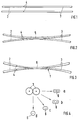
- the input fibers of the fusion coupler 1 to be produced are referred to as couplers 2 in the following. They are polarization-maintaining single-mode fibers, the ends of which end with a normal, non-birefringent one Single mode matched cladding type fibers are connected by splicing.
- the splices are preferably connections which are produced in a known manner by integrally fusing the fiber ends.
- the non-birefringent single-mode fibers form the output fibers 3, which at the same time represent the connecting fibers.
- the pair of fibers is fixed in a pulling device (not shown) in such a way that the main optical axes of the polarization-maintaining single-mode fibers (input fibers 2) are parallel and perpendicular to the coupler axis, and the non-birefringent single-mode fibers (output fibers 3) are in an area that is one has a relatively short distance to the splice connections 4 lying parallel to one another, the fibers being unchanged in cross section. Subsequently, light is coupled into one of the input fibers 2 and detected at the end of both output fibers 3. The non-birefringent single-mode fibers are then fused together at the contact point 5 (FIG.
- a drawing length of 10 mm to 15 mm is sufficient.
- the drawing length is preferably approximately 11 mm to 13 mm. The drawing length is thus advantageously only slightly longer than that of wavelength-selective fusion couplers.
- the coupler 1 (FIG. 4b), which is preferably manufactured with a medium degree of fusion, shows the wavelength dependence of a wavelength-selective fusion coupler for linearly polarized light (perpendicular or parallel to the coupler plane). There is a phase shift of 180 ° in the wavelength dependence of the two polarization directions.
- the crosstalk attenuation between the two polarization directions (perpendicular and parallel to the coupler plane) is approximately 19 dB to 25 dB in a relatively large usable wavelength range, while the degree of polarization in the outgoing fibers (output fibers 3) is also very high and Absorbance values of approx. 25 dB to 30 dB reached.
- This coupler 1 with non-birefringent single-mode fibers thus combines the properties of two couplers, as have been proposed in DE-OS 37 16 247.0 by K. Pedestrian for a transmission system with wavelength and polarization multiplex.
- the wavelength spacing of adjacent channels in the coupler 1 is approximately 50 nm. At the 3dB point, where there is the same amount of light in both channels, the coupler 1 shows no polarization selectivity. 25 nm further, at larger or smaller wavelength, there is maximum polarization selectivity. This is used to optimize the polarization-selective coupler 1. If the coupler 1 is required, for example, at a wavelength of 1530 nm, then linearly polarized light of the wavelength 1505 nm is coupled into an input fiber 2. The melting process is initiated by the application of heat. During the fusion process, the light couples over to the other fiber during the drawing, then back again, etc., the light coupling less and less completely with increasing drawing length.
- the pulling process is stopped when the mutual coupling stagnates and thus the same amount of light is present in both channels.
- the light and heat sources are switched off, the coupler 1 with the connecting fibers is removed from the pulling device and then fastened mechanically protected in a housing. This is preferably done in such a way that the fibers leading from the fusion region 6 to a connecting fiber, including the splice connections 4, lie without curvature in the coupler housing and are fixed therein. In this way, the connection fibers (input / output fibers 2, 3) are kept strain relieved.
- the polarization-selective coupler 1 thus produced has very good properties. In addition to a relatively short overall length, it is characterized by very low insertion losses, which are less than 0.5 dB. It can be used to couple two lasers of the same wavelength to one fiber ("laser redundancy", e.g. for underwater amplifiers). For this purpose, the polarized light of one laser is coupled in parallel, that of the other perpendicular to the coupler plane. In this case, the laser light is combined in the coupler onto a standard single-mode fiber. To ensure this, the polarization-maintaining fibers (input fibers 2) are used between the laser and the coupler 1. Otherwise there would be fluctuations in intensity which would lead to noise (“polarization noise"). The division of the incoming laser light into mutually perpendicular components allows the coupler to be used for polarization diversity reception.
- laser redundancy e.g. for underwater amplifiers
- both the wavelength and the polarization are divided in the coupler 1, as a result of which a high far-end crosstalk attenuation is ensured.
Landscapes
- Physics & Mathematics (AREA)
- General Physics & Mathematics (AREA)
- Optics & Photonics (AREA)
- Optical Couplings Of Light Guides (AREA)
- Optical Fibers, Optical Fiber Cores, And Optical Fiber Bundles (AREA)
- Mechanical Coupling Of Light Guides (AREA)
- Glass Compositions (AREA)
- Joining Of Glass To Other Materials (AREA)
- Optical Communication System (AREA)
Claims (9)
- Procédé de fabrication d'un coupleur de fusion (1) optique sélectif en matière de polarisation ayant plusieurs fibres d'entrée (2) et des fibres de sortie (3) qui, dans la zone de couplage, se compose de deux fibres monomodes parallèles non biréfringentes à gaines appariées qui sous l'effet de la chaleur fusionnent ensemble et dont la zone de fusion résultante (6) est étirée dans le sens axial jusqu'à coupure de la source de chaleur, caractérisé en ce que les fibres d'entrée (2) composées de fibres entretenant la polarisation sont d'abord épissées avec des fibres de sortie (3) composées de fibres monomodes non biréfringentes à gaines appariées, en ce qu'une lumière polarisée de manière linéaire d'une longueur d'onde choisie est ensuite introduite dans une des fibres d'entrée (2) et détectée aux extrémités des deux fibres de sortie (3), en ce que les fibres de sortie (3) fusionnent ensemble et en ce que le coupleur (1) est étiré jusqu'à ce que le surcouplage réciproque entre les deux fibres de sortie (3) stagne et que la source de chaleur soit coupée.
- Coupleur de fusion optique sélectif en matière de polarisation fabriqué selon le procédé de la revendication 1 ayant plusieurs fibres d'entrée entretenant la polarisation et des fibres de sortie sous forme de fibres monomodes non biréfringentes à gaines appariées épissées ensemble, dans lequel les fibres de sortie sont parallèles dans la zone de couplage, fusionnent ensemble et sont étirées et dans lequel la longueur de la zone de fusion est de 10 à 15 mm.
- Coupleur selon la revendication 2 dans lequel les fibres monomodes entretenant la polarisation (fibres d'entrée 2) comportent des axes optiques principaux parallèles et perpendiculaires à la zone de couplage.
- Coupleur selon la revendication 2 dans lequel les fibres menant de la zone de fusion (6) à une des fibres d'entrée ou de sortie (2, 3) sont placées bien à plat dans le boîtier du coupleur et sont fixées en même temps que les points d'épissure (4) dans le boîtier du coupleur.
- Coupleur selon la revendication 2 dans lequel le coupleur est sélectif en matière de polarisation pour une lumière d'une certaine gamme d'ondes.
- Coupleur selon la revendication 2 dans lequel le coupleur est sélectif en matière de longueur d'onde pour une lumière présentant un sens de polarisation parallèle ou perpendiculaire à la zone de couplage.
- Coupleur selon la revendication 2 dans lequel le coupleur présente pratiquement la même dépendance vis-à-vis de la longueur d'onde pour une lumière présentant un sens de polarisation parallèle et pour une lumière présentant un sens de polarisation perpendiculaire à la zone de couplage et dans lequel un décalage de phase de 180 °C existe entre les deux sens de polarisation.
- Coupleur selon la revendication 2 dans lequel le coupleur sélectionne la polarisation et la longueur d'onde pour deux longueurs d'onde différentes.
- Coupleur selon la revendication 2 à 8 dans lequel les fibres monomodes (fibres de sortie 3) présentent dans la zone de fusion (6) un degré moyen de fusion des surfaces latérales n'ayant qu'un faible rétrécissement.
Applications Claiming Priority (2)
| Application Number | Priority Date | Filing Date | Title |
|---|---|---|---|
| DE3930035A DE3930035A1 (de) | 1989-09-08 | 1989-09-08 | Verfahren zur herstellung eines optischen verschmelzkopplers und danach hergestellter koppler |
| DE3930035 | 1989-09-08 |
Publications (3)
| Publication Number | Publication Date |
|---|---|
| EP0416640A2 EP0416640A2 (fr) | 1991-03-13 |
| EP0416640A3 EP0416640A3 (en) | 1992-01-22 |
| EP0416640B1 true EP0416640B1 (fr) | 1996-11-27 |
Family
ID=6389005
Family Applications (1)
| Application Number | Title | Priority Date | Filing Date |
|---|---|---|---|
| EP90117241A Expired - Lifetime EP0416640B1 (fr) | 1989-09-08 | 1990-09-07 | Méthode de fabrication d'un coupleur optique fusionné et coupleur ainsi fabriqué |
Country Status (8)
| Country | Link |
|---|---|
| US (1) | US5064267A (fr) |
| EP (1) | EP0416640B1 (fr) |
| JP (1) | JPH03100604A (fr) |
| AT (1) | ATE145636T1 (fr) |
| AU (1) | AU632359B2 (fr) |
| DE (2) | DE3930035A1 (fr) |
| DK (1) | DK0416640T3 (fr) |
| ES (1) | ES2097123T3 (fr) |
Families Citing this family (11)
| Publication number | Priority date | Publication date | Assignee | Title |
|---|---|---|---|---|
| DE3930029A1 (de) * | 1989-09-08 | 1991-03-21 | Standard Elektrik Lorenz Ag | Verfahren zum herstellen eines optischen verschmelzkopplers |
| DE4109982A1 (de) * | 1991-03-27 | 1992-10-01 | Standard Elektrik Lorenz Ag | Verfahren zur herstellung eines optischen verschmelzkopplers |
| US6701046B1 (en) * | 1999-09-30 | 2004-03-02 | Corning O.T.I. Spa | Method for producing an optical coupler for extracting a signal from a polarization maintaining optical fiber, and corresponding coupler |
| CA2289962C (fr) * | 1999-11-17 | 2006-01-17 | Itf Optical Technologies Inc.-Technologies Optiques Itf Inc. | Fabrication de photocoupleurs de fibres monomodes de multiplexage et de demultiplexage |
| KR100358418B1 (ko) * | 2000-02-28 | 2002-10-25 | 한국과학기술원 | 용융형 모드분할 방향성 결합기의 제조방법 |
| US6813414B1 (en) * | 2000-07-17 | 2004-11-02 | Finisar Corporation | Fiber optical pigtail geometry for improved extinction ratio of polarization maintaining fibers |
| CA2354903C (fr) | 2001-08-08 | 2008-10-14 | Itf Technologies Optiques Inc./Itf Optical Technologies Inc. | Coupleur optique de fibres etirees a combinaison de polarisations et methode de fabrication connexe |
| CA2465602C (fr) * | 2003-09-29 | 2009-09-22 | Accelink Technologies Co., Ltd. | Diviseur de puissance optique independant de la polarisation permettant d'effectuer une division variable |
| JP2008076685A (ja) * | 2006-09-20 | 2008-04-03 | National Institute Of Advanced Industrial & Technology | 端面近接多芯光ファイバーおよびその製造方法 |
| DE102012110203A1 (de) * | 2012-10-25 | 2014-04-30 | Deutsches Zentrum für Luft- und Raumfahrt e.V. | Verfahren und Vorrichtung zur Herstellung eines optischen Kabels mit mehreren Glasfasersträngen |
| CN104749988B (zh) | 2013-12-26 | 2017-12-05 | 同方威视技术股份有限公司 | 用于物体检测的光电开关 |
Citations (1)
| Publication number | Priority date | Publication date | Assignee | Title |
|---|---|---|---|---|
| EP0246737A2 (fr) * | 1986-05-23 | 1987-11-25 | Nortel Networks Corporation | Coupleur directif |
Family Cites Families (10)
| Publication number | Priority date | Publication date | Assignee | Title |
|---|---|---|---|---|
| US4360248A (en) * | 1979-04-18 | 1982-11-23 | International Telephone And Telegraph Corporation | Multiport optical communication system and optical star structure therefor |
| US4737005A (en) * | 1982-12-17 | 1988-04-12 | The United States Of America As Represented By The Secretary Of The Navy | Method for eliminating birefringence in a fiber optic coupler and a coupler polarization corrector |
| USRE33296E (en) * | 1983-05-26 | 1990-08-14 | Gould Inc. | Method of making a polarization-insensitive, evanescent-wave, fused coupler with minimal environmental sensitivity |
| US4743497A (en) * | 1985-08-08 | 1988-05-10 | Phillips Petroleum Company | Laminated puncture sealing composite and preparation thereof |
| US4834481A (en) * | 1985-11-12 | 1989-05-30 | Gould Inc. | In-line single-mode fiber optic multiplexer/demultiplexer |
| JPS63175812A (ja) * | 1987-01-17 | 1988-07-20 | Nippon Telegr & Teleph Corp <Ntt> | 光フアイバカツプラ作製方法 |
| DE3716247C2 (de) * | 1987-05-15 | 1994-04-28 | Sel Alcatel Ag | Optisches Nachrichtenübertragungssystem mit Wellenlängen- und Polarisations-Multiplex |
| US4906068A (en) * | 1988-09-01 | 1990-03-06 | Minnesota Mining And Manufacturing Company | Polarization-maintaining optical fibers for coupler fabrication |
| US4932740A (en) * | 1989-06-05 | 1990-06-12 | Corning Incorporated | Method of making polarization retaining optical fiber coupler |
| DE3930029A1 (de) * | 1989-09-08 | 1991-03-21 | Standard Elektrik Lorenz Ag | Verfahren zum herstellen eines optischen verschmelzkopplers |
-
1989
- 1989-09-08 DE DE3930035A patent/DE3930035A1/de not_active Withdrawn
-
1990
- 1990-08-31 AU AU62031/90A patent/AU632359B2/en not_active Ceased
- 1990-09-07 ES ES90117241T patent/ES2097123T3/es not_active Expired - Lifetime
- 1990-09-07 DK DK90117241.1T patent/DK0416640T3/da active
- 1990-09-07 AT AT90117241T patent/ATE145636T1/de not_active IP Right Cessation
- 1990-09-07 EP EP90117241A patent/EP0416640B1/fr not_active Expired - Lifetime
- 1990-09-07 DE DE59010579T patent/DE59010579D1/de not_active Expired - Fee Related
- 1990-09-10 US US07/580,920 patent/US5064267A/en not_active Expired - Fee Related
- 1990-09-10 JP JP2239780A patent/JPH03100604A/ja active Pending
Patent Citations (1)
| Publication number | Priority date | Publication date | Assignee | Title |
|---|---|---|---|---|
| EP0246737A2 (fr) * | 1986-05-23 | 1987-11-25 | Nortel Networks Corporation | Coupleur directif |
Also Published As
| Publication number | Publication date |
|---|---|
| ATE145636T1 (de) | 1996-12-15 |
| ES2097123T3 (es) | 1997-04-01 |
| AU632359B2 (en) | 1992-12-24 |
| EP0416640A2 (fr) | 1991-03-13 |
| EP0416640A3 (en) | 1992-01-22 |
| US5064267A (en) | 1991-11-12 |
| DE3930035A1 (de) | 1991-03-21 |
| JPH03100604A (ja) | 1991-04-25 |
| DK0416640T3 (da) | 1997-04-28 |
| AU6203190A (en) | 1991-03-14 |
| DE59010579D1 (de) | 1997-01-09 |
Similar Documents
| Publication | Publication Date | Title |
|---|---|---|
| DE69800007T2 (de) | Vorrichtung mit kaskadiertem Ramanfaserlaser | |
| DE69132794T2 (de) | Optische Kommunikationssysteme mit koaxialem Koppler | |
| DE69120402T2 (de) | Faseroptischer Verstärker mit Filter | |
| DE69838840T2 (de) | Aktiver optischer wellenleiter mit asymmetrischer polarisation, dessen herstellungsverfahren und seine verwendung. | |
| DE69131615T2 (de) | Miniatur faseroptische biege-vorrichtung und methode | |
| DE3782537T2 (de) | Richtkoppler. | |
| DE69404110T2 (de) | Verstärker mit Faserfilterpumpsystem | |
| EP0390002B1 (fr) | Système optique de transmission de communications Diplex ou Duplex | |
| CH644975A5 (de) | Lichtleitfaser-richtkoppler und dessen verwendung in einer sende-/empfangseinrichtung. | |
| EP0012189B1 (fr) | Elément coupleur pour dériver une fraction de lumière d'un guide d'ondes optique comprenant une fibre entourée d'une gaine | |
| DE2729008A1 (de) | Optische wellenleiter-anordnung | |
| DE2745940A1 (de) | Optisches schaltkreiselement | |
| DE3221836C2 (de) | Einzelmodenfaser | |
| EP0622649A1 (fr) | Coupleur optique avec point de prise | |
| DE2851667C2 (fr) | ||
| EP0265918B1 (fr) | Système optique de transmission de données large bande, en particulier pour la zone de raccordement d'abonnés | |
| EP0416640B1 (fr) | Méthode de fabrication d'un coupleur optique fusionné et coupleur ainsi fabriqué | |
| DE69731252T2 (de) | Übertragungssystem mit preisgünstigem optischem Filter | |
| DE19700682C2 (de) | Optische Add/Drop-Schaltung mit Lichtleitergitter | |
| DE69122766T2 (de) | Optisches netzwerk | |
| DE69808111T2 (de) | Optischer koppler und/oder multiplexer | |
| EP0287925B1 (fr) | Coupleur étoile à fibre optique | |
| DE69014493T2 (de) | Faseroptischer Kuppler. | |
| EP0048855A2 (fr) | Elément de réglage de la transmission de lumière entre des guides d'ondes optiques | |
| EP0505828A1 (fr) | Méthode de fabrication d'un coupleur optique fusionné |
Legal Events
| Date | Code | Title | Description |
|---|---|---|---|
| PUAI | Public reference made under article 153(3) epc to a published international application that has entered the european phase |
Free format text: ORIGINAL CODE: 0009012 |
|
| AK | Designated contracting states |
Kind code of ref document: A2 Designated state(s): AT BE CH DE DK ES FR GB IT LI NL SE |
|
| PUAL | Search report despatched |
Free format text: ORIGINAL CODE: 0009013 |
|
| AK | Designated contracting states |
Kind code of ref document: A3 Designated state(s): AT BE CH DE DK ES FR GB IT LI NL SE |
|
| 17P | Request for examination filed |
Effective date: 19920613 |
|
| RAP3 | Party data changed (applicant data changed or rights of an application transferred) |
Owner name: ALCATEL N.V. Owner name: ALCATEL SEL AKTIENGESELLSCHAFT |
|
| 17Q | First examination report despatched |
Effective date: 19940816 |
|
| GRAG | Despatch of communication of intention to grant |
Free format text: ORIGINAL CODE: EPIDOS AGRA |
|
| GRAH | Despatch of communication of intention to grant a patent |
Free format text: ORIGINAL CODE: EPIDOS IGRA |
|
| GRAH | Despatch of communication of intention to grant a patent |
Free format text: ORIGINAL CODE: EPIDOS IGRA |
|
| GRAA | (expected) grant |
Free format text: ORIGINAL CODE: 0009210 |
|
| AK | Designated contracting states |
Kind code of ref document: B1 Designated state(s): AT BE CH DE DK ES FR GB IT LI NL SE |
|
| REF | Corresponds to: |
Ref document number: 145636 Country of ref document: AT Date of ref document: 19961215 Kind code of ref document: T |
|
| REG | Reference to a national code |
Ref country code: CH Ref legal event code: NV Representative=s name: JUERG ULRICH C/O ALCATEL STR AG |
|
| GBT | Gb: translation of ep patent filed (gb section 77(6)(a)/1977) |
Effective date: 19961127 |
|
| ITF | It: translation for a ep patent filed | ||
| REF | Corresponds to: |
Ref document number: 59010579 Country of ref document: DE Date of ref document: 19970109 |
|
| ET | Fr: translation filed | ||
| REG | Reference to a national code |
Ref country code: ES Ref legal event code: FG2A Ref document number: 2097123 Country of ref document: ES Kind code of ref document: T3 |
|
| REG | Reference to a national code |
Ref country code: DK Ref legal event code: T3 |
|
| PGFP | Annual fee paid to national office [announced via postgrant information from national office to epo] |
Ref country code: GB Payment date: 19970811 Year of fee payment: 8 |
|
| PGFP | Annual fee paid to national office [announced via postgrant information from national office to epo] |
Ref country code: SE Payment date: 19970820 Year of fee payment: 8 Ref country code: FR Payment date: 19970820 Year of fee payment: 8 Ref country code: DK Payment date: 19970820 Year of fee payment: 8 |
|
| PGFP | Annual fee paid to national office [announced via postgrant information from national office to epo] |
Ref country code: NL Payment date: 19970821 Year of fee payment: 8 Ref country code: DE Payment date: 19970821 Year of fee payment: 8 |
|
| PGFP | Annual fee paid to national office [announced via postgrant information from national office to epo] |
Ref country code: AT Payment date: 19970822 Year of fee payment: 8 |
|
| PGFP | Annual fee paid to national office [announced via postgrant information from national office to epo] |
Ref country code: CH Payment date: 19970828 Year of fee payment: 8 Ref country code: BE Payment date: 19970828 Year of fee payment: 8 |
|
| PGFP | Annual fee paid to national office [announced via postgrant information from national office to epo] |
Ref country code: ES Payment date: 19970926 Year of fee payment: 8 |
|
| PLBE | No opposition filed within time limit |
Free format text: ORIGINAL CODE: 0009261 |
|
| STAA | Information on the status of an ep patent application or granted ep patent |
Free format text: STATUS: NO OPPOSITION FILED WITHIN TIME LIMIT |
|
| 26N | No opposition filed | ||
| PG25 | Lapsed in a contracting state [announced via postgrant information from national office to epo] |
Ref country code: GB Free format text: LAPSE BECAUSE OF NON-PAYMENT OF DUE FEES Effective date: 19980907 Ref country code: DK Free format text: LAPSE BECAUSE OF NON-PAYMENT OF DUE FEES Effective date: 19980907 Ref country code: AT Free format text: LAPSE BECAUSE OF NON-PAYMENT OF DUE FEES Effective date: 19980907 |
|
| PG25 | Lapsed in a contracting state [announced via postgrant information from national office to epo] |
Ref country code: SE Free format text: LAPSE BECAUSE OF NON-PAYMENT OF DUE FEES Effective date: 19980908 Ref country code: ES Free format text: LAPSE BECAUSE OF EXPIRATION OF PROTECTION Effective date: 19980908 |
|
| PG25 | Lapsed in a contracting state [announced via postgrant information from national office to epo] |
Ref country code: LI Free format text: LAPSE BECAUSE OF NON-PAYMENT OF DUE FEES Effective date: 19980930 Ref country code: CH Free format text: LAPSE BECAUSE OF NON-PAYMENT OF DUE FEES Effective date: 19980930 Ref country code: BE Free format text: LAPSE BECAUSE OF NON-PAYMENT OF DUE FEES Effective date: 19980930 |
|
| BERE | Be: lapsed |
Owner name: ALCATEL N.V. Effective date: 19980930 |
|
| PG25 | Lapsed in a contracting state [announced via postgrant information from national office to epo] |
Ref country code: NL Free format text: LAPSE BECAUSE OF NON-PAYMENT OF DUE FEES Effective date: 19990401 |
|
| GBPC | Gb: european patent ceased through non-payment of renewal fee |
Effective date: 19980907 |
|
| REG | Reference to a national code |
Ref country code: CH Ref legal event code: PL |
|
| EUG | Se: european patent has lapsed |
Ref document number: 90117241.1 |
|
| PG25 | Lapsed in a contracting state [announced via postgrant information from national office to epo] |
Ref country code: FR Free format text: LAPSE BECAUSE OF NON-PAYMENT OF DUE FEES Effective date: 19990531 |
|
| NLV4 | Nl: lapsed or anulled due to non-payment of the annual fee |
Effective date: 19990401 |
|
| PG25 | Lapsed in a contracting state [announced via postgrant information from national office to epo] |
Ref country code: DE Free format text: LAPSE BECAUSE OF NON-PAYMENT OF DUE FEES Effective date: 19990701 |
|
| REG | Reference to a national code |
Ref country code: FR Ref legal event code: ST |
|
| REG | Reference to a national code |
Ref country code: DK Ref legal event code: EBP |
|
| REG | Reference to a national code |
Ref country code: ES Ref legal event code: FD2A Effective date: 20010201 |
|
| PG25 | Lapsed in a contracting state [announced via postgrant information from national office to epo] |
Ref country code: IT Free format text: LAPSE BECAUSE OF NON-PAYMENT OF DUE FEES;WARNING: LAPSES OF ITALIAN PATENTS WITH EFFECTIVE DATE BEFORE 2007 MAY HAVE OCCURRED AT ANY TIME BEFORE 2007. THE CORRECT EFFECTIVE DATE MAY BE DIFFERENT FROM THE ONE RECORDED. Effective date: 20050907 |