EP0416640B1 - Method of fabrication of a fused optical coupler and coupler manufactured accordingly - Google Patents
Method of fabrication of a fused optical coupler and coupler manufactured accordingly Download PDFInfo
- Publication number
- EP0416640B1 EP0416640B1 EP90117241A EP90117241A EP0416640B1 EP 0416640 B1 EP0416640 B1 EP 0416640B1 EP 90117241 A EP90117241 A EP 90117241A EP 90117241 A EP90117241 A EP 90117241A EP 0416640 B1 EP0416640 B1 EP 0416640B1
- Authority
- EP
- European Patent Office
- Prior art keywords
- coupler
- fibres
- polarization
- fibers
- output
- Prior art date
- Legal status (The legal status is an assumption and is not a legal conclusion. Google has not performed a legal analysis and makes no representation as to the accuracy of the status listed.)
- Expired - Lifetime
Links
- 238000004519 manufacturing process Methods 0.000 title claims abstract description 11
- 230000003287 optical effect Effects 0.000 title claims description 10
- 239000000835 fiber Substances 0.000 claims abstract description 58
- 230000004927 fusion Effects 0.000 claims abstract description 30
- 230000010287 polarization Effects 0.000 claims abstract description 26
- 230000008878 coupling Effects 0.000 claims abstract description 8
- 238000010168 coupling process Methods 0.000 claims abstract description 8
- 238000005859 coupling reaction Methods 0.000 claims abstract description 8
- 238000005253 cladding Methods 0.000 claims abstract description 7
- 238000000034 method Methods 0.000 claims abstract description 6
- 230000010363 phase shift Effects 0.000 claims description 2
- 238000006880 cross-coupling reaction Methods 0.000 claims 1
- 230000035945 sensitivity Effects 0.000 claims 1
- 238000002835 absorbance Methods 0.000 description 1
- 230000005540 biological transmission Effects 0.000 description 1
- 238000005516 engineering process Methods 0.000 description 1
- 238000007499 fusion processing Methods 0.000 description 1
- 238000003780 insertion Methods 0.000 description 1
- 230000037431 insertion Effects 0.000 description 1
- 238000002844 melting Methods 0.000 description 1
- 230000008018 melting Effects 0.000 description 1
- 238000010309 melting process Methods 0.000 description 1
- 230000001681 protective effect Effects 0.000 description 1
- 238000000926 separation method Methods 0.000 description 1
Images
Classifications
-
- G—PHYSICS
- G02—OPTICS
- G02B—OPTICAL ELEMENTS, SYSTEMS OR APPARATUS
- G02B6/00—Light guides; Structural details of arrangements comprising light guides and other optical elements, e.g. couplings
- G02B6/24—Coupling light guides
- G02B6/26—Optical coupling means
- G02B6/28—Optical coupling means having data bus means, i.e. plural waveguides interconnected and providing an inherently bidirectional system by mixing and splitting signals
- G02B6/293—Optical coupling means having data bus means, i.e. plural waveguides interconnected and providing an inherently bidirectional system by mixing and splitting signals with wavelength selective means
- G02B6/29331—Optical coupling means having data bus means, i.e. plural waveguides interconnected and providing an inherently bidirectional system by mixing and splitting signals with wavelength selective means operating by evanescent wave coupling
- G02B6/29332—Wavelength selective couplers, i.e. based on evanescent coupling between light guides, e.g. fused fibre couplers with transverse coupling between fibres having different propagation constant wavelength dependency
-
- G—PHYSICS
- G02—OPTICS
- G02B—OPTICAL ELEMENTS, SYSTEMS OR APPARATUS
- G02B6/00—Light guides; Structural details of arrangements comprising light guides and other optical elements, e.g. couplings
- G02B6/24—Coupling light guides
- G02B6/26—Optical coupling means
- G02B6/28—Optical coupling means having data bus means, i.e. plural waveguides interconnected and providing an inherently bidirectional system by mixing and splitting signals
- G02B6/2804—Optical coupling means having data bus means, i.e. plural waveguides interconnected and providing an inherently bidirectional system by mixing and splitting signals forming multipart couplers without wavelength selective elements, e.g. "T" couplers, star couplers
- G02B6/2821—Optical coupling means having data bus means, i.e. plural waveguides interconnected and providing an inherently bidirectional system by mixing and splitting signals forming multipart couplers without wavelength selective elements, e.g. "T" couplers, star couplers using lateral coupling between contiguous fibres to split or combine optical signals
- G02B6/2835—Optical coupling means having data bus means, i.e. plural waveguides interconnected and providing an inherently bidirectional system by mixing and splitting signals forming multipart couplers without wavelength selective elements, e.g. "T" couplers, star couplers using lateral coupling between contiguous fibres to split or combine optical signals formed or shaped by thermal treatment, e.g. couplers
-
- G—PHYSICS
- G02—OPTICS
- G02B—OPTICAL ELEMENTS, SYSTEMS OR APPARATUS
- G02B6/00—Light guides; Structural details of arrangements comprising light guides and other optical elements, e.g. couplings
- G02B6/24—Coupling light guides
- G02B6/26—Optical coupling means
- G02B6/28—Optical coupling means having data bus means, i.e. plural waveguides interconnected and providing an inherently bidirectional system by mixing and splitting signals
- G02B6/2804—Optical coupling means having data bus means, i.e. plural waveguides interconnected and providing an inherently bidirectional system by mixing and splitting signals forming multipart couplers without wavelength selective elements, e.g. "T" couplers, star couplers
- G02B6/2821—Optical coupling means having data bus means, i.e. plural waveguides interconnected and providing an inherently bidirectional system by mixing and splitting signals forming multipart couplers without wavelength selective elements, e.g. "T" couplers, star couplers using lateral coupling between contiguous fibres to split or combine optical signals
- G02B6/2843—Optical coupling means having data bus means, i.e. plural waveguides interconnected and providing an inherently bidirectional system by mixing and splitting signals forming multipart couplers without wavelength selective elements, e.g. "T" couplers, star couplers using lateral coupling between contiguous fibres to split or combine optical signals the couplers having polarisation maintaining or holding properties
Definitions
- the invention relates to a method for producing an optical fusion coupler according to the preamble of claim 1.
- Such couplers are used in systems of optical communications technology.
- the invention has for its object to provide a method for producing a polarization-selective optical fusion coupler with a short drawing length and a fusion coupler produced thereafter, which consists of non-birefringent single-mode fibers with matched cladding and which is easier and cheaper to manufacture than the comparable known fusion couplers.
- This object is achieved by the features specified in claim 1.
- Advantageous method steps and designs of the fusion coupler can be found in the subclaims.
- the solution found has the advantage, among other things, that the fusion area of the coupler has only a short pulling length. It is therefore handy and relatively insensitive to damage even before it is embedded in a protective housing. It is also easier to manufacture, which saves time and money. Further advantages are mentioned in the description.
- the input fibers of the fusion coupler 1 to be produced are referred to as couplers 2 in the following. They are polarization-maintaining single-mode fibers, the ends of which end with a normal, non-birefringent one Single mode matched cladding type fibers are connected by splicing.
- the splices are preferably connections which are produced in a known manner by integrally fusing the fiber ends.
- the non-birefringent single-mode fibers form the output fibers 3, which at the same time represent the connecting fibers.
- the pair of fibers is fixed in a pulling device (not shown) in such a way that the main optical axes of the polarization-maintaining single-mode fibers (input fibers 2) are parallel and perpendicular to the coupler axis, and the non-birefringent single-mode fibers (output fibers 3) are in an area that is one has a relatively short distance to the splice connections 4 lying parallel to one another, the fibers being unchanged in cross section. Subsequently, light is coupled into one of the input fibers 2 and detected at the end of both output fibers 3. The non-birefringent single-mode fibers are then fused together at the contact point 5 (FIG.
- a drawing length of 10 mm to 15 mm is sufficient.
- the drawing length is preferably approximately 11 mm to 13 mm. The drawing length is thus advantageously only slightly longer than that of wavelength-selective fusion couplers.
- the coupler 1 (FIG. 4b), which is preferably manufactured with a medium degree of fusion, shows the wavelength dependence of a wavelength-selective fusion coupler for linearly polarized light (perpendicular or parallel to the coupler plane). There is a phase shift of 180 ° in the wavelength dependence of the two polarization directions.
- the crosstalk attenuation between the two polarization directions (perpendicular and parallel to the coupler plane) is approximately 19 dB to 25 dB in a relatively large usable wavelength range, while the degree of polarization in the outgoing fibers (output fibers 3) is also very high and Absorbance values of approx. 25 dB to 30 dB reached.
- This coupler 1 with non-birefringent single-mode fibers thus combines the properties of two couplers, as have been proposed in DE-OS 37 16 247.0 by K. Pedestrian for a transmission system with wavelength and polarization multiplex.
- the wavelength spacing of adjacent channels in the coupler 1 is approximately 50 nm. At the 3dB point, where there is the same amount of light in both channels, the coupler 1 shows no polarization selectivity. 25 nm further, at larger or smaller wavelength, there is maximum polarization selectivity. This is used to optimize the polarization-selective coupler 1. If the coupler 1 is required, for example, at a wavelength of 1530 nm, then linearly polarized light of the wavelength 1505 nm is coupled into an input fiber 2. The melting process is initiated by the application of heat. During the fusion process, the light couples over to the other fiber during the drawing, then back again, etc., the light coupling less and less completely with increasing drawing length.
- the pulling process is stopped when the mutual coupling stagnates and thus the same amount of light is present in both channels.
- the light and heat sources are switched off, the coupler 1 with the connecting fibers is removed from the pulling device and then fastened mechanically protected in a housing. This is preferably done in such a way that the fibers leading from the fusion region 6 to a connecting fiber, including the splice connections 4, lie without curvature in the coupler housing and are fixed therein. In this way, the connection fibers (input / output fibers 2, 3) are kept strain relieved.
- the polarization-selective coupler 1 thus produced has very good properties. In addition to a relatively short overall length, it is characterized by very low insertion losses, which are less than 0.5 dB. It can be used to couple two lasers of the same wavelength to one fiber ("laser redundancy", e.g. for underwater amplifiers). For this purpose, the polarized light of one laser is coupled in parallel, that of the other perpendicular to the coupler plane. In this case, the laser light is combined in the coupler onto a standard single-mode fiber. To ensure this, the polarization-maintaining fibers (input fibers 2) are used between the laser and the coupler 1. Otherwise there would be fluctuations in intensity which would lead to noise (“polarization noise"). The division of the incoming laser light into mutually perpendicular components allows the coupler to be used for polarization diversity reception.
- laser redundancy e.g. for underwater amplifiers
- both the wavelength and the polarization are divided in the coupler 1, as a result of which a high far-end crosstalk attenuation is ensured.
Landscapes
- Physics & Mathematics (AREA)
- General Physics & Mathematics (AREA)
- Optics & Photonics (AREA)
- Optical Couplings Of Light Guides (AREA)
- Optical Fibers, Optical Fiber Cores, And Optical Fiber Bundles (AREA)
- Mechanical Coupling Of Light Guides (AREA)
- Glass Compositions (AREA)
- Joining Of Glass To Other Materials (AREA)
- Optical Communication System (AREA)
Abstract
Description
Die Erfindung betrifft ein Verfahren zur Herstellung eines optischen Verschmelzkopplers nach dem Oberbegriff des Anspruchs 1. Derartige Koppler werden in Systemen der optischen Nachrichtentechnik verwendet.The invention relates to a method for producing an optical fusion coupler according to the preamble of
In der Druckschrift "ELEKTRONICS LETTERS vom 14.03.1985, Band 21, Nr. 6, Seiten 249 bis 251" wird von M.S. Yataki, D.N. Payne und M.P. Varnham unter dem Titel "ALL-FIBRE POLARISING BEAMSPLITTER" ein polarisationsselektiver optischer Verschmelzkoppler beschrieben, der aus nicht doppelbrechenden Einmodenfasern mit matched cladding hergestellt wurde. Dabei hat sich gezeigt, daß Verschmelzkoppler mit solchen Einmodenfasern zur Erzielung der polarisationselektiven Eigenschaft sehr lang ausgezogen werden müssen, etwa 10 cm bis 30 cm. Die Fasern werden dabei sehr dünn, sind deshalb empfindlich und schwierig handhabbar. Außerdem ist ein derartiger Verschmelzkoppler wegen der bei dieser Länge stattfindenden hohen Anzahl von Überkopplungen stark wellenlängenselektiv, wodurch die Herstellung für eine bestimmte Wellenlänge erschwert wird, weil die Laser dann ausgesucht und gegebenenfalls noch in der Wellenlänge stabilisiert werden müssen.In the publication "ELEKTRONICS LETTERS dated March 14, 1985, Volume 21, No. 6, Pages 249 to 251", a polarization-selective optical fusion coupler is described by MS Yataki, DN Payne and MP Varnham under the title "ALL-FIBER POLARISING BEAMSPLITTER" made from non-birefringent single-mode fibers with matched cladding. It has been shown that fusion couplers with such single-mode fibers have to be drawn out very long in order to achieve the polarization-selective property, approximately 10 cm to 30 cm. The fibers become very thin, making them sensitive and difficult to handle. In addition, such a fusion coupler is because of the length occurring high number of overcouplings strongly wavelength-selective, which makes production for a certain wavelength difficult because the lasers must then be selected and, if necessary, stabilized in the wavelength.
Aus der Druckschrift "ELECTRONICS LETTERS vom 09.05.1985, Band 21, Nr. 10, Seiten 415 und 416" ist dem Artikel "FIBRE-OPTIC POLARISING BEAM SPLITTER EMPLOYING BIREFRINGENT-FIBRE COUPLER" von I. Yokohama, K. Okamoto und J. Noda entnehmbar, daß bei Verwendung von polarisationserhaltenden Fasern polarisationsselektive Verschmelzkoppler mit wesentlich kürzerer Ziehlänge herstellbar sind. Hierfür können jedoch nur spezielle, nicht handelsübliche Fasertypen, wie z.B. mit im Brechungsindex angepaßten spannungserzeugenden Elementen (SAP, stress-applying parts) verwendet werden, die aber nur schwer erhältlich und sehr teuer sind.From the publication "ELECTRONICS LETTERS of May 9, 1985, Volume 21, No. 10, pages 415 and 416" the article "FIBER-OPTIC POLARIZING BEAM SPLITTER EMPLOYING BIREFRINGENT-FIBER COUPLER" by I. Yokohama, K. Okamoto and J. It can be seen that when using polarization-maintaining fibers, polarization-selective fusion couplers with a significantly shorter drawing length can be produced. However, only special types of fibers that are not commercially available, such as can be used with stress-generating parts (SAP, stress-applying parts) which are adapted in the refractive index, but which are difficult to obtain and very expensive.
Der Erfindung liegt die Aufgabe zugrunde, ein Verfahren zur Herstellung eines polarisationsselektiven optischen Verschmelzkopplers mit kurzer Ziehlänge und einen danach herstellten Schmelzkoppler anzugeben, der aus nicht doppelbrechenden Einmodenfasern mit matched cladding besteht und der einfacher sowie kostengünstiger herstellbar ist als die vergleichbaren bekannten Verschmelzkoppler. Diese Aufgabe wird erfindungsgemäß durch die im Anspruch 1 angegebenen Merkmale gelöst. Vorteilhafte Verfahrensschritte und Ausbildungen des Verschmelzkopplers sind den Unteransprüchen zu entnehmen.The invention has for its object to provide a method for producing a polarization-selective optical fusion coupler with a short drawing length and a fusion coupler produced thereafter, which consists of non-birefringent single-mode fibers with matched cladding and which is easier and cheaper to manufacture than the comparable known fusion couplers. This object is achieved by the features specified in
Die gefundene Lösung hat unter anderem den Vorteil, daß der Verschmelzbereich des Kopplers nur eine kurze Zieh länge hat. Daher ist er handlich und bereits vor der schützenden Einbettung in ein Gehäuse gegen Beschädigungen relativ unempfindlich. Außerdem ist die Herstellung einfacher, wodurch eine Zeit- und Kostenersparnis erzielt wird. Weitere Vorteile sind in der Beschreibung genannt.The solution found has the advantage, among other things, that the fusion area of the coupler has only a short pulling length. It is therefore handy and relatively insensitive to damage even before it is embedded in a protective housing. It is also easier to manufacture, which saves time and money. Further advantages are mentioned in the description.
Die Erfindung wird anhand eines in einer Zeichnung dargestellten Ausführungsbeispieles wie folgt näher beschrieben. Es zeigen:
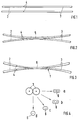
- Fig. 1
- zwei parallel nebeneinander liegende polarisationserhaltende Faserenden, die mit je einem Faserende von zwei nicht doppelbrechenden Einmodenfasern verspleißt sind, vor der Herstellung des Verschmelzkopplers;
- Fig. 2
- die Fasern der Fig. 1, während der Herstellung des Verschmelzkopplers;
- Fig. 3
- die Fasern der Fig. 2, nach der Herstellung des Verschmelzkopplers;
- Fig. 4a bis Fig. 4b
- mehrere Querschnittskonfigurationen des Verschmelzbereiches verschiedener Koppler.
- Fig. 1
- two polarization-maintaining fiber ends lying next to one another, which are spliced to one fiber end each of two non-birefringent single-mode fibers, before the fusion coupler is manufactured;
- Fig. 2
- the fibers of Figure 1 during the manufacture of the fusion coupler.
- Fig. 3
- 2, after the fusion coupler has been manufactured;
- 4a to 4b
- several cross-sectional configurations of the fusion area of different couplers.
In Fig. 1 sind die Eingangsfasern des herzustellenden Verschmelzkopplers 1 im folgenden kurz Koppler genannt mit 2 bezeichnet. Es handelt sich um polarisationserhaltende Einmodenfasern, deren Enden mit je einem Ende einer normalen, nicht doppelbrechenden Einmodenfaser vom Typ matched cladding durch Spleißen verbunden sind. Bei den Spleißen handelt es sich vorzugsweise um Verbindungen, die in bekannter Weise durch stoffschlüssiges Verschmelzen der Faserenden hergestellt werden. Die nicht doppelbrechenden Einmodenfasern bilden nach der Herstellung des Kopplers 1 die Ausgangsfasern 3, welche zugleich die Anschlußfasern darstellen. Nach Herstellung der Spleißverbindungen 4 wird das Faserpaar so in einer Ziehvorrichtung (nicht dargestellt) fixiert, daß die optischen Hauptachsen der polarisationserhaltenden Einmodenfasern (Eingangsfasern 2) parallel und senkrecht zur Kopplerachse liegen und die nicht doppelbrechenden Einmodenfasern (Ausgangsfasern 3) in einem Bereich, der einen relativ kurzen Abstand zu den Spleißverbindungen 4 hat parallel aneinanderliegen, wobei die Fasern im Querschnitt unverändert sind. Anschließend wird in eine der Eingangsfasern 2 Licht eingekoppelt und am Ende beider Ausgangsfasern 3 detektiert. Danach werden die nicht doppelbrechenden Einmodenfasern an der Berührungsstelle 5 (Fig. 2) miteinander verschmolzen und der Koppler 1 gleichzeitig in axialer Richtung ausgezogen, wobei die Fasern bikonisch getapert werden. Dabei erfolgt das Überkoppeln des Lichtes schon bei kurzen Ziehlängen. Um eine hohe Trennung der Polarisationsrichtungen zu erhalten, genügt bereits eine Ziehlänge von 10 mm bis 15 mm. Vorzugsweise beträgt die Ziehlänge ca. 11 mm bis 13 mm. Die Ziehlänge ist damit in vorteilhafter Weise nur unwesentlich länger als die von wellenlängenselektiven Schmelzkopplern.In FIG. 1, the input fibers of the
Fig. 3 zeigt den fertig ausgezogenen Koppler 1 mit dem erstarrten Verschmelzbereich 6, der aus den miteinander verschmolzenen Teilstücken der Ausgangsfasern 3 besteht und der die optischen Eigenschaften des Kopplers bestimmt. Je nach den gewünschten Eigenschaften wird vom Ausgangsquerschnitt der Einmodenfasern gemäß Fig. 4 her ein Schmelzbereich 6 geschaffen, der entsprechend
- Fig. 4a
- einen geringen Verschmelzungsgrad aufweist, bei dem die Mantelflächen der nicht doppelbrechenden Einmodenfasern nur linienförmig miteinander verbunden sind;
- Fig. 4b
- einen mittleren Verschmelzungsgrad aufweist, bei dem die Mantelflächen zwischen den nicht doppelbrechenden Einmodenfasern nur noch eine geringe Einschnürung haben;
- Fig. 4c
- einen hohen Verschmelzungsgrad mit elliptischem Querschnitt aufweist;
- Fig. 4d
- einen extremen Verschmelzungsgrad mit annähernd kreisrundem Querschnitt aufweist.
- Fig. 4a
- has a low degree of fusion, in which the lateral surfaces of the non-birefringent single-mode fibers are connected to one another only in a linear manner;
- Fig. 4b
- has an average degree of fusion, in which the lateral surfaces between the non-birefringent single-mode fibers have only a slight constriction;
- Fig. 4c
- has a high degree of fusion with an elliptical cross-section;
- Fig. 4d
- has an extreme degree of fusion with an approximately circular cross-section.
Der vorzugsweise mit einem mittleren Verschmelzungsgrad hergestellte Koppler 1 (Fig. 4b) zeigt für linear polarisiertes Licht (senkrecht oder parallel zur Kopplerebene) die Wellenlängenabhängigkeit eines wellenlängenselektiven Verschmelzkopplers. In der Wellenlängenabhängigkeit der beiden Polarisationsrichtungen besteht eine Phasenverschiebung von 180°. Die Übersprechdämpfung zwischen den beiden Polarisationsrichtungen (senkrecht und parallel zur Kopplerebene) beträgt in einem relativ großen nutzbaren Wellenlängenbereich ca. 19 dB bis 25 dB, während der Polarisationsgrad in den abgehenden Fasern (Ausgangsfasern 3) ebenfalls sehr hoch ist und Extinktionswerte von ca. 25 dB bis 30 dB erreicht. Dieser Koppler 1 mit nicht doppelbrechenden Einmodenfasern vereinigt somit die Eigenschaften von zwei Kopplern, wie sie in der DE-OS 37 16 247.0 von K. Fußgänger für ein Übertragungssystem mit Wellenlängen- und Polarisations-Multiplex vorgeschlagen worden sind.The coupler 1 (FIG. 4b), which is preferably manufactured with a medium degree of fusion, shows the wavelength dependence of a wavelength-selective fusion coupler for linearly polarized light (perpendicular or parallel to the coupler plane). There is a phase shift of 180 ° in the wavelength dependence of the two polarization directions. The crosstalk attenuation between the two polarization directions (perpendicular and parallel to the coupler plane) is approximately 19 dB to 25 dB in a relatively large usable wavelength range, while the degree of polarization in the outgoing fibers (output fibers 3) is also very high and Absorbance values of approx. 25 dB to 30 dB reached. This
Der Wellenlängenabstand benachbarter Kanäle beträgt bei dem Koppler 1 etwa 50 nm. Am 3dB-Punkt, bei dem in beiden Kanälen gleich viel Licht vorhanden ist, zeigt der Koppler 1 keine Polarisationsselektivität. 25 nm weiter, bei größerer oder kleinerer Wellenlänge, ist maximale Polariationsselektivität vorhanden. Dies wird dazu benutzt, um den polarisationsselektiven Koppler 1 zu optimieren. Wird der Koppler 1 z.B. bei einer Wellenlänge von 1530 nm benötigt, dann wird linear polarisiertes Licht von der Wellenlänge 1505 nm in eine Eingangsfaser 2 eingekoppelt. Durch Zufuhr von Wärme wird der Schmelzvorgang eingeleitet. Beim Verschmelzvorgang koppelt das Licht während des Ziehens zur anderen Faser über, dann wieder zurück, usw., wobei mit zunehmender Ziehlänge das Licht immer weniger vollständig überkoppelt. Der Ziehprozeß wird dann gestoppt, wenn das wechselseitige Überkoppeln stagniert und damit in beiden Kanälen gleichviel Licht vorhanden ist. Die Licht- und Wärmequellen werden den abgeschaltet, der Koppler 1 mit den Anschlußfasern aus der Ziehvorrichtung genommen und anschließend in einem Gehäuse mechanisch geschützt befestigt. Dies geschieht vorzugsweise so, daß die vom Verschmelzbereich 6 zu einer Anschlußfaser führenden Fasern unter Einschluß der Spleißverbindungen 4 krümmungsfrei im Kopplergehäuse liegen und darin festgelegt sind. Auf diese Weise sind die Anschlußfasern (Eingangs-/Ausgangsfasern 2, 3) zugentlastet gehalten.The wavelength spacing of adjacent channels in the
Der so angefertigte polarisationsselektive Koppler 1 hat sehr gute Eigenschaften. Außer einer relativ kurzen Baulänge zeichnet er sich durch sehr geringe Einfügeverluste aus, die weniger als 0,5 dB betragen. Er kann verwendet werden, um zwei Laser gleicher Wellenlänge an eine Faser anzukoppeln ("Laserredundanz", z.B. bei Unterwasserverstärkern) . Dazu wird das polarisierte Licht des einen Lasers parallel, das des anderen senkrecht zur Kopplerebene eingekoppelt. In diesem Fall erfolgt im Koppler eine Zusammenführung des Laserlichtes auf eine Standard-Einmodenfaser. Um dies zu gewährleisten, werden zwischen Laser und Koppler 1 die polarisationserhaltenden Fasern (Eingangsfasern 2) verwendet. Andernfalls wären Intensitätsschwankungen vorhanden, die zu einem Rauschen führen würden ("Polarisationsrauschen"). Die Aufteilung des ankommenden Laserlichtes in zueinander senkrechte Komponenten gestattet es, den Koppler für den Polarisationsdiversity-Empfang zu benutzen.The polarization-
Bei verschiedener Wellenlänge und unterschiedlicher Polarisation wird im Koppler 1 sowohl die Wellenlänge als auch die Polarisation aufgeteilt, wodurch eine hohe Fernnebensprechdämpfung gewährleistet wird.In the case of different wavelengths and different polarizations, both the wavelength and the polarization are divided in the
Claims (9)
- Process for manufacturing a polarization-selective optical fusion coupler (1), that has several input fibres (2) and output fibres (3) and in the coupling region consists of two parallel, non-birefringent monomode fibres with matched cladding, which are fused together under the action of heat and whose resulting fusion zone (6) is drawn out in the axial direction until the heat source is switched off, characterised in that input fibres (2) comprising polarization-maintaining fibres are first spliced to output fibres (3) which comprise non-birefringent monomode fibres with matched cladding, that linearly polarized light with a selected wavelength is then injected into one of the input fibres (2) and is detected at the ends of two output fibres (3), that the output fibres (3) are then fused together and the coupler (1) is drawn out until the mutual cross-coupling between the two output fibres (3) stagnates, and that the heat source is then switched off.
- Polarization-selective optical fused coupler manufactured by the process according to Claim 1, which has several polarization-maintaining input fibres, as well as non-birefringent, monomode fibres with matched cladding as output fibres which are spliced together, the output fibres in the coupling region being in parallel and fused together and drawn out, and the length of the fusion zone (1) being 10 mm to 15 mm.
- Coupler according to Claim 2, whereby polarization-maintaining monomode fibres (input fibres 2) have main optical axes parallel and perpendicular to the coupling plane.
- Coupler according to Claim 2, whereby the fibres leading from the fusion zone (6) to an input or output fibre (2, 3) lie without curvature in a coupler housing and are fixed in the coupler housing along with the spliced connections (4).
- Coupler according to Claim 2, whereby the coupler is polarization-selective for light of specific wavelength bands.
- Coupler according to Claim 2, whereby the coupler is wavelength-selective for light of a polarization direction which is parallel or perpendicular to the plane of the coupler.
- Coupler according to Claim 2, whereby the coupler has almost the same wavelength sensitivity to light of a polarization direction parallel to the plane of the coupler and to light of a polarization direction perpendicular to the plane of the coupler, a phase shift of 180° existing between the two polarization directions.
- Coupler according to Claim 2, whereby the coupler is polarization-selective and wavelength-selective at two different wavelengths.
- Coupler according to Claims 2 to 8, whereby in the fusion zone (6) the monomode fibres (output fibres 3) have an average degree of fusion, with lateral surfaces which have only a slight constriction (similar to Fig. 4b).
Applications Claiming Priority (2)
| Application Number | Priority Date | Filing Date | Title |
|---|---|---|---|
| DE3930035A DE3930035A1 (en) | 1989-09-08 | 1989-09-08 | METHOD FOR PRODUCING AN OPTICAL FUSION COUPLER AND COUPLER THEREFORE PRODUCED |
| DE3930035 | 1989-09-08 |
Publications (3)
| Publication Number | Publication Date |
|---|---|
| EP0416640A2 EP0416640A2 (en) | 1991-03-13 |
| EP0416640A3 EP0416640A3 (en) | 1992-01-22 |
| EP0416640B1 true EP0416640B1 (en) | 1996-11-27 |
Family
ID=6389005
Family Applications (1)
| Application Number | Title | Priority Date | Filing Date |
|---|---|---|---|
| EP90117241A Expired - Lifetime EP0416640B1 (en) | 1989-09-08 | 1990-09-07 | Method of fabrication of a fused optical coupler and coupler manufactured accordingly |
Country Status (8)
| Country | Link |
|---|---|
| US (1) | US5064267A (en) |
| EP (1) | EP0416640B1 (en) |
| JP (1) | JPH03100604A (en) |
| AT (1) | ATE145636T1 (en) |
| AU (1) | AU632359B2 (en) |
| DE (2) | DE3930035A1 (en) |
| DK (1) | DK0416640T3 (en) |
| ES (1) | ES2097123T3 (en) |
Families Citing this family (11)
| Publication number | Priority date | Publication date | Assignee | Title |
|---|---|---|---|---|
| DE3930029A1 (en) * | 1989-09-08 | 1991-03-21 | Standard Elektrik Lorenz Ag | METHOD FOR PRODUCING AN OPTICAL FUSION COUPLER |
| DE4109982A1 (en) * | 1991-03-27 | 1992-10-01 | Standard Elektrik Lorenz Ag | METHOD FOR PRODUCING AN OPTICAL MERGE COUPLER |
| US6701046B1 (en) * | 1999-09-30 | 2004-03-02 | Corning O.T.I. Spa | Method for producing an optical coupler for extracting a signal from a polarization maintaining optical fiber, and corresponding coupler |
| CA2289962C (en) * | 1999-11-17 | 2006-01-17 | Itf Optical Technologies Inc.-Technologies Optiques Itf Inc. | Fabrication of multiplexing and demultiplexing single-mode fiber optic couplers |
| KR100358418B1 (en) * | 2000-02-28 | 2002-10-25 | 한국과학기술원 | Method of fabricating fused-type mode selective coupler |
| US6813414B1 (en) * | 2000-07-17 | 2004-11-02 | Finisar Corporation | Fiber optical pigtail geometry for improved extinction ratio of polarization maintaining fibers |
| CA2354903C (en) | 2001-08-08 | 2008-10-14 | Itf Technologies Optiques Inc./Itf Optical Technologies Inc. | Polarization-combining fused-fiber optical coupler and method of producing the same |
| CA2465602C (en) * | 2003-09-29 | 2009-09-22 | Accelink Technologies Co., Ltd. | Variable polarization independent optical power splitter |
| JP2008076685A (en) * | 2006-09-20 | 2008-04-03 | National Institute Of Advanced Industrial & Technology | End-face proximity multicore optical fiber and manufacturing method thereof |
| DE102012110203A1 (en) * | 2012-10-25 | 2014-04-30 | Deutsches Zentrum für Luft- und Raumfahrt e.V. | Method for manufacturing optical cable having several glass fiber strands, involves adding supplementary glass fiber strands by local melting of surface layers close to second portions of arranged glass fiber strands |
| CN104749988B (en) | 2013-12-26 | 2017-12-05 | 同方威视技术股份有限公司 | Optoelectronic switch for object detection |
Citations (1)
| Publication number | Priority date | Publication date | Assignee | Title |
|---|---|---|---|---|
| EP0246737A2 (en) * | 1986-05-23 | 1987-11-25 | Nortel Networks Corporation | Directional coupler |
Family Cites Families (10)
| Publication number | Priority date | Publication date | Assignee | Title |
|---|---|---|---|---|
| US4360248A (en) * | 1979-04-18 | 1982-11-23 | International Telephone And Telegraph Corporation | Multiport optical communication system and optical star structure therefor |
| US4737005A (en) * | 1982-12-17 | 1988-04-12 | The United States Of America As Represented By The Secretary Of The Navy | Method for eliminating birefringence in a fiber optic coupler and a coupler polarization corrector |
| USRE33296E (en) * | 1983-05-26 | 1990-08-14 | Gould Inc. | Method of making a polarization-insensitive, evanescent-wave, fused coupler with minimal environmental sensitivity |
| US4743497A (en) * | 1985-08-08 | 1988-05-10 | Phillips Petroleum Company | Laminated puncture sealing composite and preparation thereof |
| US4834481A (en) * | 1985-11-12 | 1989-05-30 | Gould Inc. | In-line single-mode fiber optic multiplexer/demultiplexer |
| JPS63175812A (en) * | 1987-01-17 | 1988-07-20 | Nippon Telegr & Teleph Corp <Ntt> | Production of optical fiber coupler |
| DE3716247C2 (en) * | 1987-05-15 | 1994-04-28 | Sel Alcatel Ag | Optical communication system with wavelength and polarization multiplex |
| US4906068A (en) * | 1988-09-01 | 1990-03-06 | Minnesota Mining And Manufacturing Company | Polarization-maintaining optical fibers for coupler fabrication |
| US4932740A (en) * | 1989-06-05 | 1990-06-12 | Corning Incorporated | Method of making polarization retaining optical fiber coupler |
| DE3930029A1 (en) * | 1989-09-08 | 1991-03-21 | Standard Elektrik Lorenz Ag | METHOD FOR PRODUCING AN OPTICAL FUSION COUPLER |
-
1989
- 1989-09-08 DE DE3930035A patent/DE3930035A1/en not_active Withdrawn
-
1990
- 1990-08-31 AU AU62031/90A patent/AU632359B2/en not_active Ceased
- 1990-09-07 ES ES90117241T patent/ES2097123T3/en not_active Expired - Lifetime
- 1990-09-07 DK DK90117241.1T patent/DK0416640T3/en active
- 1990-09-07 AT AT90117241T patent/ATE145636T1/en not_active IP Right Cessation
- 1990-09-07 EP EP90117241A patent/EP0416640B1/en not_active Expired - Lifetime
- 1990-09-07 DE DE59010579T patent/DE59010579D1/en not_active Expired - Fee Related
- 1990-09-10 US US07/580,920 patent/US5064267A/en not_active Expired - Fee Related
- 1990-09-10 JP JP2239780A patent/JPH03100604A/en active Pending
Patent Citations (1)
| Publication number | Priority date | Publication date | Assignee | Title |
|---|---|---|---|---|
| EP0246737A2 (en) * | 1986-05-23 | 1987-11-25 | Nortel Networks Corporation | Directional coupler |
Also Published As
| Publication number | Publication date |
|---|---|
| ATE145636T1 (en) | 1996-12-15 |
| ES2097123T3 (en) | 1997-04-01 |
| AU632359B2 (en) | 1992-12-24 |
| EP0416640A2 (en) | 1991-03-13 |
| EP0416640A3 (en) | 1992-01-22 |
| US5064267A (en) | 1991-11-12 |
| DE3930035A1 (en) | 1991-03-21 |
| JPH03100604A (en) | 1991-04-25 |
| DK0416640T3 (en) | 1997-04-28 |
| AU6203190A (en) | 1991-03-14 |
| DE59010579D1 (en) | 1997-01-09 |
Similar Documents
| Publication | Publication Date | Title |
|---|---|---|
| DE69800007T2 (en) | Device with cascaded Raman fiber laser | |
| DE69132794T2 (en) | Optical communication systems with coaxial coupler | |
| DE69120402T2 (en) | Fiber optic amplifier with filter | |
| DE69838840T2 (en) | Active optical waveguide with asymetric polarization, its method of preparation and its use. | |
| DE69131615T2 (en) | MINIATURE FIBER OPTICAL BENDING DEVICE AND METHOD | |
| DE3782537T2 (en) | ALIGNMENT COUPLER. | |
| DE69404110T2 (en) | Amplifier with fiber filter pump system | |
| EP0390002B1 (en) | Optical-communication transmission system for diplex or duplex transmission | |
| CH644975A5 (en) | OPTICAL FIBER DIRECTIONAL COUPLER AND THEIR USE IN A TRANSMITTER / RECEIVER. | |
| EP0012189B1 (en) | Coupling device for separating a fraction of light from an optical waveguide comprising a jacketed core | |
| DE2729008A1 (en) | OPTICAL WAVE CONDUCTOR ARRANGEMENT | |
| DE2745940A1 (en) | OPTICAL CIRCUIT ELEMENT | |
| DE3221836C2 (en) | SINGLE FASHION FIBER | |
| EP0622649A1 (en) | Optical coupler with tap | |
| DE2851667C2 (en) | ||
| EP0265918B1 (en) | Optical broad band communication transmission system, especially in the subscriber access area | |
| EP0416640B1 (en) | Method of fabrication of a fused optical coupler and coupler manufactured accordingly | |
| DE69731252T2 (en) | Transmission system with low-cost optical filter | |
| DE19700682C2 (en) | Optical add / drop circuit with fiber optic grating | |
| DE69122766T2 (en) | OPTICAL NETWORK | |
| DE69808111T2 (en) | OPTICAL COUPLER AND / OR MULTIPLEXER | |
| EP0287925B1 (en) | Fibre-optical star coupler | |
| DE69014493T2 (en) | Fiber optic coupler. | |
| EP0048855A2 (en) | Element for adjusting the transfer of light between light guides | |
| EP0505828A1 (en) | Method for the fabrication of an optical fusion-coupler |
Legal Events
| Date | Code | Title | Description |
|---|---|---|---|
| PUAI | Public reference made under article 153(3) epc to a published international application that has entered the european phase |
Free format text: ORIGINAL CODE: 0009012 |
|
| AK | Designated contracting states |
Kind code of ref document: A2 Designated state(s): AT BE CH DE DK ES FR GB IT LI NL SE |
|
| PUAL | Search report despatched |
Free format text: ORIGINAL CODE: 0009013 |
|
| AK | Designated contracting states |
Kind code of ref document: A3 Designated state(s): AT BE CH DE DK ES FR GB IT LI NL SE |
|
| 17P | Request for examination filed |
Effective date: 19920613 |
|
| RAP3 | Party data changed (applicant data changed or rights of an application transferred) |
Owner name: ALCATEL N.V. Owner name: ALCATEL SEL AKTIENGESELLSCHAFT |
|
| 17Q | First examination report despatched |
Effective date: 19940816 |
|
| GRAG | Despatch of communication of intention to grant |
Free format text: ORIGINAL CODE: EPIDOS AGRA |
|
| GRAH | Despatch of communication of intention to grant a patent |
Free format text: ORIGINAL CODE: EPIDOS IGRA |
|
| GRAH | Despatch of communication of intention to grant a patent |
Free format text: ORIGINAL CODE: EPIDOS IGRA |
|
| GRAA | (expected) grant |
Free format text: ORIGINAL CODE: 0009210 |
|
| AK | Designated contracting states |
Kind code of ref document: B1 Designated state(s): AT BE CH DE DK ES FR GB IT LI NL SE |
|
| REF | Corresponds to: |
Ref document number: 145636 Country of ref document: AT Date of ref document: 19961215 Kind code of ref document: T |
|
| REG | Reference to a national code |
Ref country code: CH Ref legal event code: NV Representative=s name: JUERG ULRICH C/O ALCATEL STR AG |
|
| GBT | Gb: translation of ep patent filed (gb section 77(6)(a)/1977) |
Effective date: 19961127 |
|
| ITF | It: translation for a ep patent filed | ||
| REF | Corresponds to: |
Ref document number: 59010579 Country of ref document: DE Date of ref document: 19970109 |
|
| ET | Fr: translation filed | ||
| REG | Reference to a national code |
Ref country code: ES Ref legal event code: FG2A Ref document number: 2097123 Country of ref document: ES Kind code of ref document: T3 |
|
| REG | Reference to a national code |
Ref country code: DK Ref legal event code: T3 |
|
| PGFP | Annual fee paid to national office [announced via postgrant information from national office to epo] |
Ref country code: GB Payment date: 19970811 Year of fee payment: 8 |
|
| PGFP | Annual fee paid to national office [announced via postgrant information from national office to epo] |
Ref country code: SE Payment date: 19970820 Year of fee payment: 8 Ref country code: FR Payment date: 19970820 Year of fee payment: 8 Ref country code: DK Payment date: 19970820 Year of fee payment: 8 |
|
| PGFP | Annual fee paid to national office [announced via postgrant information from national office to epo] |
Ref country code: NL Payment date: 19970821 Year of fee payment: 8 Ref country code: DE Payment date: 19970821 Year of fee payment: 8 |
|
| PGFP | Annual fee paid to national office [announced via postgrant information from national office to epo] |
Ref country code: AT Payment date: 19970822 Year of fee payment: 8 |
|
| PGFP | Annual fee paid to national office [announced via postgrant information from national office to epo] |
Ref country code: CH Payment date: 19970828 Year of fee payment: 8 Ref country code: BE Payment date: 19970828 Year of fee payment: 8 |
|
| PGFP | Annual fee paid to national office [announced via postgrant information from national office to epo] |
Ref country code: ES Payment date: 19970926 Year of fee payment: 8 |
|
| PLBE | No opposition filed within time limit |
Free format text: ORIGINAL CODE: 0009261 |
|
| STAA | Information on the status of an ep patent application or granted ep patent |
Free format text: STATUS: NO OPPOSITION FILED WITHIN TIME LIMIT |
|
| 26N | No opposition filed | ||
| PG25 | Lapsed in a contracting state [announced via postgrant information from national office to epo] |
Ref country code: GB Free format text: LAPSE BECAUSE OF NON-PAYMENT OF DUE FEES Effective date: 19980907 Ref country code: DK Free format text: LAPSE BECAUSE OF NON-PAYMENT OF DUE FEES Effective date: 19980907 Ref country code: AT Free format text: LAPSE BECAUSE OF NON-PAYMENT OF DUE FEES Effective date: 19980907 |
|
| PG25 | Lapsed in a contracting state [announced via postgrant information from national office to epo] |
Ref country code: SE Free format text: LAPSE BECAUSE OF NON-PAYMENT OF DUE FEES Effective date: 19980908 Ref country code: ES Free format text: LAPSE BECAUSE OF EXPIRATION OF PROTECTION Effective date: 19980908 |
|
| PG25 | Lapsed in a contracting state [announced via postgrant information from national office to epo] |
Ref country code: LI Free format text: LAPSE BECAUSE OF NON-PAYMENT OF DUE FEES Effective date: 19980930 Ref country code: CH Free format text: LAPSE BECAUSE OF NON-PAYMENT OF DUE FEES Effective date: 19980930 Ref country code: BE Free format text: LAPSE BECAUSE OF NON-PAYMENT OF DUE FEES Effective date: 19980930 |
|
| BERE | Be: lapsed |
Owner name: ALCATEL N.V. Effective date: 19980930 |
|
| PG25 | Lapsed in a contracting state [announced via postgrant information from national office to epo] |
Ref country code: NL Free format text: LAPSE BECAUSE OF NON-PAYMENT OF DUE FEES Effective date: 19990401 |
|
| GBPC | Gb: european patent ceased through non-payment of renewal fee |
Effective date: 19980907 |
|
| REG | Reference to a national code |
Ref country code: CH Ref legal event code: PL |
|
| EUG | Se: european patent has lapsed |
Ref document number: 90117241.1 |
|
| PG25 | Lapsed in a contracting state [announced via postgrant information from national office to epo] |
Ref country code: FR Free format text: LAPSE BECAUSE OF NON-PAYMENT OF DUE FEES Effective date: 19990531 |
|
| NLV4 | Nl: lapsed or anulled due to non-payment of the annual fee |
Effective date: 19990401 |
|
| PG25 | Lapsed in a contracting state [announced via postgrant information from national office to epo] |
Ref country code: DE Free format text: LAPSE BECAUSE OF NON-PAYMENT OF DUE FEES Effective date: 19990701 |
|
| REG | Reference to a national code |
Ref country code: FR Ref legal event code: ST |
|
| REG | Reference to a national code |
Ref country code: DK Ref legal event code: EBP |
|
| REG | Reference to a national code |
Ref country code: ES Ref legal event code: FD2A Effective date: 20010201 |
|
| PG25 | Lapsed in a contracting state [announced via postgrant information from national office to epo] |
Ref country code: IT Free format text: LAPSE BECAUSE OF NON-PAYMENT OF DUE FEES;WARNING: LAPSES OF ITALIAN PATENTS WITH EFFECTIVE DATE BEFORE 2007 MAY HAVE OCCURRED AT ANY TIME BEFORE 2007. THE CORRECT EFFECTIVE DATE MAY BE DIFFERENT FROM THE ONE RECORDED. Effective date: 20050907 |