EP0416265A1 - Method and device for controlling fuel injection - Google Patents
Method and device for controlling fuel injection Download PDFInfo
- Publication number
- EP0416265A1 EP0416265A1 EP19900114347 EP90114347A EP0416265A1 EP 0416265 A1 EP0416265 A1 EP 0416265A1 EP 19900114347 EP19900114347 EP 19900114347 EP 90114347 A EP90114347 A EP 90114347A EP 0416265 A1 EP0416265 A1 EP 0416265A1
- Authority
- EP
- European Patent Office
- Prior art keywords
- injection
- fuel
- solenoid valve
- duration
- adjustment signals
- Prior art date
- Legal status (The legal status is an assumption and is not a legal conclusion. Google has not performed a legal analysis and makes no representation as to the accuracy of the status listed.)
- Granted
Links
Images
Classifications
-
- F—MECHANICAL ENGINEERING; LIGHTING; HEATING; WEAPONS; BLASTING
- F02—COMBUSTION ENGINES; HOT-GAS OR COMBUSTION-PRODUCT ENGINE PLANTS
- F02D—CONTROLLING COMBUSTION ENGINES
- F02D41/00—Electrical control of supply of combustible mixture or its constituents
- F02D41/30—Controlling fuel injection
- F02D41/38—Controlling fuel injection of the high pressure type
- F02D41/40—Controlling fuel injection of the high pressure type with means for controlling injection timing or duration
- F02D41/402—Multiple injections
- F02D41/403—Multiple injections with pilot injections
-
- F—MECHANICAL ENGINEERING; LIGHTING; HEATING; WEAPONS; BLASTING
- F02—COMBUSTION ENGINES; HOT-GAS OR COMBUSTION-PRODUCT ENGINE PLANTS
- F02D—CONTROLLING COMBUSTION ENGINES
- F02D35/00—Controlling engines, dependent on conditions exterior or interior to engines, not otherwise provided for
- F02D35/02—Controlling engines, dependent on conditions exterior or interior to engines, not otherwise provided for on interior conditions
- F02D35/023—Controlling engines, dependent on conditions exterior or interior to engines, not otherwise provided for on interior conditions by determining the cylinder pressure
-
- F—MECHANICAL ENGINEERING; LIGHTING; HEATING; WEAPONS; BLASTING
- F02—COMBUSTION ENGINES; HOT-GAS OR COMBUSTION-PRODUCT ENGINE PLANTS
- F02D—CONTROLLING COMBUSTION ENGINES
- F02D41/00—Electrical control of supply of combustible mixture or its constituents
- F02D41/24—Electrical control of supply of combustible mixture or its constituents characterised by the use of digital means
- F02D41/2406—Electrical control of supply of combustible mixture or its constituents characterised by the use of digital means using essentially read only memories
- F02D41/2425—Particular ways of programming the data
- F02D41/2429—Methods of calibrating or learning
- F02D41/2451—Methods of calibrating or learning characterised by what is learned or calibrated
- F02D41/2464—Characteristics of actuators
- F02D41/2467—Characteristics of actuators for injectors
- F02D41/247—Behaviour for small quantities
-
- F—MECHANICAL ENGINEERING; LIGHTING; HEATING; WEAPONS; BLASTING
- F02—COMBUSTION ENGINES; HOT-GAS OR COMBUSTION-PRODUCT ENGINE PLANTS
- F02B—INTERNAL-COMBUSTION PISTON ENGINES; COMBUSTION ENGINES IN GENERAL
- F02B3/00—Engines characterised by air compression and subsequent fuel addition
- F02B3/06—Engines characterised by air compression and subsequent fuel addition with compression ignition
-
- F—MECHANICAL ENGINEERING; LIGHTING; HEATING; WEAPONS; BLASTING
- F02—COMBUSTION ENGINES; HOT-GAS OR COMBUSTION-PRODUCT ENGINE PLANTS
- F02D—CONTROLLING COMBUSTION ENGINES
- F02D41/00—Electrical control of supply of combustible mixture or its constituents
- F02D41/30—Controlling fuel injection
- F02D41/38—Controlling fuel injection of the high pressure type
- F02D41/40—Controlling fuel injection of the high pressure type with means for controlling injection timing or duration
- F02D41/402—Multiple injections
-
- Y—GENERAL TAGGING OF NEW TECHNOLOGICAL DEVELOPMENTS; GENERAL TAGGING OF CROSS-SECTIONAL TECHNOLOGIES SPANNING OVER SEVERAL SECTIONS OF THE IPC; TECHNICAL SUBJECTS COVERED BY FORMER USPC CROSS-REFERENCE ART COLLECTIONS [XRACs] AND DIGESTS
- Y02—TECHNOLOGIES OR APPLICATIONS FOR MITIGATION OR ADAPTATION AGAINST CLIMATE CHANGE
- Y02T—CLIMATE CHANGE MITIGATION TECHNOLOGIES RELATED TO TRANSPORTATION
- Y02T10/00—Road transport of goods or passengers
- Y02T10/10—Internal combustion engine [ICE] based vehicles
- Y02T10/40—Engine management systems
Definitions
- the invention relates to a method and a device for controlling fuel injection according to the preambles of the main claims.
- a method for controlling the fuel injection is known from DE-OS-37 20 544.
- a method for controlling the fuel injection of a high-pressure fuel pump is described there.
- the quantity of fuel to be injected into the internal combustion engine can be determined by means of a solenoid valve.
- the solenoid valve In the delivery phase of a pump element, the solenoid valve is selectively closed and opened so that a pre-injection and then a main injection are carried out. Due to manufacturing tolerances and signs of aging, there are variations in the amount of fuel injected into the individual cylinders of the internal combustion engine.
- the invention is based on the object of eliminating scatter in the injected fuel quantity in a method and a device for controlling the fuel injection of the type mentioned in the pre-injection. This object is achieved by the features characterized in the main claims.
- the method and device according to the invention have the advantage that the injected fuel quantity always has the same value for the same duration of the control signals for the pre-injection. This is achieved in that, in certain operating states, the duration of the control pulse for the solenoid valve is determined, during which a pre-injection is taking place.
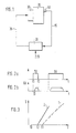
- Figure 1 shows a schematic representation of a device for performing the method according to claim 1.
- Figure 2 the control pulses for the pilot injection TV and the main injection TH are shown.
- Figure 3 shows the relationship between the duration of the drive pulse T and the injected fuel quantity QK.
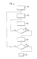
- a flow chart to explain the method is shown in FIG. 4.
- Figure 1 shows essential parts of a device for fuel injection into an internal combustion engine.
- the internal combustion engine 10 receives a certain amount of fuel from the fuel pump 30.
- Various sensors 40 record measured values 15 which characterize the operating state of the internal combustion engine and pass them to a control unit 20.
- the control unit 20 calculates, based on the measured values 15 and further variables 25, control pulses 35 with which the fuel pump 30 is acted upon.
- the internal combustion engine 10 is a self-igniting internal combustion engine.
- the control unit 20 calculates the amount of fuel to be injected into the internal combustion engine 10 in a known manner. This calculation is carried out depending on various measured values 15, e.g. Speed, engine temperature, actual start of injection and possibly other variables 25 that characterize the operating state of the internal combustion engine, these are e.g. the position of the accelerator pedal 25, the ambient air pressure.
- the control unit 20 then converts the desired fuel quantity into control pulses 35. These actuation pulses are then applied to the quantity-determining element of the fuel pump 30.
- a quantity-determining link e.g. serve a solenoid valve which is arranged so that the amount of fuel to be injected is determined by the opening or closing time of the solenoid valve.
- the solenoid valve is arranged, for example, in the high-pressure fuel pump in such a way that, during the delivery phase of the pump element, pressure builds up in the element space of the pump after the solenoid valve is closed, and the injection takes place automatically when a certain pressure value is exceeded. Opening the solenoid valve causes the Pressure in the element space and the injection is ended. By briefly closing and then opening the solenoid valve in the delivery phase of the pump element, a pre-injection can be achieved before the actual main injection.
- a separate high-pressure fuel pump with a solenoid valve that determines the fuel quantity to be injected can be provided for each cylinder, or a high-pressure fuel pump with a solenoid valve sequentially applies fuel to all cylinders.
- FIG. 2a shows a possible sequence of control pulses for a pre-injection TV and the subsequent main injection TH
- FIG. 2b shows the fuel quantity QK injected due to the control pulses shown in FIG. 2a over time t.
- FIGS. 2a and 2b show that the solenoid valve closes at time t1 and that fuel is injected after a short delay time t0. The solenoid valve opens at time t2 and the fuel supply ends.
- the control pulse for the pre-injection is significantly smaller than the control pulse for the main injection TH. Since solenoid valves can have different closing times for the same activation pulse, it can happen that different amounts of fuel are injected with the same duration of the activation pulse and otherwise the same operating parameters.
- control pulses for the pre-injection are usually very short, it can now occur that no pre-injection takes place for individual solenoid valves. On the other hand, however, it can also happen that the pilot injection becomes so large that the exhaust gas values of the internal combustion engine deteriorate.
- FIG. 3 shows the relationship between the duration of the drive pulse T and the injected fuel quantity Q for the solenoid valves 1 and 2.
- the solenoid valve 1 measures fuel in the event of a drive pulse of the time period T1.
- the Solenoid valves are supplied with a signal of duration T2, so pre-injection occurs only for solenoid valve 2, but not for solenoid valve 1.
- the aim of the method described below is to compensate for these variations. There are essentially two causes for this scattering, on the one hand there are tolerances in the manufacture of the solenoid valves and on the other hand there are signs of aging in the injection device. This process is particularly important in pump-nozzle systems.
- a method to compensate for these variations is now to be described with the aid of the flow chart of FIG.
- This method is not only limited to solenoid valve controlled fuel pumps, it can also be transferred to other electrically controlled signal boxes for high pressure fuel pumps at any time.
- a first step 100 it is checked whether the internal combustion engine is in an operating state in which the method can be carried out. These are preferably stationary operating points. However, it is also possible to initialize the process by means of a signal from an external control device. This is the case if the procedure is to be carried out in the factory by the engine manufacturer or as part of maintenance and possibly to be retained as the basic setting.
- the duration of the drive pulse is set to such a small value T0 that there is certainly no pre-injection.
- the drive pulses for the main injection are kept at a constant value in the following.
- the duration of the control pulse for the pre-injection is increased.
- the feedback signals like the operating parameters, are detected by suitable sensors 40. As feedback signals one or a combination of the signals from different sensors can be used in a particularly advantageous manner.
- Suitable sensors are sensors which detect the duration of the spray, the element pressure, the combustion chamber pressure, the engine structure-borne noise, the airborne noise, or a light signal in the combustion chamber. Possibly. the signals must be viewed in correlation with the control signal of the pilot injection. With a corresponding number of sensors, it is possible to consider each solenoid valve separately. If there is no feedback signal, the duration of the control pulse is increased further until a feedback signal is present. In the presence of a feedback signal, the duration of the actuation pulse is permanently stored 108 as an adjustment signal.
- the query unit 110 causes the procedure to be carried out for all cylinders. In step 120, the system jumps back to the main program for controlling the internal combustion engine, which is known per se.
- the procedure is carried out once in the factory at the engine manufacturer or as part of maintenance and is retained as the basic setting. Drifts over the term are compensated for in a controlled manner, depending on e.g. of the runtime weighted with speed and load. In operation, this procedure is carried out at stationary operating points. The adjustment signals are then used in the subsequent injection processes to adaptively improve the control of the pre-injection.
- the values determined with the aid of the method can be stored in a particularly advantageous manner in a map of load and speed and are then available for each pre-injection.
Landscapes
- Engineering & Computer Science (AREA)
- Chemical & Material Sciences (AREA)
- Combustion & Propulsion (AREA)
- Mechanical Engineering (AREA)
- General Engineering & Computer Science (AREA)
- Electrical Control Of Air Or Fuel Supplied To Internal-Combustion Engine (AREA)
- Combined Controls Of Internal Combustion Engines (AREA)
- Fuel-Injection Apparatus (AREA)
Abstract
Description
Die Erfindung betrifft ein Verfahren und eine Einrichtung zum Steuern der Kraftstoffeinspritzung gemäß den Oberbegriffen der Hauptansprüche. Ein solches Verfahren zum Steuern der Kraftstoffeinspritzung ist aus der DE-OS-37 20 544 bekannt. Dort wird ein Verfahren zum Steuern der Kraftstoffeinspritzung einer Hochdruckkraftstoffpumpe beschrieben. Mittels eines Magnetventils kann die in die Brennkraftmaschine einzuspritzende Kraftstoffmenge festgelegt werden. In der Förderphase eines Pumpenelements wird das Magnetventil selektiv geschlossen und geöffnet, so daß eine Voreinspritzung und anschließend eine Haupteinspritzung durchgeführt werden. Durch Fertigungstoleranzen und Alterungserscheinungen, treten Streuungen bei der in die einzelnen Zylinder der Brennkraftmaschine eingespritzten Kraftstoffmenge auf. Diese Streuungen bewirken, daß bei der Voreinspritzung bei gleichem Ansteuersignalder der Brennkraftmaschine unterschiedliche Mengen zugeführt werden. Da es sich bei den Voreinspritzmengen nur um sehr geringe Mengen handelt, kann der Fall eintreten, daß bei gleichem Ansteuersignal eine oder keine Voreinspritzung erfolgt. Dadurch gehen die Vorteile der Voreinspritzung verloren, d.h. es treten verstärkte Verbrennungsgeräusche auf.The invention relates to a method and a device for controlling fuel injection according to the preambles of the main claims. Such a method for controlling the fuel injection is known from DE-OS-37 20 544. A method for controlling the fuel injection of a high-pressure fuel pump is described there. The quantity of fuel to be injected into the internal combustion engine can be determined by means of a solenoid valve. In the delivery phase of a pump element, the solenoid valve is selectively closed and opened so that a pre-injection and then a main injection are carried out. Due to manufacturing tolerances and signs of aging, there are variations in the amount of fuel injected into the individual cylinders of the internal combustion engine. These scatterings mean that different amounts are supplied to the internal combustion engine during the pre-injection with the same control signal. Since the pre-injection quantities are only very small quantities, the case may occur that, with the same control signal, one or no pre-injection takes place. As a result, the advantages of pre-injection are lost, ie increased combustion noises occur.
Der Erfindung liegt die Aufgabe zugrunde, bei einem Verfahren und einer Einrichtung zum Steuern der Kraftstoffeinspritzung der eingangs genannten Art bei der Voreinspritzung Streuungen in der eingespritzten Kraftstoffmenge zu eliminieren. Diese Aufgabe wird durch die in den Hauptansprüchen gekennzeichneten Merkmale gelöst.The invention is based on the object of eliminating scatter in the injected fuel quantity in a method and a device for controlling the fuel injection of the type mentioned in the pre-injection. This object is achieved by the features characterized in the main claims.
Das erfindungsgemäße Verfahren und Einrichtung besitzt demgegenüber den Vorteil, daß bei gleicher Dauer der Ansteuersignale für die Voreinspritzung die eingespritzte Kraftstoffmenge immer den gleichen Wert besitzt. Dies wird dadurch erreicht, daß in bestimmten Betriebszuständen die Dauer des Ansteuerimpulses für das Magnetventil ermittelt wird, bei dem gerade eine Voreinspritzung erfolgt.The method and device according to the invention have the advantage that the injected fuel quantity always has the same value for the same duration of the control signals for the pre-injection. This is achieved in that, in certain operating states, the duration of the control pulse for the solenoid valve is determined, during which a pre-injection is taking place.
Vorteilhafte und zweckmäßige Ausgestaltungen und Weiterbildungen der Erfindung sind in den Unteransprüchen gekennzeichnet.Advantageous and expedient refinements and developments of the invention are characterized in the subclaims.
Die Erfindung wird nachstehend anhand der in den Zeichnungen dargestellten Ausführungsbeispielen erläutert. Figur 1 zeigt eine schematische Darstellung einer Einrichtung zur Durchführung des Verfahrens gemäß dem Anspruchs 1. In Figur 2 sind die Ansteuerimpulse für die Voreinspritzung TV und die Haupteinspritzung TH dargestellt. Figur 3 zeigt den Zusammenhang zwischen Dauer des Ansteuerimpulses T und der eingespritzten Kraftstoffmenge QK. Ein Flußdiagramm zur Erläuterung des Verfahrens ist in Figur 4 aufgeführt.The invention is explained below with reference to the embodiments shown in the drawings. Figure 1 shows a schematic representation of a device for performing the method according to claim 1. In Figure 2, the control pulses for the pilot injection TV and the main injection TH are shown. Figure 3 shows the relationship between the duration of the drive pulse T and the injected fuel quantity QK. A flow chart to explain the method is shown in FIG. 4.
Figur 1 zeigt wesentliche Teile einer Einrichtung zur Kraftstoffeinspritzung in eine Brennkraftmaschine. Der Brennkraftmaschine 10 erhält von der Kraftstoffpumpe 30 eine bestimmte Kraftstoffmenge zugemessen. Verschiedene Sensoren 40 erfassen Meßwerte 15 die den Betriebszustand der Brennkraftmaschine charakterisieren und leiten diese zu einem Steuergerät 20. Das Steuergerät 20 berechnet ausgehend von den Meßwerten 15 und weiteren Größen 25 Ansteuerimpulse 35, mit denen die Kraftstoffpumpe 30 beaufschlagt wird. Bei der Brennkraftmaschine 10 handelt es sich um eine selbstzündende Brennkraftmaschine.Figure 1 shows essential parts of a device for fuel injection into an internal combustion engine. The
Das Steuergerät 20 berechnet in bekannter Weise die in die Brennkraftmaschine 10 einzuspritzende Kraftstoffmenge. Diese Berechnung erfolgt abhängig von verschiedenen Meßwerten 15 wie z.B. Drehzahl, Motortemperatur, tatsächlichen Einspritzbeginn und evtl. noch weiteren Größen 25, die den Betriebszustand der Brennkraftmaschine charakterisieren, dies sind z.B. die Stellung des Fahrpedals 25, der Umgebungsluftdruck. Das Steuergerät 20 setzt dann die gewünschte Kraftstoffmenge in Ansteuerimpulse 35 um. Mit diesen Ansteuerimpulsen wird dann das mengenbestimmende Glied der Kraftstoffpumpe 30 beaufschlagt. Als mengenbestimmendes Glied kann z.B. ein Magnetventil dienen, das so angeordnet ist, daß durch die Öffnungsdauer, bzw. die Schließdauer des Magnetventils die einzuspritzende Kraftstoffmenge festgelegt wird.The
Das Magnetventil ist z.B. in der Hochdruckkraftstoffpumpe so angeordnet sein, daß während der Förderphase des Pumpenelements sich im Elementraum der Pumpe nach Schließen des Magnetventils Druck aufbaut, und bei Überschreiten eines bestimmten Druckwertes selbständig die Einspritzung erfolgt. Durch Öffnen des Magnetventils fällt der Druck im Elementraum ab und die Einspritzung wird beeendet. Durch kurzzeitiges Schließen und anschließendes Öffnen des Magnetventil in der Förderphase des Pumpenelements kann eine Voreinspritzung vor der eigentlichen Haupteinspritzung erzielt werden.The solenoid valve is arranged, for example, in the high-pressure fuel pump in such a way that, during the delivery phase of the pump element, pressure builds up in the element space of the pump after the solenoid valve is closed, and the injection takes place automatically when a certain pressure value is exceeded. Opening the solenoid valve causes the Pressure in the element space and the injection is ended. By briefly closing and then opening the solenoid valve in the delivery phase of the pump element, a pre-injection can be achieved before the actual main injection.
Dabei kann für jeden Zylinder eine separate Hochdruckkraftstoffpumpe mit einem die einzuspritzende Kraftstoffmenge bestimmenden Magnetventil vorhanden sein, oder eine Hochdruckkraftstoffpumpe mit einem Magnetventil beaufschlagt alle Zylinder nacheinander mit Kraftstoff.A separate high-pressure fuel pump with a solenoid valve that determines the fuel quantity to be injected can be provided for each cylinder, or a high-pressure fuel pump with a solenoid valve sequentially applies fuel to all cylinders.
Figur 2a zeigt eine mögliche Abfolge von Ansteuerimpulsen für eine Voreinspritzung TV und die nachfolgende Haupteinspritzung TH, Figur 2b die, aufgrund der in Figur 2a dargestellten Ansteuerimpulsen, eingespritzten Kraftstoffmenge QK über der Zeit t aufgetragen. Der Figur 2a und 2b ist zu entnehmen, daß zum Zeitpunkt t1 das Magnetventil schließt und nach einer kurzen Verzögerungszeit t0 Kraftstoff eingespritzt wird. Zum Zeitpunkt t2 öffnet das Magnetventil und damit endet die Kraftstoffzufuhr. Normalerweise ist der Ansteuerimpuls für die Voreinspritzung wesentlich kleiner als der Ansteuerimpuls für die Haupteinspritzung TH. Da Magnetventile bei gleichem Ansteuerimpuls unterschiedliche Schließzeiten besitzen können, kann es vorkommen, daß bei gleicher Zeitdauer des Ansteuerimpulses und sonst gleichen Betriebsparametern unterschiedliche Kraftstoffmengen eingespritzt werden. Da die Ansteuerimpulse für die Voreinspritzung üblicherweise sehr kurz sind, kann nun der Fall eintreten, daß bei einzelnen Magnetventilen keine Voreinspritzung erfolgt. Auf der anderen Seite kann aber auch der Fall eintreten, daß die Voreinspritzung so groß wird, daß sich die Abgaswerte der Brennkraftmaschine verschlechtern.FIG. 2a shows a possible sequence of control pulses for a pre-injection TV and the subsequent main injection TH, FIG. 2b shows the fuel quantity QK injected due to the control pulses shown in FIG. 2a over time t. FIGS. 2a and 2b show that the solenoid valve closes at time t1 and that fuel is injected after a short delay time t0. The solenoid valve opens at time t2 and the fuel supply ends. Normally, the control pulse for the pre-injection is significantly smaller than the control pulse for the main injection TH. Since solenoid valves can have different closing times for the same activation pulse, it can happen that different amounts of fuel are injected with the same duration of the activation pulse and otherwise the same operating parameters. Since the control pulses for the pre-injection are usually very short, it can now occur that no pre-injection takes place for individual solenoid valves. On the other hand, however, it can also happen that the pilot injection becomes so large that the exhaust gas values of the internal combustion engine deteriorate.
Figur 3 zeigt den Zusammenhang zwischen der Dauer des Ansteuerimpulses T und der eingespritzten Kraftstoffmenge Q für die Magnetventile 1 und 2. Das Magnetventil 1 mißt bei einem Ansteuerimpuls der Zeitdauer T1 Kraftstoff zu. Das Magnetventil 2 dagegen mißt schon bei einem Ansteuerimpuls der Dauer T2 Kraftstoff zu. Werden nun die Magnetventile mit einem Signal der Dauer T2 beaufschlagt, so erfolgt nur bei dem Magnetventil 2 eine Voreinspritzung, bei Magnetventil 1 dagegen nicht.FIG. 3 shows the relationship between the duration of the drive pulse T and the injected fuel quantity Q for the solenoid valves 1 and 2. The solenoid valve 1 measures fuel in the event of a drive pulse of the time period T1. The solenoid valve 2, on the other hand, already measures fuel in the case of a control pulse of duration T2. Now are the Solenoid valves are supplied with a signal of duration T2, so pre-injection occurs only for solenoid valve 2, but not for solenoid valve 1.
Ziel des im folgenden beschriebenen Verfahren ist es nun diese Streuungen auszugleichen. Dabei sind im wesentlichen zwei Ursachen für diese Streuungen gegeben, dies sind zum einen Toleranzen bei der Fertigung der Magnetventile, zum andern Alterungserscheinungen in der Einspritzeinrichtung. Von besonderer Bedeutung ist dieses Verfahren bei Pumpe-Düse-Systemen.The aim of the method described below is to compensate for these variations. There are essentially two causes for this scattering, on the one hand there are tolerances in the manufacture of the solenoid valves and on the other hand there are signs of aging in the injection device. This process is particularly important in pump-nozzle systems.
Mit Hilfe des Flußdiagrammes von Figur 4 soll nun ein Verfahren zum Ausgleich dieser Streuungen beschrieben werden. Dieses Verfahren ist dabei nicht nur auf magnetventilgesteuerte Kraftstoffpumpen beschränkt, es kann jederzeit auch auf andere elektrisch gesteuerte Stellwerke für Hochdruckkraftstoffpumpen übertragen werden. In einem ersten Schritt 100 wird überprüft ob sich die Brennkraftmaschine in einem Betriebszustand befindet in dem das Verfahren durchgeführt werden kann. Dies sind vorzugsweise stationäre Betriebspunkte. Es ist aber auch möglich durch ein Signal von einem externen Steuergerät das Verfahren zu initialisieren. Dies ist der Fall, wenn das Verfahren im Werk beim Motorenhersteller oder im Rahmen der Wartung durchgeführt und eventuel als Grundeinstellung beibehalten werden soll. Im Initialisierungsschritt 102 wird die Dauer des Ansteuerimpulses auf ein solch kleinen Wert T0 gesetzt, daß sicher keine Voreinspritzung erfolgt. Die Ansteuerimpulse für die Haupteinspritzung werden im folgenden auf einen konstanten Wert gehalten. In einem weiteren Schritt 104 erfolgt eine Erhöhung der Dauer des Ansteuerimpulses für die Voreinspritzung. Im Schritt 106 wird dann überprüft, ob ein Rückmeldesignal sich verändert hat. Anhand der Anderung des Rückmeldesignals kann erkannt werden, ob eine Voreinspritzung erfolgte oder nicht. Ändert sich das Rückmeldesignal nicht, so erfolgte keine Voreinspritzung. Ändert sich dagegen das Rückmeldesignal bei konstanter Haupteinspritzung so erfolgt eine Voreinspritzung. Die Rückmeldesignale werden ebenfalls wie die Betriebskenngrößen durch geeignete Sensoren 40 erfaßt. Als Rückmeldesignale können in besonders vorteilhafter Weise eines oder eine Kombination aus den Signalen verschiedener Sensoren verwendet werden. Als Sensoren kommen Sensoren die die Spritzdauer, den Elementdruck, den Brennraumdruck, den Motorkörperschall, den Luftschall, oder ein Lichtsignal im Brennraum erfassen in Frage. Evtl. müssen die Signale in Korrelation mit dem Ansteuersignal der Voreinspritzung betrachtet werden. Es ist dabei möglich, bei einer entsprechenden Anzahl von Sensoren, jedes Magnetventil separat zu betrachten. Ist kein Rückmeldesignal vorhanden, so erfolgt eine weitere Erhöhung der Dauer des Ansteuerimpulses, bis ein Rückmeldesignal vorhanden ist. Bei Vorhandensein eines Rückmeldesignals wird die Dauer des Ansteuerimpulses als Abgleichsignal dauerhaft abgespeichert 108. Die Abfrageeinheit 110 veranlaßt, daß die Prozedur für alle Zylinder durchgeführt wird. Im Schritt 120 erfolgt der Rücksprung in das an sich bekannte Hauptprogramm zur Steuerung der Brennkraftmaschine.A method to compensate for these variations is now to be described with the aid of the flow chart of FIG. This method is not only limited to solenoid valve controlled fuel pumps, it can also be transferred to other electrically controlled signal boxes for high pressure fuel pumps at any time. In a
Es sind im wesentlichen die folgenden Strategien zur Durchführung des Verfahrens denkbar. Das Verfahren wird einmal im Werk beim Motorenhersteller oder im Rahmen der Wartung durchgeführt und als Grundeinstellung beibehalten. Driften über die Laufzeit werden gesteuert kompensiert, abhängig z.B. von der mit Drehzahl und Last gewichteten Laufzeit. Im Betrieb wird bei stationären Betriebspunkten dieses Verfahren durchgeführt. Die Abgleichsignale werden dann bei den folgenden Einspritzvorgängen zur adaptiven Verbesserung der Steuerung der Voreinspritzung verwendet.The following strategies for carrying out the method are essentially conceivable. The procedure is carried out once in the factory at the engine manufacturer or as part of maintenance and is retained as the basic setting. Drifts over the term are compensated for in a controlled manner, depending on e.g. of the runtime weighted with speed and load. In operation, this procedure is carried out at stationary operating points. The adjustment signals are then used in the subsequent injection processes to adaptively improve the control of the pre-injection.
Die mit Hilfe des Verfahrens ermittelten Werte können in besonders vorteilhafter Weise in einem Kennfeld über Last und Drehzahl gespeichert werden und stehen dann bei jeder Voreinspritzung zur Verfügung.The values determined with the aid of the method can be stored in a particularly advantageous manner in a map of load and speed and are then available for each pre-injection.
Claims (10)
Applications Claiming Priority (2)
| Application Number | Priority Date | Filing Date | Title |
|---|---|---|---|
| DE3929747 | 1989-09-07 | ||
| DE3929747A DE3929747A1 (en) | 1989-09-07 | 1989-09-07 | METHOD AND DEVICE FOR CONTROLLING FUEL INJECTION |
Publications (2)
| Publication Number | Publication Date |
|---|---|
| EP0416265A1 true EP0416265A1 (en) | 1991-03-13 |
| EP0416265B1 EP0416265B1 (en) | 1992-12-30 |
Family
ID=6388831
Family Applications (1)
| Application Number | Title | Priority Date | Filing Date |
|---|---|---|---|
| EP90114347A Expired - Lifetime EP0416265B1 (en) | 1989-09-07 | 1990-07-26 | Method and device for controlling fuel injection |
Country Status (4)
| Country | Link |
|---|---|
| US (1) | US5070836A (en) |
| EP (1) | EP0416265B1 (en) |
| JP (1) | JP3236915B2 (en) |
| DE (2) | DE3929747A1 (en) |
Cited By (13)
| Publication number | Priority date | Publication date | Assignee | Title |
|---|---|---|---|---|
| FR2720787A1 (en) * | 1994-06-06 | 1995-12-08 | Renault Vehicules Ind | Method and device for determining the specific parameters of the injectors of a combustion engine, in particular of a pre-injection diesel engine. |
| EP1450029A1 (en) * | 2003-02-21 | 2004-08-25 | Delphi Technologies, Inc. | Process for adjusting the electrical pulse for controlling an injector |
| FR2852360A1 (en) * | 2003-03-13 | 2004-09-17 | Bosch Gmbh Robert | Injector controlling procedure for internal combustion engine, involves controlling injectors with shift value of electrical quantity representing needle travel, where amplitude of value is chosen to represent opening point of injector |
| FR2864840A1 (en) * | 2004-01-07 | 2005-07-08 | Bosch Gmbh Robert | Internal combustion engine managing method, involves extracting heat setting quantity from characteristic field, and adapting field and/or quantity according to characteristic obtained from real heat quantity |
| EP1813796A2 (en) * | 2006-01-26 | 2007-08-01 | Delphi Technologies, Inc. | Controller and control method for an engine control unit |
| WO2008049704A1 (en) * | 2006-10-25 | 2008-05-02 | Robert Bosch Gmbh | Method for determining a characteristic map of the injection quantity against an electrical variable of an electrically activated injection valve |
| DE102008054409A1 (en) | 2008-12-09 | 2010-06-10 | Robert Bosch Gmbh | Internal combustion engine controlling method for use in vehicle, involves determining minimum controlling duration based on response of rail pressure signal during stopping of internal combustion engine and when fuel injection is detected |
| FR2952120A1 (en) * | 2009-11-02 | 2011-05-06 | Ems Concept | Air motor device, has unit utilized for calculating opening duration of controlled component based on actual speed like rotational speed of shaft or element driven by shaft, and/or set point |
| EP2453124A1 (en) * | 2010-11-16 | 2012-05-16 | Delphi Technologies Holding S.à.r.l. | Method of determining injection parameters for an injector |
| DE102013206600A1 (en) * | 2013-04-12 | 2014-10-16 | Continental Automotive Gmbh | Injection system for injecting fuel into an internal combustion engine and control method for such an injection system |
| DE102014209194A1 (en) | 2014-05-15 | 2015-11-19 | Robert Bosch Gmbh | Method and device for controlling an internal combustion engine |
| US9435305B2 (en) | 2013-04-26 | 2016-09-06 | Continental Automotive Gmbh | Valve assembly for an injection valve and injection valve |
| US10746124B2 (en) | 2013-04-25 | 2020-08-18 | Continental Automotive Gmbh | Method for adapting an injection quantity |
Families Citing this family (47)
| Publication number | Priority date | Publication date | Assignee | Title |
|---|---|---|---|---|
| US5325837A (en) * | 1992-11-19 | 1994-07-05 | Robert Bosch Gmbh | Fuel injection apparatus for internal combustion engines |
| DE4312587C2 (en) * | 1993-04-17 | 2002-08-01 | Bosch Gmbh Robert | Method and device for controlling a fuel injection system |
| DE4411789C2 (en) * | 1994-04-06 | 2003-12-11 | Bosch Gmbh Robert | Method and device for controlling the fuel metering in an internal combustion engine |
| FR2754015B1 (en) * | 1996-09-27 | 1998-10-30 | Inst Francais Du Petrole | METHOD OF CHECKING THE QUANTITY OF FUEL INJECTED IN A DIESEL ENGINE |
| DE19717493A1 (en) * | 1997-04-25 | 1998-10-29 | Bosch Gmbh Robert | Fuel injection system |
| US5986871A (en) * | 1997-11-04 | 1999-11-16 | Caterpillar Inc. | Method of operating a fuel injector |
| US6021754A (en) * | 1997-12-19 | 2000-02-08 | Caterpillar Inc. | Method and apparatus for dynamically calibrating a fuel injector |
| DE19809173A1 (en) | 1998-03-04 | 1999-09-09 | Bosch Gmbh Robert | Method and device for controlling fuel injection |
| US6289871B1 (en) * | 1998-03-06 | 2001-09-18 | Caterpillar Inc. | Method for achieving minimum liquid pilot fuel delivery to each cylinder of a dual fuel engine while operating in a dual fuel mode |
| US6116209A (en) * | 1998-05-27 | 2000-09-12 | Diesel Technology Company | Method of utilization of valve bounce in a solenoid valve controlled fuel injection system |
| DE19844746C1 (en) * | 1998-09-29 | 2000-04-20 | Siemens Ag | Method and device for detecting a pre-injection in an internal combustion engine |
| JP3054702B2 (en) * | 1998-11-10 | 2000-06-19 | 京都工芸繊維大学長 | Method for decomposing aromatic polyester, method for reducing weight of aromatic polyester fiber, aromatic polyester fiber and bacteria for decomposing aromatic polyester |
| DE19917772B4 (en) * | 1999-04-20 | 2014-09-11 | Caterpillar Energy Solutions Gmbh | Valve clearance monitoring device |
| DE19931823B4 (en) * | 1999-07-08 | 2009-02-12 | Robert Bosch Gmbh | Method and device for controlling an internal combustion engine |
| DE19945618B4 (en) * | 1999-09-23 | 2017-06-08 | Robert Bosch Gmbh | Method and device for controlling a fuel metering system of an internal combustion engine |
| JP3867468B2 (en) * | 2000-03-14 | 2007-01-10 | いすゞ自動車株式会社 | Common rail fuel injection system |
| US6480781B1 (en) | 2000-07-13 | 2002-11-12 | Caterpillar Inc. | Method and apparatus for trimming an internal combustion engine |
| US6363315B1 (en) | 2000-07-13 | 2002-03-26 | Caterpillar Inc. | Apparatus and method for protecting engine electronic circuitry from thermal damage |
| US6467452B1 (en) | 2000-07-13 | 2002-10-22 | Caterpillar Inc | Method and apparatus for delivering multiple fuel injections to the cylinder of an internal combustion engine |
| US6450149B1 (en) | 2000-07-13 | 2002-09-17 | Caterpillar Inc. | Method and apparatus for controlling overlap of two fuel shots in multi-shot fuel injection events |
| US6386176B1 (en) | 2000-07-13 | 2002-05-14 | Caterpillar Inc. | Method and apparatus for determining a start angle for a fuel injection associated with a fuel injection signal |
| US6415762B1 (en) | 2000-07-13 | 2002-07-09 | Caterpillar Inc. | Accurate deliver of total fuel when two injection events are closely coupled |
| US6390082B1 (en) | 2000-07-13 | 2002-05-21 | Caterpillar Inc. | Method and apparatus for controlling the current level of a fuel injector signal during sudden acceleration |
| US6606974B1 (en) | 2000-07-13 | 2003-08-19 | Caterpillar Inc | Partitioning of a governor fuel output into three separate fuel quantities in a stable manner |
| US6363314B1 (en) | 2000-07-13 | 2002-03-26 | Caterpillar Inc. | Method and apparatus for trimming a fuel injector |
| US6371077B1 (en) | 2000-07-13 | 2002-04-16 | Caterpillar Inc. | Waveform transitioning method and apparatus for multi-shot fuel systems |
| US6453874B1 (en) | 2000-07-13 | 2002-09-24 | Caterpillar Inc. | Apparatus and method for controlling fuel injection signals during engine acceleration and deceleration |
| US6705277B1 (en) | 2000-07-13 | 2004-03-16 | Caterpillar Inc | Method and apparatus for delivering multiple fuel injections to the cylinder of an engine wherein the pilot fuel injection occurs during the intake stroke |
| US6516773B2 (en) | 2001-05-03 | 2003-02-11 | Caterpillar Inc | Method and apparatus for adjusting the injection current duration of each fuel shot in a multiple fuel injection event to compensate for inherent injector delay |
| US6516783B2 (en) | 2001-05-15 | 2003-02-11 | Caterpillar Inc | Camshaft apparatus and method for compensating for inherent injector delay in a multiple fuel injection event |
| DE10159016A1 (en) | 2001-12-01 | 2003-06-18 | Bosch Gmbh Robert | Method and device for controlling an internal combustion engine |
| FR2838775B1 (en) * | 2002-04-17 | 2006-11-24 | Peugeot Citroen Automobiles Sa | DIESEL ENGINE COMPRISING A DEVICE FOR CONTROLLING FUEL INJECTION FLOW RATE |
| DE10229019A1 (en) * | 2002-06-28 | 2004-01-29 | Robert Bosch Gmbh | Method for controlling a fuel metering system of an internal combustion engine |
| DE10254844A1 (en) * | 2002-11-25 | 2004-06-03 | Robert Bosch Gmbh | Method and device for operating an injection system of an internal combustion engine |
| DE10257686A1 (en) * | 2002-12-10 | 2004-07-15 | Siemens Ag | Method for adjusting the characteristics of an injector |
| FR2859282B1 (en) * | 2003-09-03 | 2005-12-23 | Peugeot Citroen Automobiles Sa | SYSTEM FOR SUPERVISING THE REPLACEMENT OF AT LEAST ONE PARAMETER FOR CONTROLLING THE OPERATION OF AN ENGINE |
| DE10343759B4 (en) * | 2003-09-22 | 2015-01-15 | Robert Bosch Gmbh | Method and device for determining the deviation of the actual injection quantity from a calculated reference injection quantity of a fuel injection system |
| JP4428201B2 (en) * | 2004-11-01 | 2010-03-10 | 株式会社デンソー | Accumulated fuel injection system |
| DE102006019317A1 (en) * | 2005-07-14 | 2007-01-25 | Robert Bosch Gmbh | For metering fuel to combustion chambers of an internal combustion engine serving method and control unit |
| DE102006004738B4 (en) * | 2006-02-02 | 2020-04-09 | Volkswagen Ag | Method for operating an internal combustion engine |
| DE102006015968B3 (en) * | 2006-04-05 | 2007-11-08 | Siemens Ag | Adaptation method and adaptation device of an injection system of an internal combustion engine |
| DE102007057445A1 (en) | 2007-11-29 | 2009-06-04 | Robert Bosch Gmbh | Internal-combustion engine operating method for motor vehicle, involves regulating parameter depending on signals in such manner that characteristic of audible noise is adapted to preset characteristic of desired noise of engine |
| DE102011005773A1 (en) * | 2011-03-18 | 2012-01-19 | Continental Automotive Gmbh | Injection valve controlling method for measuring fuel utilized for internal combustion engine of motor vehicle, involves determining operating variable, and controlling injection valve by taking operating variable into account |
| JP5648646B2 (en) * | 2012-03-21 | 2015-01-07 | 株式会社デンソー | Fuel injection control device |
| EP2685074B1 (en) * | 2012-07-13 | 2018-04-18 | Delphi Automotive Systems Luxembourg SA | Fuel injection control in an internal combustion engine |
| DE102013225152A1 (en) | 2013-12-06 | 2015-06-11 | Robert Bosch Gmbh | Method for calibrating a high-pressure accumulator injection system of an internal combustion engine |
| DE102017214397A1 (en) | 2017-08-18 | 2019-02-21 | Robert Bosch Gmbh | Method for controlling an internal combustion engine |
Citations (4)
| Publication number | Priority date | Publication date | Assignee | Title |
|---|---|---|---|---|
| US3982519A (en) * | 1975-05-27 | 1976-09-28 | Ford Motor Company | Electronic-fuel-injection-system enrichment circuit for use during engine cranking |
| EP0078987A2 (en) * | 1981-11-11 | 1983-05-18 | Nissan Motor Co., Ltd. | Fuel injection detecting system for a diesel engine |
| DE3430551A1 (en) * | 1984-08-20 | 1986-02-27 | Robert Bosch Gmbh, 7000 Stuttgart | Device for altering stored characteristics in electronic control units for, in particular, internal-combustion engines |
| US4790277A (en) * | 1987-06-03 | 1988-12-13 | Ford Motor Company | Self-adjusting fuel injection system |
Family Cites Families (6)
| Publication number | Priority date | Publication date | Assignee | Title |
|---|---|---|---|---|
| US4579096A (en) * | 1983-12-08 | 1986-04-01 | Toyota Jidosha Kabushiki Kaisha | Diesel fuel injection pump with electromagnetic fuel spilling valve having pilot valve providing high responsiveness |
| JPH086627B2 (en) * | 1985-06-04 | 1996-01-29 | 株式会社日本自動車部品総合研究所 | Fuel injection control method and control device for diesel engine |
| JPS62206238A (en) * | 1986-03-05 | 1987-09-10 | Nippon Denso Co Ltd | Pilot injection device for fuel injection pump |
| JPS635140A (en) * | 1986-06-24 | 1988-01-11 | Diesel Kiki Co Ltd | Injection control method for fuel injection pump |
| DE3629751C2 (en) * | 1986-09-01 | 1998-07-02 | Bosch Gmbh Robert | Pre-injection device for internal combustion engines |
| DE3715614A1 (en) * | 1987-05-11 | 1988-11-24 | Bosch Gmbh Robert | FUEL INJECTION PUMP |
-
1989
- 1989-09-07 DE DE3929747A patent/DE3929747A1/en not_active Withdrawn
-
1990
- 1990-07-26 EP EP90114347A patent/EP0416265B1/en not_active Expired - Lifetime
- 1990-07-26 DE DE9090114347T patent/DE59000690D1/en not_active Expired - Lifetime
- 1990-08-29 JP JP22545490A patent/JP3236915B2/en not_active Expired - Lifetime
- 1990-09-05 US US07/577,754 patent/US5070836A/en not_active Expired - Lifetime
Patent Citations (4)
| Publication number | Priority date | Publication date | Assignee | Title |
|---|---|---|---|---|
| US3982519A (en) * | 1975-05-27 | 1976-09-28 | Ford Motor Company | Electronic-fuel-injection-system enrichment circuit for use during engine cranking |
| EP0078987A2 (en) * | 1981-11-11 | 1983-05-18 | Nissan Motor Co., Ltd. | Fuel injection detecting system for a diesel engine |
| DE3430551A1 (en) * | 1984-08-20 | 1986-02-27 | Robert Bosch Gmbh, 7000 Stuttgart | Device for altering stored characteristics in electronic control units for, in particular, internal-combustion engines |
| US4790277A (en) * | 1987-06-03 | 1988-12-13 | Ford Motor Company | Self-adjusting fuel injection system |
Non-Patent Citations (6)
| Title |
|---|
| PATENT ABSTRACTS OF JAPAN vol. 10, no. 37 (M-453) 14 Februar 1986, & JP-A-60 190637 (NIPPON DENSO K.K.) 28 September 1985, * |
| PATENT ABSTRACTS OF JAPAN vol. 12, no. 197 (M-706) 08 Juni 1988, & JP-A-63 005139 (NIPPON SOKEN INC.) 11 Januar 1988, * |
| PATENT ABSTRACTS OF JAPAN vol. 13, no. 225 (M-830) 25 Mai 1989, & JP-A-01 041643 (NIPPON DENSO CO.LTD.) 13 Februar 1989, * |
| PATENT ABSTRACTS OF JAPAN vol. 9, no. 286 (M-429) 13 November 1985, & JP-A-60 125753 (TOYOTA JIDOSHA K.K.) 05 Juli 1985, * |
| PATENT ABSTRACTS OF JAPAN vol. 9, no. 333 (M-443) 27 Dezember 1985, & JP-A-60 164661 (HITACHI LTD.) 27 August 1985, * |
| RESEARCH DISCLOSURE. no. 289, Mai 1988, HAVANT GB Seite 292 ,Disclosure Nr 28942: "Fuel Injector With Programmed Calibration" * |
Cited By (21)
| Publication number | Priority date | Publication date | Assignee | Title |
|---|---|---|---|---|
| FR2720787A1 (en) * | 1994-06-06 | 1995-12-08 | Renault Vehicules Ind | Method and device for determining the specific parameters of the injectors of a combustion engine, in particular of a pre-injection diesel engine. |
| EP0686762A1 (en) * | 1994-06-06 | 1995-12-13 | Renault Vehicules Industriels | Method and apparatus for determining specific parameters of injectors for combustion engines, in particular diesel engines with pre-injection |
| EP1450029A1 (en) * | 2003-02-21 | 2004-08-25 | Delphi Technologies, Inc. | Process for adjusting the electrical pulse for controlling an injector |
| FR2851616A1 (en) * | 2003-02-21 | 2004-08-27 | Delphi Technologies | METHOD FOR ADJUSTING THE ELECTRICAL IMPULSE OF CONTROLLING AN INJECTOR |
| FR2852360A1 (en) * | 2003-03-13 | 2004-09-17 | Bosch Gmbh Robert | Injector controlling procedure for internal combustion engine, involves controlling injectors with shift value of electrical quantity representing needle travel, where amplitude of value is chosen to represent opening point of injector |
| FR2864840A1 (en) * | 2004-01-07 | 2005-07-08 | Bosch Gmbh Robert | Internal combustion engine managing method, involves extracting heat setting quantity from characteristic field, and adapting field and/or quantity according to characteristic obtained from real heat quantity |
| EP1813796A2 (en) * | 2006-01-26 | 2007-08-01 | Delphi Technologies, Inc. | Controller and control method for an engine control unit |
| EP1813796A3 (en) * | 2006-01-26 | 2007-12-19 | Delphi Technologies, Inc. | Controller and control method for an engine control unit |
| WO2008049704A1 (en) * | 2006-10-25 | 2008-05-02 | Robert Bosch Gmbh | Method for determining a characteristic map of the injection quantity against an electrical variable of an electrically activated injection valve |
| DE102008054409A1 (en) | 2008-12-09 | 2010-06-10 | Robert Bosch Gmbh | Internal combustion engine controlling method for use in vehicle, involves determining minimum controlling duration based on response of rail pressure signal during stopping of internal combustion engine and when fuel injection is detected |
| FR2952120A1 (en) * | 2009-11-02 | 2011-05-06 | Ems Concept | Air motor device, has unit utilized for calculating opening duration of controlled component based on actual speed like rotational speed of shaft or element driven by shaft, and/or set point |
| EP2453124A1 (en) * | 2010-11-16 | 2012-05-16 | Delphi Technologies Holding S.à.r.l. | Method of determining injection parameters for an injector |
| WO2012066044A1 (en) * | 2010-11-16 | 2012-05-24 | Delphi Technologies Holding S.À.R.L. | Method of determining injection parameters for an injector |
| DE102013206600A1 (en) * | 2013-04-12 | 2014-10-16 | Continental Automotive Gmbh | Injection system for injecting fuel into an internal combustion engine and control method for such an injection system |
| DE102013206600B4 (en) * | 2013-04-12 | 2015-08-06 | Continental Automotive Gmbh | Injection system for injecting fuel into an internal combustion engine and control method for such an injection system |
| CN105074180A (en) * | 2013-04-12 | 2015-11-18 | 大陆汽车有限公司 | Method and device for injecting fuel into an internal combustion engine |
| CN105074180B (en) * | 2013-04-12 | 2017-12-29 | 大陆汽车有限公司 | For the method and apparatus in spray fuel to internal combustion engine |
| US9903294B2 (en) | 2013-04-12 | 2018-02-27 | Continental Automotive Gmbh | Method and device for injecting fuel into an internal combustion engine |
| US10746124B2 (en) | 2013-04-25 | 2020-08-18 | Continental Automotive Gmbh | Method for adapting an injection quantity |
| US9435305B2 (en) | 2013-04-26 | 2016-09-06 | Continental Automotive Gmbh | Valve assembly for an injection valve and injection valve |
| DE102014209194A1 (en) | 2014-05-15 | 2015-11-19 | Robert Bosch Gmbh | Method and device for controlling an internal combustion engine |
Also Published As
| Publication number | Publication date |
|---|---|
| JP3236915B2 (en) | 2001-12-10 |
| EP0416265B1 (en) | 1992-12-30 |
| JPH03100350A (en) | 1991-04-25 |
| DE3929747A1 (en) | 1991-03-14 |
| DE59000690D1 (en) | 1993-02-11 |
| US5070836A (en) | 1991-12-10 |
Similar Documents
| Publication | Publication Date | Title |
|---|---|---|
| EP0416265B1 (en) | Method and device for controlling fuel injection | |
| EP0416270B1 (en) | Method and apparatus to control and regulate an engine with self-ignition | |
| DE4312587C2 (en) | Method and device for controlling a fuel injection system | |
| DE19945618B4 (en) | Method and device for controlling a fuel metering system of an internal combustion engine | |
| DE102008043165B4 (en) | Method and device for calibrating the pre-injection quantity of an internal combustion engine, in particular a motor vehicle | |
| EP0940571B1 (en) | Method and device for controlling the fuel injection | |
| DE102010040283B3 (en) | Method for controlling the injection quantity of a piezo injector of a fuel injection system | |
| DE102008040227A1 (en) | Method and apparatus for pressure wave compensation in successive injections in an injection system of an internal combustion engine | |
| DE10305523A1 (en) | Calibration method for fuel injection system of combustion engine of motor vehicle determining change of operation value of combustion engine and increasing operation duration of actuator until operation value changes | |
| DE102015217945A1 (en) | Device for controlling at least one switchable valve | |
| DE102005058445B3 (en) | Fuel amount reporting process for internal combustion engine cylinder involves detecting setting or movement signals at least when engine is switched off | |
| DE19931823B4 (en) | Method and device for controlling an internal combustion engine | |
| DE10123035A1 (en) | Method and device for controlling an internal combustion engine | |
| EP1567758B1 (en) | Method and device for operating an injection system in an internal combustion engine | |
| WO1989011034A1 (en) | Control system for diesel internal combustion engines | |
| DE4322270B4 (en) | Method and device for controlling an internal combustion engine | |
| DE102012212195A1 (en) | Method for operating internal combustion engine of motor vehicle, involves driving actuator of injection valve in predetermined control period which is chosen between two control periods correspond to different limiting cases | |
| DE102008043575A1 (en) | Method for calibrating injection amount of partial injection in fuel injection system under operating condition of internal-combustion engine, involves carrying single fuel injection and multiple fuel injections at individual cylinder | |
| DE10315817A1 (en) | Fuel injection control method for determining a thermodynamic working limit for pilot injection uses controls for calibrating amounts in an internal combustion engine's injection system | |
| DE102008005154A1 (en) | Method and device for monitoring a motor control unit | |
| DE4204091A1 (en) | METHOD AND DEVICE FOR CONTROLLING A SOLENOID VALVE-CONTROLLED FUEL MEASURING SYSTEM | |
| DE19860398A1 (en) | Method and equipment for controlling fuel metering in IC engines based on measurement of crankshaft and/or camshaft angles | |
| DE102016217415A1 (en) | Method and device for calibrating fuel injectors with idle stroke | |
| DE102014222556A1 (en) | Method for controlling an injection duration of an injector in an internal combustion engine | |
| DE102005011836B4 (en) | Method and device for controlling an internal combustion engine |
Legal Events
| Date | Code | Title | Description |
|---|---|---|---|
| PUAI | Public reference made under article 153(3) epc to a published international application that has entered the european phase |
Free format text: ORIGINAL CODE: 0009012 |
|
| AK | Designated contracting states |
Kind code of ref document: A1 Designated state(s): DE FR GB |
|
| 17P | Request for examination filed |
Effective date: 19910904 |
|
| 17Q | First examination report despatched |
Effective date: 19920110 |
|
| RAP3 | Party data changed (applicant data changed or rights of an application transferred) |
Owner name: ROBERT BOSCH GMBH |
|
| GRAA | (expected) grant |
Free format text: ORIGINAL CODE: 0009210 |
|
| AK | Designated contracting states |
Kind code of ref document: B1 Designated state(s): DE FR GB |
|
| GBT | Gb: translation of ep patent filed (gb section 77(6)(a)/1977) |
Effective date: 19921229 |
|
| REF | Corresponds to: |
Ref document number: 59000690 Country of ref document: DE Date of ref document: 19930211 |
|
| ET | Fr: translation filed | ||
| PLBE | No opposition filed within time limit |
Free format text: ORIGINAL CODE: 0009261 |
|
| STAA | Information on the status of an ep patent application or granted ep patent |
Free format text: STATUS: NO OPPOSITION FILED WITHIN TIME LIMIT |
|
| 26N | No opposition filed | ||
| REG | Reference to a national code |
Ref country code: GB Ref legal event code: IF02 |
|
| PGFP | Annual fee paid to national office [announced via postgrant information from national office to epo] |
Ref country code: FR Payment date: 20090720 Year of fee payment: 20 |
|
| PGFP | Annual fee paid to national office [announced via postgrant information from national office to epo] |
Ref country code: GB Payment date: 20090724 Year of fee payment: 20 |
|
| PGFP | Annual fee paid to national office [announced via postgrant information from national office to epo] |
Ref country code: DE Payment date: 20090918 Year of fee payment: 20 |
|
| REG | Reference to a national code |
Ref country code: GB Ref legal event code: PE20 Expiry date: 20100725 |
|
| PG25 | Lapsed in a contracting state [announced via postgrant information from national office to epo] |
Ref country code: GB Free format text: LAPSE BECAUSE OF EXPIRATION OF PROTECTION Effective date: 20100725 |
|
| PG25 | Lapsed in a contracting state [announced via postgrant information from national office to epo] |
Ref country code: DE Free format text: LAPSE BECAUSE OF EXPIRATION OF PROTECTION Effective date: 20100726 |