EP2453124A1 - Method of determining injection parameters for an injector - Google Patents
Method of determining injection parameters for an injector Download PDFInfo
- Publication number
- EP2453124A1 EP2453124A1 EP10191380A EP10191380A EP2453124A1 EP 2453124 A1 EP2453124 A1 EP 2453124A1 EP 10191380 A EP10191380 A EP 10191380A EP 10191380 A EP10191380 A EP 10191380A EP 2453124 A1 EP2453124 A1 EP 2453124A1
- Authority
- EP
- European Patent Office
- Prior art keywords
- injector
- pressure
- mdp
- drive pulse
- fuel system
- Prior art date
- Legal status (The legal status is an assumption and is not a legal conclusion. Google has not performed a legal analysis and makes no representation as to the accuracy of the status listed.)
- Withdrawn
Links
Images


Classifications
-
- F—MECHANICAL ENGINEERING; LIGHTING; HEATING; WEAPONS; BLASTING
- F02—COMBUSTION ENGINES; HOT-GAS OR COMBUSTION-PRODUCT ENGINE PLANTS
- F02D—CONTROLLING COMBUSTION ENGINES
- F02D41/00—Electrical control of supply of combustible mixture or its constituents
- F02D41/30—Controlling fuel injection
- F02D41/38—Controlling fuel injection of the high pressure type
- F02D41/3809—Common rail control systems
- F02D41/3836—Controlling the fuel pressure
- F02D41/3863—Controlling the fuel pressure by controlling the flow out of the common rail, e.g. using pressure relief valves
- F02D41/3872—Controlling the fuel pressure by controlling the flow out of the common rail, e.g. using pressure relief valves characterised by leakage flow in injectors
-
- F—MECHANICAL ENGINEERING; LIGHTING; HEATING; WEAPONS; BLASTING
- F02—COMBUSTION ENGINES; HOT-GAS OR COMBUSTION-PRODUCT ENGINE PLANTS
- F02D—CONTROLLING COMBUSTION ENGINES
- F02D41/00—Electrical control of supply of combustible mixture or its constituents
- F02D41/24—Electrical control of supply of combustible mixture or its constituents characterised by the use of digital means
- F02D41/2406—Electrical control of supply of combustible mixture or its constituents characterised by the use of digital means using essentially read only memories
- F02D41/2425—Particular ways of programming the data
- F02D41/2429—Methods of calibrating or learning
- F02D41/2438—Active learning methods
-
- F—MECHANICAL ENGINEERING; LIGHTING; HEATING; WEAPONS; BLASTING
- F02—COMBUSTION ENGINES; HOT-GAS OR COMBUSTION-PRODUCT ENGINE PLANTS
- F02D—CONTROLLING COMBUSTION ENGINES
- F02D41/00—Electrical control of supply of combustible mixture or its constituents
- F02D41/24—Electrical control of supply of combustible mixture or its constituents characterised by the use of digital means
- F02D41/2406—Electrical control of supply of combustible mixture or its constituents characterised by the use of digital means using essentially read only memories
- F02D41/2425—Particular ways of programming the data
- F02D41/2429—Methods of calibrating or learning
- F02D41/2451—Methods of calibrating or learning characterised by what is learned or calibrated
- F02D41/2464—Characteristics of actuators
- F02D41/2467—Characteristics of actuators for injectors
- F02D41/247—Behaviour for small quantities
-
- F—MECHANICAL ENGINEERING; LIGHTING; HEATING; WEAPONS; BLASTING
- F02—COMBUSTION ENGINES; HOT-GAS OR COMBUSTION-PRODUCT ENGINE PLANTS
- F02D—CONTROLLING COMBUSTION ENGINES
- F02D41/00—Electrical control of supply of combustible mixture or its constituents
- F02D41/20—Output circuits, e.g. for controlling currents in command coils
- F02D2041/202—Output circuits, e.g. for controlling currents in command coils characterised by the control of the circuit
- F02D2041/2055—Output circuits, e.g. for controlling currents in command coils characterised by the control of the circuit with means for determining actual opening or closing time
-
- F—MECHANICAL ENGINEERING; LIGHTING; HEATING; WEAPONS; BLASTING
- F02—COMBUSTION ENGINES; HOT-GAS OR COMBUSTION-PRODUCT ENGINE PLANTS
- F02D—CONTROLLING COMBUSTION ENGINES
- F02D41/00—Electrical control of supply of combustible mixture or its constituents
- F02D41/22—Safety or indicating devices for abnormal conditions
- F02D2041/224—Diagnosis of the fuel system
-
- F—MECHANICAL ENGINEERING; LIGHTING; HEATING; WEAPONS; BLASTING
- F02—COMBUSTION ENGINES; HOT-GAS OR COMBUSTION-PRODUCT ENGINE PLANTS
- F02D—CONTROLLING COMBUSTION ENGINES
- F02D2200/00—Input parameters for engine control
- F02D2200/02—Input parameters for engine control the parameters being related to the engine
- F02D2200/06—Fuel or fuel supply system parameters
- F02D2200/0602—Fuel pressure
-
- F—MECHANICAL ENGINEERING; LIGHTING; HEATING; WEAPONS; BLASTING
- F02—COMBUSTION ENGINES; HOT-GAS OR COMBUSTION-PRODUCT ENGINE PLANTS
- F02D—CONTROLLING COMBUSTION ENGINES
- F02D41/00—Electrical control of supply of combustible mixture or its constituents
- F02D41/22—Safety or indicating devices for abnormal conditions
- F02D41/221—Safety or indicating devices for abnormal conditions relating to the failure of actuators or electrically driven elements
Definitions
- the present invention relates to a method of determining injection parameters for an injector.
- the present invention relates to a method and associated apparatus for determining the minimum drive pulse of an injector within a fuel injection system of an engine.
- the present invention further relates to methods of diagnosing injector and injection system faults.
- a drive pulse relates to a drive signal applied to an injector via injector drive circuitry by an electronic control unit (ECU).
- ECU electronice control unit
- the minimum drive pulse corresponds to the shortest drive signal that can be applied to an injector to initiate injection.
- One known method of Minimum Drive Pulse detection (MDP) in an FIE control system comprises monitoring a crank shaft speed within an engine system.
- the minimum duration of FIE injection time that induces a fuel quantity to be injected into the cylinder is determined by monitoring crank shaft speed and detecting the moment at which sufficient fuel is injected such that a torque producing combustion event is produced.
- This method comprises disabling one cylinder out of a total of n number of cylinders and slowly increasing the injection time (i.e. slowly increasing the length of the drive pulse applied to the disabled cylinder/injector) on that disabled cylinder until the MDP is detected.
- this method can accurately determine injector MDP values it has the disadvantage that it is intrusive to normal engine operation because it involves injecting fuel into the engine system which results in a combustion event. This method is therefore noticeable in terms of torque and noise variations while the test is being carried out. Additionally this method is only able to measure MDP at a single reservoir pressure (i.e. when the engine is idling). If the reservoir pressure was, for example increased when the engine was idling then this would increase engine noise and make combustion less efficient (i.e. it would result in poor emissions performance).
- a method of determining a minimum drive pulse (MDP) for an injector in a fuel system within an engine, the injector being associated with a source of pressurised fuel comprising: (a) sending a drive pulse of a first length to the injector; (b) determining an expected pressure in the fuel system at a given time; (c) measuring an actual pressure in the fuel system at the given time; (d) determining if an injection event has occurred by comparing the expected and actual pressure values; repeating steps (a) to (d) with drive pulses of progressively increasing lengths until an injection event has occurred and setting the drive pulse length associated with the injection event as the MDP of the injector.
- MDP minimum drive pulse
- the present invention provides a method of determining the minimum drive pulse of an injector without the need to measure the crank shaft speed of the engine.
- the present invention measures the pressure within the fuel reservoir or common rail of an engine and analyses this pressure when an injector under test is sent drive pulse signals.
- the length of the drive pulse signals can be progressively increased until an injection event is detected and the minimum drive pulse can then be set accordingly.
- the present invention is arranged to compare the normal rate of pressure leakage in the system (the expected pressure) to actual measured pressure to determine when injection events have occurred.
- the determination of the expected pressure and the measurement of the actual pressure are scheduled for a given time (e.g. a predetermined period of time after the drive pulse is sent to the injector).
- driver pulse drive pulse signal
- injector ON time the length of a drive pulse has a direct relationship with the injector ON time
- the advantage of the present invention is that it is unobtrusive and undetectable in the driveline since the test can be performed when the vehicle is in a "foot off pedal" or coasting condition. Additionally, the test drive pulses sent to the injector under test can be scheduled for periods of engine operation when injection of fuel into the engine cylinder associated with the test cylinder will not result in work output, e.g. during an exhaust stroke of an engine.
- the method may be performed when the fuel system is in a closed pressurised state.
- a closed pressurised state may be achieved either by closing all the injectors within the fuel system and ceasing pumping of fuel to the source or by scheduling the test to run during a portion of the engine cycle when the injectors are closed and the pump is not actively charging the fuel source.
- the pump may conveniently be set to compensate for natural fuel leakage.
- the determining step may comprise determining if there is a significant change in pressure between the first and second pressure measurements to determine if an injection event has occurred.
- the method may further comprise sampling the pressure in the fuel system at a plurality of measurement points in order to determine a pressure leakage profile for the injector such that the expected fuel pressure at the given time may be determined.
- the determining step may comprise determining if the actual pressure measurement deviated from the determined pressure leakage profile.
- the pressure leakage profile may comprise a pressure versus time relationship and the method may conveniently further comprise determining the presence of a fault in the fuel system if the determined pressure leakage profile exceeds a predefined profile envelope.
- the MDP value determined in step (e) may preferably be stored for use in engine operation. This MDP value may then be compared against a previously stored MDP value for the injector and the presence of an injector fault may be determined if the MDP value determined in step (e) deviates from the previously stored value by a predetermined amount. Additionally, or alternatively, the MDP value in step (e) may be compared against the MDP values of other injectors within the engine and the presence of an injector fault may be determined if the MDP value determined in step (e) deviates from the MDP values of the other injectors by a predetermined amount.
- steps (a) to (d) are repeated according to step (e) by progressively increasing the length of the drive pulse by a fixed amount, ⁇ a.
- the method steps (a) to (e) are repeated for the same injector starting at the last drive pulse length not to cause an injection event and wherein the fixed amount by which the drive pulse is increased in step (e) is changed to a second fixed amount, ⁇ b, wherein ⁇ b ⁇ ⁇ a. It is noted that varying the injector ON time interval in this way can be used to speed the MDP test up (i.e. by performing interval searching).
- an initial test could be performed at a relatively course resolution to ascertain the rough MDP value and then a further test (or tests) could be run (starting at the last step prior to injection in the previous, "coarser" version of the test) with a finer resolution to determine a more accurate value for the MDP.
- each injector may be tested in turn to determine the MDP of each injector.
- an electronic control unit arranged to determine a minimum drive pulse (MDP) for an injector in a fuel system within an engine, the injector being associated with a source of pressurised fuel, the electronic control unit being arranged to: a) send a drive pulse of a first length to the injector; (b) determine an expected pressure in the fuel system at a given time; (c) measure an actual pressure in the fuel system at the given time; (d) determine if an injection event has occurred by comparing the expected and actual pressure values; (e) repeat (a) to (d) with drive pulses of progressively increasing lengths until an injection event has occurred, the electronic control unit being arranged to set the drive pulse length associated with the injection event as the MDP of the injector.
- MDP minimum drive pulse
- the invention extends to a carrier medium for carrying a computer readable code for controlling an electronic control unit to carry out the method of the first aspect of the invention.
- Figure 1 shows a representation of a fuel system 1 within an engine comprising a fuel tank 2, a controllable high pressure fuel pump 3, a common rail (fuel reservoir) 4, a rail pressure sensor 5, a pressure limiter 6, a plurality of injectors 7 and an electronic control unit (ECU) 8.
- a fuel tank 2 a controllable high pressure fuel pump 3
- a common rail (fuel reservoir) 4 a rail pressure sensor 5
- a pressure limiter 6 a plurality of injectors 7
- ECU electronice control unit
- the ECU 8 controls pumping of fuel from the tank 2 to the rail 4 by the pump 3.
- the ECU 8 also controls the operation of the injectors 7 and receives sensor data on the pressure within the rail 4 from the pressure sensor 5.
- FIG. 2 is a flow chart showing a minimum drive pulse test in accordance with an embodiment of the present invention.
- the ECU Electronic Control Unit 8 determines that the vehicle is operating in a foot-off condition.
- Step 20 the ECU 8 initiates the MDP test and ceases all injections through the injectors 7 within the fuel system 1. At the same time the ECU instructs a fuel pump 3 to pressurise the fuel reservoir 4 to a predetermined pressure (P RES ).
- Step 30 the ECU 8 checks via the pressure sensor 5 whether the test pressure (P RES ) has been achieved.
- Step 40 the ECU waits for the pressure in the reservoir 4 to increase. After a predetermined pause the ECU 8 then returns to Step 30.
- Step 50 the ECU 8 then instructs the pump 3 to cease pumping.
- the pressure in the fuel system 1 will begin to decay by natural leakage (to the low pressure fuel tank 2). It is noted however that, with the exception of natural fuel leakage, the fuel system 1 is now in a closed state since the injectors 7 are not being operated and the fuel pump 3 is not supplying further fuel to the reservoir 4.
- the closed nature of the fuel system 1 at this point allows the following process steps to be used to determine injector MDP values.
- the MDP test may be carried out at a variety of pressures and the ECU 8 may, for a given MDP test, select a particular pressure threshold (P TEST ) from a number of pressure thresholds.
- P TEST a particular pressure threshold
- the ECU checks, via the pressure sensor 5, to see whether the pressure in the fuel system has dropped below the selected threshold value. If the pressure is not below the required threshold then the ECU waits (in Step 70) for the pressure to decay via the natural leakage process mentioned above. If the pressure in the fuel system is at the required level then the ECU moves to Step 80.
- Step 80 the natural leakage characteristic of the fuel system is determined by taking two or more measurements of the reservoir pressure. From these measured pressure values a pressure leakage versus time function can be determined. In a preferred embodiment the leakage characteristic is approximated as a linear relationship to reduce processing requirements on the ECU.
- Step 90 the ECU sends a drive pulse of duration T ON to an injector. It is noted that in order to avoid the problems associated with the prior art the ECU sends the drive pulse at a point in the engine cycle that will not result in work output (e.g. during an exhaust stroke).
- Step 100 the expected pressure (P 1 ) within the reservoir is calculated from the leakage function determined in Step 80.
- Step 110 the actual reservoir pressure is measured (P 2 ).
- Step 120 the ECU compares P 1 and P 2 to determine if there has been a significant change in pressure between the two readings, i.e. the ECU determines whether the difference between P 1 and P 2 is greater than a predetermined threshold value (for example, for a typical engine system this difference threshold could be of the order of 1 to 10 Bar. Depending on the engine system however a significant change in pressure could be outside of this range).
- a predetermined threshold value for example, for a typical engine system this difference threshold could be of the order of 1 to 10 Bar. Depending on the engine system however a significant change in pressure could be outside of this range).
- This may be determined by considering the rate of pressure change or by measuring a pressure difference of greater than a predetermined level.
- Step 130 If the ECU determines that the pressure has not substantially deviated from the leakage function then in Step 130 it increases the injector ON time (T ON ) by a predetermined increment and returns to Step 80.
- Step 120 the ECU runs the MDP test with progressively increasing injector ON times until a significant change in pressure is detected in Step 120.
- Step 140 the length of the drive pulse that corresponds to the value of T ON that resulted in that change is set, in Step 140, as the minimum drive pulse for that injector. This value is stored by the ECU for use in engine operation.
- Step 80 of the above process i.e. before drive pulses are sent to the injector to determine a minimum drive pulse. If, at Step 80 during the process of determining the pressure leakage profile, the ECU measures a pressure drop, the magnitude of which exceeds a stored value, then a component failure within the fuel system could be determined. This "component failure indicator pressure drop" value could be pre-loaded into the ECU during manufacture/installation or could be uploaded during servicing.
- a further diagnostic test could be performed after Step 140 in which the MDP value determined in Step 140 is compared to one or more previous MDP values for the injector under test. If the test result as determined in Step 140 has a drive pulse length that is significantly longer or shorter than the previous value then an injector failure may be determined.
- the permitted variation in MDP values between tests may be set as a parameter during ECU installation or during servicing etc.
- a variation to the above further diagnostic test could be to compare the derived MDP value for the injector under test to the MDP values of the other injectors within the engine. If there is a significant difference between these values then an injector fault for the injector under test can be returned.
- Step 130 If the increments by which the injector ON time is increased in Step 130 are not small enough to provide adequate resolution then the test can be repeated starting at the step prior to MDP detection. In other words if the increment is 100 ⁇ s and no injection was determined at an T ON time of 600 ⁇ s but injection was determined at 700 ⁇ s then the test could be re-run with the initial T ON time being set equal to 600 ⁇ s and the increment set equal to 10 ⁇ s.
- injector ON time interval in this way can also be used to speed the MDP test up (i.e. by performing interval searching). For example, an initial test could be performed at a relatively course resolution to ascertain the rough MDP value and then a further test (or tests) could be run (starting at the last step prior to injection in the previous, "coarser" version of the test) with a finer resolution to determine a more accurate value for the MDP.
- the P TEST threshold in Step 60 may be changed by the ECU so that an MDP versus pressure profile may be determined for each injector. This enables a far more accurate representation of the injector operation to be determined compared to the prior art in which measurements were only ever taken at a single reservoir pressure.
- FIG. 3 shows a plot of pressure versus time for a fuel system operated in accordance with the above process.
- Trace 200 shows how pressure decays within a closed fuel system due to natural leakage.
- Trace 210 shows how the pressure varies during an MDP test in accordance with an embodiment of the present invention. It can be seen that Trace 210 comprises a number of "steps" 220 corresponding to injection events within the engine.
- Figure 4 shows a representation of Figure 3 in which the leakage function has been approximated as a linear relationship over time.
- Three sample pressure points 250, 260, 270 (corresponding to the pressure measurements made in Step 80 above) are shown.
- An injection event 280 is also shown and it can be seen that there is a noticeable pressure drop 290 from the extrapolated linear pressure leakage function. Such a pressure drop would be detected by the ECU (in Step 120 above) and would be indicative of an injection event occurring.
- the pressure sensor within the fuel system is not sufficiently sensitive to detect the pressure drop shown in Figure 4 above. If this is the case then the method may be adapted slightly to perform a series of injections 280, 282, 284 (at Step 90 of Figure 2 ) on the same injector during one crankshaft revolution. This would therefore result in a larger cumulative pressure drop 286 in the fuel system which may be detected by the pressure sensor.
- FIG. 5 This "multiple" injection variation is shown in Figure 5 in which three injection events (280, 282, 284) are shown.
- the pressure drop 286 due to these multiple injections is noticeably larger than the pressure drop 290 in Figure 4 and is now sufficiently large that the pressure sensor 5 can register the change.
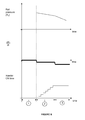
- Figure 6 combines a series of different figures together.
- the top figure shows how rail pressure varies over time (for before and during a test).
- the middle figure shows a corresponding plot of the rate of change of pressure over time.
- the bottom figure shows the activation time (injector ON times) for the injector under test.
- Figure 6 is also divided into three time periods.
- period 1 the rail pressure is being maintained, e.g. by the fuel pump, at a constant pressure.
- the derivative of the pressure with respect to time is equal to zero during this period.
- the injector ON time is set to zero during this period.
- Period 2 corresponds to the MDP test in accordance with embodiments of the present invention being run. It can be seen that drive pulses of increasing length are being applied. At the same time the fuel system has been set to a closed pressurised state and the pressure in the system is slowly decaying as a result natural leakage. The derivative (with respect to time) of the pressure shows a constant negative value.
- the injector ON time equals or exceeds the minimum drive pulse length for the injector under test and the pressure within the system falls at a faster rate. This can be seen by the change in gradient of the top figure which is also reflected in the change in the pressure derivative (which has moved to a second, more negative value compared to period 2).
- the injector ON time at the start of period 3 can therefore be used to set the minimum drive pulse for the injector under test.
Abstract
A method of determining a minimum drive pulse (MDP) for an injector (7) in a fuel system (1) within an engine, the injector being associated with a source of pressurised fuel (4), the method comprising: (a) sending a drive pulse of a first length to the injector; (b) determining an expected pressure in the fuel system at a given time; (c) measuring an actual pressure in the fuel system at the given time; (d) determining if an injection event has occurred by comparing the expected and actual values; (e) repeating steps (a) to (d) with drive pulses of progressively increasing lengths until an injection event has occurred and setting the drive pulse length associated with the injection event as the MDP of the injector.
Description
- The present invention relates to a method of determining injection parameters for an injector. In particular, the present invention relates to a method and associated apparatus for determining the minimum drive pulse of an injector within a fuel injection system of an engine. The present invention further relates to methods of diagnosing injector and injection system faults.
- There is a need in fuel injection equipment (FIE) to compensate for parts wearing over the lifetime of the product to ensure emissions and performance remains constant over life. One parameter that may vary over the lifetime of a fuel injector is the minimum drive pulse (MDP). A drive pulse relates to a drive signal applied to an injector via injector drive circuitry by an electronic control unit (ECU). The minimum drive pulse corresponds to the shortest drive signal that can be applied to an injector to initiate injection.
- One known method of Minimum Drive Pulse detection (MDP) in an FIE control system comprises monitoring a crank shaft speed within an engine system. In this method, the minimum duration of FIE injection time that induces a fuel quantity to be injected into the cylinder, is determined by monitoring crank shaft speed and detecting the moment at which sufficient fuel is injected such that a torque producing combustion event is produced. This method comprises disabling one cylinder out of a total of n number of cylinders and slowly increasing the injection time (i.e. slowly increasing the length of the drive pulse applied to the disabled cylinder/injector) on that disabled cylinder until the MDP is detected.
- Although this method can accurately determine injector MDP values it has the disadvantage that it is intrusive to normal engine operation because it involves injecting fuel into the engine system which results in a combustion event. This method is therefore noticeable in terms of torque and noise variations while the test is being carried out. Additionally this method is only able to measure MDP at a single reservoir pressure (i.e. when the engine is idling). If the reservoir pressure was, for example increased when the engine was idling then this would increase engine noise and make combustion less efficient (i.e. it would result in poor emissions performance).
- It is therefore an object of the present invention to provide a method of determining the minimum drive pulse of an injector in an injection system that substantially mitigates or overcomes the above mentioned problems.
- According to a first aspect of the present invention there is provided a method of determining a minimum drive pulse (MDP) for an injector in a fuel system within an engine, the injector being associated with a source of pressurised fuel, the method comprising: (a) sending a drive pulse of a first length to the injector; (b) determining an expected pressure in the fuel system at a given time; (c) measuring an actual pressure in the fuel system at the given time; (d) determining if an injection event has occurred by comparing the expected and actual pressure values; repeating steps (a) to (d) with drive pulses of progressively increasing lengths until an injection event has occurred and setting the drive pulse length associated with the injection event as the MDP of the injector.
- The present invention provides a method of determining the minimum drive pulse of an injector without the need to measure the crank shaft speed of the engine. The present invention measures the pressure within the fuel reservoir or common rail of an engine and analyses this pressure when an injector under test is sent drive pulse signals. The length of the drive pulse signals can be progressively increased until an injection event is detected and the minimum drive pulse can then be set accordingly. Conveniently, the present invention is arranged to compare the normal rate of pressure leakage in the system (the expected pressure) to actual measured pressure to determine when injection events have occurred. The determination of the expected pressure and the measurement of the actual pressure are scheduled for a given time (e.g. a predetermined period of time after the drive pulse is sent to the injector).
- It is noted in the following description that the terms "drive pulse", "drive pulse signal" and "injector ON time" are regarded as interchangeable and the length of a drive pulse has a direct relationship with the injector ON time.
- The advantage of the present invention is that it is unobtrusive and undetectable in the driveline since the test can be performed when the vehicle is in a "foot off pedal" or coasting condition. Additionally, the test drive pulses sent to the injector under test can be scheduled for periods of engine operation when injection of fuel into the engine cylinder associated with the test cylinder will not result in work output, e.g. during an exhaust stroke of an engine.
- Preferably, the method may be performed when the fuel system is in a closed pressurised state. Such a closed pressurised state may be achieved either by closing all the injectors within the fuel system and ceasing pumping of fuel to the source or by scheduling the test to run during a portion of the engine cycle when the injectors are closed and the pump is not actively charging the fuel source. In this latter example, the pump may conveniently be set to compensate for natural fuel leakage.
- Conveniently, the determining step may comprise determining if there is a significant change in pressure between the first and second pressure measurements to determine if an injection event has occurred.
- Preferably, the method may further comprise sampling the pressure in the fuel system at a plurality of measurement points in order to determine a pressure leakage profile for the injector such that the expected fuel pressure at the given time may be determined. In such an event, the determining step may comprise determining if the actual pressure measurement deviated from the determined pressure leakage profile. It is noted that the pressure leakage profile may comprise a pressure versus time relationship and the method may conveniently further comprise determining the presence of a fault in the fuel system if the determined pressure leakage profile exceeds a predefined profile envelope.
- The MDP value determined in step (e) may preferably be stored for use in engine operation. This MDP value may then be compared against a previously stored MDP value for the injector and the presence of an injector fault may be determined if the MDP value determined in step (e) deviates from the previously stored value by a predetermined amount. Additionally, or alternatively, the MDP value in step (e) may be compared against the MDP values of other injectors within the engine and the presence of an injector fault may be determined if the MDP value determined in step (e) deviates from the MDP values of the other injectors by a predetermined amount.
- Preferably, steps (a) to (d) are repeated according to step (e) by progressively increasing the length of the drive pulse by a fixed amount, Δa.
- Preferably, following the occurrence of an injection event, the method steps (a) to (e) are repeated for the same injector starting at the last drive pulse length not to cause an injection event and wherein the fixed amount by which the drive pulse is increased in step (e) is changed to a second fixed amount, Δb, wherein Δb < Δa. It is noted that varying the injector ON time interval in this way can be used to speed the MDP test up (i.e. by performing interval searching). For example, an initial test could be performed at a relatively course resolution to ascertain the rough MDP value and then a further test (or tests) could be run (starting at the last step prior to injection in the previous, "coarser" version of the test) with a finer resolution to determine a more accurate value for the MDP.
- Preferably, where the engine comprises a plurality of injectors, each injector may be tested in turn to determine the MDP of each injector.
- According to a second aspect of the present invention there is provided an electronic control unit arranged to determine a minimum drive pulse (MDP) for an injector in a fuel system within an engine, the injector being associated with a source of pressurised fuel, the electronic control unit being arranged to: a) send a drive pulse of a first length to the injector; (b) determine an expected pressure in the fuel system at a given time; (c) measure an actual pressure in the fuel system at the given time; (d) determine if an injection event has occurred by comparing the expected and actual pressure values; (e) repeat (a) to (d) with drive pulses of progressively increasing lengths until an injection event has occurred, the electronic control unit being arranged to set the drive pulse length associated with the injection event as the MDP of the injector.
- The invention extends to a carrier medium for carrying a computer readable code for controlling an electronic control unit to carry out the method of the first aspect of the invention.
- In order that the invention may be more readily understood, reference will now be made, by way of example, to the accompanying drawings in which:
-
Figure 1 shows a representation of a typical fuel system within an engine; -
Figure 2 shows a minimum drive pulse test method in accordance with an embodiment of the present invention; -
Figure 3 is a plot showing an example of pressure decay due to natural leakage versus pressure during an MDP test according to the present invention; -
Figure 4 shows a linear approximation of natural decay between injections; -
Figure 5 shows an MDP test in accordance with a further embodiment of the present invention; -
Figure 6 shows the relationship between rail pressure, the derivative of rail pressure with respect to time and the injection on time (TON) according to an embodiment of the present invention. -
Figure 1 shows a representation of afuel system 1 within an engine comprising afuel tank 2, a controllable highpressure fuel pump 3, a common rail (fuel reservoir) 4, arail pressure sensor 5, apressure limiter 6, a plurality ofinjectors 7 and an electronic control unit (ECU) 8. - In use the ECU 8 controls pumping of fuel from the
tank 2 to therail 4 by thepump 3. The ECU 8 also controls the operation of theinjectors 7 and receives sensor data on the pressure within therail 4 from thepressure sensor 5. -
Figure 2 is a flow chart showing a minimum drive pulse test in accordance with an embodiment of the present invention. InStep 10 the ECU (Electronic Control Unit 8) determines that the vehicle is operating in a foot-off condition. - In
Step 20 the ECU 8 initiates the MDP test and ceases all injections through theinjectors 7 within thefuel system 1. At the same time the ECU instructs afuel pump 3 to pressurise thefuel reservoir 4 to a predetermined pressure (PRES). - In
Step 30 the ECU 8 checks via thepressure sensor 5 whether the test pressure (PRES) has been achieved. - If the test pressure PRES has not been achieved then in
Step 40 the ECU waits for the pressure in thereservoir 4 to increase. After a predetermined pause the ECU 8 then returns toStep 30. - If the test pressure PRES has been achieved then the ECU 8 moves to
Step 50 in which the ECU 8 then instructs thepump 3 to cease pumping. After reducing the pump fuelling to zero output, the pressure in thefuel system 1 will begin to decay by natural leakage (to the low pressure fuel tank 2). It is noted however that, with the exception of natural fuel leakage, thefuel system 1 is now in a closed state since theinjectors 7 are not being operated and thefuel pump 3 is not supplying further fuel to thereservoir 4. The closed nature of thefuel system 1 at this point allows the following process steps to be used to determine injector MDP values. - It is noted that by reducing the fuel pump output to zero, the noise within the system is reduced which aids in the diagnosis process.
- The MDP test may be carried out at a variety of pressures and the ECU 8 may, for a given MDP test, select a particular pressure threshold (PTEST) from a number of pressure thresholds. In
Step 60, therefore, the ECU checks, via thepressure sensor 5, to see whether the pressure in the fuel system has dropped below the selected threshold value. If the pressure is not below the required threshold then the ECU waits (in Step 70) for the pressure to decay via the natural leakage process mentioned above. If the pressure in the fuel system is at the required level then the ECU moves to Step 80. - In
Step 80, the natural leakage characteristic of the fuel system is determined by taking two or more measurements of the reservoir pressure. From these measured pressure values a pressure leakage versus time function can be determined. In a preferred embodiment the leakage characteristic is approximated as a linear relationship to reduce processing requirements on the ECU. - In
Step 90, the ECU sends a drive pulse of duration TON to an injector. It is noted that in order to avoid the problems associated with the prior art the ECU sends the drive pulse at a point in the engine cycle that will not result in work output (e.g. during an exhaust stroke). - In
Step 100, the expected pressure (P1) within the reservoir is calculated from the leakage function determined inStep 80. - In
Step 110, the actual reservoir pressure is measured (P2). - In
Step 120 the ECU compares P1 and P2 to determine if there has been a significant change in pressure between the two readings, i.e. the ECU determines whether the difference between P1 and P2 is greater than a predetermined threshold value (for example, for a typical engine system this difference threshold could be of the order of 1 to 10 Bar. Depending on the engine system however a significant change in pressure could be outside of this range). - This may be determined by considering the rate of pressure change or by measuring a pressure difference of greater than a predetermined level.
- If the ECU determines that the pressure has not substantially deviated from the leakage function then in
Step 130 it increases the injector ON time (TON) by a predetermined increment and returns to Step 80. - In this way the ECU runs the MDP test with progressively increasing injector ON times until a significant change in pressure is detected in
Step 120. - Once a significant change in pressure has been determined then the length of the drive pulse that corresponds to the value of TON that resulted in that change is set, in
Step 140, as the minimum drive pulse for that injector. This value is stored by the ECU for use in engine operation. - The above process steps can then be repeated for each injector within the engine system.
- It is noted that an additional simple diagnostic test could be performed during
Step 80 of the above process, i.e. before drive pulses are sent to the injector to determine a minimum drive pulse. If, atStep 80 during the process of determining the pressure leakage profile, the ECU measures a pressure drop, the magnitude of which exceeds a stored value, then a component failure within the fuel system could be determined. This "component failure indicator pressure drop" value could be pre-loaded into the ECU during manufacture/installation or could be uploaded during servicing. - A further diagnostic test could be performed after
Step 140 in which the MDP value determined inStep 140 is compared to one or more previous MDP values for the injector under test. If the test result as determined inStep 140 has a drive pulse length that is significantly longer or shorter than the previous value then an injector failure may be determined. The permitted variation in MDP values between tests may be set as a parameter during ECU installation or during servicing etc. - A variation to the above further diagnostic test could be to compare the derived MDP value for the injector under test to the MDP values of the other injectors within the engine. If there is a significant difference between these values then an injector fault for the injector under test can be returned.
- If the increments by which the injector ON time is increased in
Step 130 are not small enough to provide adequate resolution then the test can be repeated starting at the step prior to MDP detection. In other words if the increment is 100µs and no injection was determined at an TON time of 600µs but injection was determined at 700µs then the test could be re-run with the initial TON time being set equal to 600µs and the increment set equal to 10µs. - It is also noted varying the injector ON time interval in this way can also be used to speed the MDP test up (i.e. by performing interval searching). For example, an initial test could be performed at a relatively course resolution to ascertain the rough MDP value and then a further test (or tests) could be run (starting at the last step prior to injection in the previous, "coarser" version of the test) with a finer resolution to determine a more accurate value for the MDP.
- It is also noted that the PTEST threshold in
Step 60 may be changed by the ECU so that an MDP versus pressure profile may be determined for each injector. This enables a far more accurate representation of the injector operation to be determined compared to the prior art in which measurements were only ever taken at a single reservoir pressure. -
Figure 3 shows a plot of pressure versus time for a fuel system operated in accordance with the above process.Trace 200 shows how pressure decays within a closed fuel system due to natural leakage.Trace 210 shows how the pressure varies during an MDP test in accordance with an embodiment of the present invention. It can be seen thatTrace 210 comprises a number of "steps" 220 corresponding to injection events within the engine. -
Figure 4 shows a representation ofFigure 3 in which the leakage function has been approximated as a linear relationship over time. Threesample pressure points Step 80 above) are shown. Aninjection event 280 is also shown and it can be seen that there is a noticeable pressure drop 290 from the extrapolated linear pressure leakage function. Such a pressure drop would be detected by the ECU (inStep 120 above) and would be indicative of an injection event occurring. - In certain circumstances it may be the case that the pressure sensor within the fuel system is not sufficiently sensitive to detect the pressure drop shown in
Figure 4 above. If this is the case then the method may be adapted slightly to perform a series ofinjections Step 90 ofFigure 2 ) on the same injector during one crankshaft revolution. This would therefore result in a largercumulative pressure drop 286 in the fuel system which may be detected by the pressure sensor. - This "multiple" injection variation is shown in
Figure 5 in which three injection events (280, 282, 284) are shown. Thepressure drop 286 due to these multiple injections is noticeably larger than thepressure drop 290 inFigure 4 and is now sufficiently large that thepressure sensor 5 can register the change. - It is noted that if the "multiple injection" variation of
Figure 5 embodiment is used then the activation pulse durations sent to the injector under test should be of a consistent duration. -
Figure 6 combines a series of different figures together. The top figure shows how rail pressure varies over time (for before and during a test). The middle figure shows a corresponding plot of the rate of change of pressure over time. Finally, the bottom figure shows the activation time (injector ON times) for the injector under test. -
Figure 6 is also divided into three time periods. Duringperiod 1 the rail pressure is being maintained, e.g. by the fuel pump, at a constant pressure. Correspondingly the derivative of the pressure with respect to time is equal to zero during this period. The injector ON time is set to zero during this period. -
Period 2 corresponds to the MDP test in accordance with embodiments of the present invention being run. It can be seen that drive pulses of increasing length are being applied. At the same time the fuel system has been set to a closed pressurised state and the pressure in the system is slowly decaying as a result natural leakage. The derivative (with respect to time) of the pressure shows a constant negative value. - At the start of
period 3 the injector ON time equals or exceeds the minimum drive pulse length for the injector under test and the pressure within the system falls at a faster rate. This can be seen by the change in gradient of the top figure which is also reflected in the change in the pressure derivative (which has moved to a second, more negative value compared to period 2). - The injector ON time at the start of
period 3 can therefore be used to set the minimum drive pulse for the injector under test. - It will be understood that the embodiments described above are given by way of example only and are not intended to limit the invention, the scope of which is defined in the appended claims. It will also be understood that the embodiments described may be used individually or in combination.
Claims (15)
- A method of determining a minimum drive pulse (MDP) for an injector (7) in a fuel system (1) within an engine, the injector being associated with a source of pressurised fuel (4), the method comprising:a) sending (90) a drive pulse of a first length to the injector;b) determining (100) an expected pressure in the fuel system at a given time;c) measuring (110) an actual pressure in the fuel system at the given time;d) determining (120) if an injection event has occurred by comparing the expected and actual pressure values;e) repeating steps (a) to (d) with drive pulses of progressively increasing lengths until an injection event has occurred and setting the drive pulse length associated with the injection event as the MDP of the injector.
- A method as claimed in Claim 1, wherein the method is performed when the fuel system is in a closed pressurised state.
- A method as claimed in Claim 2, wherein the closed pressurised state is achieved by closing all injectors within the fuel system and ceasing pumping of fuel to the source of pressurised fuel (4).
- A method as claimed in any preceding claim, wherein the determining step comprises determining if there is a significant change in pressure between the first and second pressure measurements to determine if an injection event has occurred.
- A method as claimed in any preceding claim, further comprising sampling (80) the pressure in the fuel system at a plurality of measurement points in order to determine a pressure leakage profile for the injector such that the expected fuel pressure at the given time may be determined..
- A method as claimed in Claim 5, wherein the determining step comprises determining if the actual pressure measurement deviated from the determined pressure leakage profile.
- A method as claimed in Claim 5 or Claim 6, wherein the pressure leakage profile comprises a pressure versus time relationship and the method further comprises determining the presence of a fault in the fuel system if the determined pressure leakage profile exceeds a predefined profile envelope.
- A method as claimed in any preceding claim, wherein the MDP value determined in step (e) is stored for use in engine operation.
- A method as claimed in Claim 8, wherein the MDP value in step (e) is compared against a previously stored MDP value for the injector and the presence of an injector fault is determined if the MDP value determined in step (e) deviates from the previously stored value by a predetermined amount.
- A method as claimed in Claim 8 or Claim 9, wherein the MDP value in step (e) is compared against the MDP values of other injectors within the engine and the presence of an injector fault is determined if the MDP value determined in step (e) deviates from the MDP values of the other injectors by a predetermined amount.
- A method as claimed in any preceding claim, wherein steps (a) to (d) are repeated according to step (e) by progressively increasing the length of the drive pulse by a fixed amount, Δa.
- A method as claimed in Claim 11, wherein, following the occurrence of an injection event, the method steps (a) to (e) are repeated for the same injector starting at the last drive pulse length not to cause an injection event and wherein the fixed amount by which the drive pulse is increased in step (e) is changed to a second fixed amount, Δb, wherein Δb < Δa.
- A method as claimed in any preceding claim, wherein the engine comprises a plurality of injectors and each injector is tested in turn to determine the MDP of each injector.
- An electronic control unit (8) arranged to determine a minimum drive pulse (MDP) for an injector (7) in a fuel system (1) within an engine, the injector being associated with a source of pressurised fuel (4), the electronic control unit being arranged to:a) send a drive pulse of a first length to the injector (7);b) determine an expected pressure in the fuel system (1) at a given time;c) measure an actual pressure in the fuel system at the given time;d) determine if an injection event has occurred by comparing the expected and actual pressure valuese) repeat (a) to (d) with drive pulses of progressively increasing lengths until an injection event has occurred, the electronic control unit being arranged to set the drive pulse length associated with the injection event as the MDP of the injector.
- A carrier medium for carrying a computer readable code for controlling an electronic control unit (8) to carry out the method of any one of Claims 1 to 13.
Priority Applications (2)
| Application Number | Priority Date | Filing Date | Title |
|---|---|---|---|
| EP10191380A EP2453124A1 (en) | 2010-11-16 | 2010-11-16 | Method of determining injection parameters for an injector |
| PCT/EP2011/070267 WO2012066044A1 (en) | 2010-11-16 | 2011-11-16 | Method of determining injection parameters for an injector |
Applications Claiming Priority (1)
| Application Number | Priority Date | Filing Date | Title |
|---|---|---|---|
| EP10191380A EP2453124A1 (en) | 2010-11-16 | 2010-11-16 | Method of determining injection parameters for an injector |
Publications (1)
| Publication Number | Publication Date |
|---|---|
| EP2453124A1 true EP2453124A1 (en) | 2012-05-16 |
Family
ID=43825272
Family Applications (1)
| Application Number | Title | Priority Date | Filing Date |
|---|---|---|---|
| EP10191380A Withdrawn EP2453124A1 (en) | 2010-11-16 | 2010-11-16 | Method of determining injection parameters for an injector |
Country Status (2)
| Country | Link |
|---|---|
| EP (1) | EP2453124A1 (en) |
| WO (1) | WO2012066044A1 (en) |
Cited By (7)
| Publication number | Priority date | Publication date | Assignee | Title |
|---|---|---|---|---|
| ITBO20120310A1 (en) * | 2012-06-06 | 2013-12-07 | Magneti Marelli Spa | METHOD TO DETERMINE THE LAW OF INJECTION OF A FUEL INJECTOR |
| ITBO20120309A1 (en) * | 2012-06-06 | 2013-12-07 | Magneti Marelli Spa | METHOD FOR DETERMINING THE LAW OF INJECTION OF A FUEL INJECTOR BY MEANS OF MOBILE MEDIA FOR VARIABLE REASON |
| EP2706216A1 (en) * | 2012-09-07 | 2014-03-12 | Delphi Technologies Holding S.à.r.l. | Method of determining fuel injector characteristics |
| KR20150079849A (en) * | 2012-11-28 | 2015-07-08 | 도요타지도샤가부시키가이샤 | Fuel injection apparatus and control method thereof |
| WO2017001180A1 (en) * | 2015-06-29 | 2017-01-05 | Continental Automotive Gmbh | Method and device for determining the minimum hydraulic injecting distance of a piezo servo injector |
| WO2023101700A1 (en) * | 2021-11-30 | 2023-06-08 | Cummins Inc. | High pressure fuel system controls, diagnostics, and prognostics using fuel mass change estimates |
| US11891962B1 (en) | 2022-08-25 | 2024-02-06 | Caterpillar Inc. | Gaseous fuel engine system operating strategy including hydrogen fueling amount based on performance target |
Citations (6)
| Publication number | Priority date | Publication date | Assignee | Title |
|---|---|---|---|---|
| EP0416265A1 (en) * | 1989-09-07 | 1991-03-13 | Robert Bosch Gmbh | Method and device for controlling fuel injection |
| EP1544446A2 (en) * | 2003-12-19 | 2005-06-22 | Denso Corporation | Fuel injection device |
| DE102006023468B3 (en) * | 2006-05-18 | 2007-09-13 | Siemens Ag | Fuel injection valve controlling method for use in e.g. gasoline engine, involves correcting controlling of selected fuel injection valve by correction factor, and using small amount of fuel to be detected for test injection |
| DE102006027823A1 (en) * | 2006-06-16 | 2007-12-20 | Siemens Ag | Method and device for adjusting the valve characteristic of a fuel injection valve |
| US20090164086A1 (en) * | 2007-12-20 | 2009-06-25 | Mert Geveci | System for determining critical on-times for fuel injectors |
| DE102008054409A1 (en) * | 2008-12-09 | 2010-06-10 | Robert Bosch Gmbh | Internal combustion engine controlling method for use in vehicle, involves determining minimum controlling duration based on response of rail pressure signal during stopping of internal combustion engine and when fuel injection is detected |
Family Cites Families (2)
| Publication number | Priority date | Publication date | Assignee | Title |
|---|---|---|---|---|
| DE19521791A1 (en) * | 1995-06-15 | 1996-12-19 | Daimler Benz Ag | Method for detecting malfunctions in a fuel injection system of an internal combustion engine |
| US7980120B2 (en) * | 2008-12-12 | 2011-07-19 | GM Global Technology Operations LLC | Fuel injector diagnostic system and method for direct injection engine |
-
2010
- 2010-11-16 EP EP10191380A patent/EP2453124A1/en not_active Withdrawn
-
2011
- 2011-11-16 WO PCT/EP2011/070267 patent/WO2012066044A1/en active Application Filing
Patent Citations (6)
| Publication number | Priority date | Publication date | Assignee | Title |
|---|---|---|---|---|
| EP0416265A1 (en) * | 1989-09-07 | 1991-03-13 | Robert Bosch Gmbh | Method and device for controlling fuel injection |
| EP1544446A2 (en) * | 2003-12-19 | 2005-06-22 | Denso Corporation | Fuel injection device |
| DE102006023468B3 (en) * | 2006-05-18 | 2007-09-13 | Siemens Ag | Fuel injection valve controlling method for use in e.g. gasoline engine, involves correcting controlling of selected fuel injection valve by correction factor, and using small amount of fuel to be detected for test injection |
| DE102006027823A1 (en) * | 2006-06-16 | 2007-12-20 | Siemens Ag | Method and device for adjusting the valve characteristic of a fuel injection valve |
| US20090164086A1 (en) * | 2007-12-20 | 2009-06-25 | Mert Geveci | System for determining critical on-times for fuel injectors |
| DE102008054409A1 (en) * | 2008-12-09 | 2010-06-10 | Robert Bosch Gmbh | Internal combustion engine controlling method for use in vehicle, involves determining minimum controlling duration based on response of rail pressure signal during stopping of internal combustion engine and when fuel injection is detected |
Cited By (12)
| Publication number | Priority date | Publication date | Assignee | Title |
|---|---|---|---|---|
| ITBO20120310A1 (en) * | 2012-06-06 | 2013-12-07 | Magneti Marelli Spa | METHOD TO DETERMINE THE LAW OF INJECTION OF A FUEL INJECTOR |
| ITBO20120309A1 (en) * | 2012-06-06 | 2013-12-07 | Magneti Marelli Spa | METHOD FOR DETERMINING THE LAW OF INJECTION OF A FUEL INJECTOR BY MEANS OF MOBILE MEDIA FOR VARIABLE REASON |
| EP2672096A1 (en) * | 2012-06-06 | 2013-12-11 | Magneti Marelli S.p.A. | Method for recalibrating the injection law of a fuel injector |
| US10385814B2 (en) | 2012-06-06 | 2019-08-20 | MAGNETI MARELLI S.p.A. | Method for refreshing the injection law of a fuel injector |
| EP2706216A1 (en) * | 2012-09-07 | 2014-03-12 | Delphi Technologies Holding S.à.r.l. | Method of determining fuel injector characteristics |
| KR20150079849A (en) * | 2012-11-28 | 2015-07-08 | 도요타지도샤가부시키가이샤 | Fuel injection apparatus and control method thereof |
| WO2017001180A1 (en) * | 2015-06-29 | 2017-01-05 | Continental Automotive Gmbh | Method and device for determining the minimum hydraulic injecting distance of a piezo servo injector |
| KR20180004808A (en) * | 2015-06-29 | 2018-01-12 | 콘티넨탈 오토모티브 게엠베하 | Method and apparatus for determining the minimum hydraulic injection distance of a piezoelectric servo injector |
| CN107787400A (en) * | 2015-06-29 | 2018-03-09 | 大陆汽车有限公司 | For the method and apparatus for the minimum hydraulic pressure injection interval for determining piezoelectric servo injector |
| US10233858B2 (en) | 2015-06-29 | 2019-03-19 | Continental Automotive Gmbh | Method and device for determining the minimum hydraulic injection interval of a piezo-servo injector |
| WO2023101700A1 (en) * | 2021-11-30 | 2023-06-08 | Cummins Inc. | High pressure fuel system controls, diagnostics, and prognostics using fuel mass change estimates |
| US11891962B1 (en) | 2022-08-25 | 2024-02-06 | Caterpillar Inc. | Gaseous fuel engine system operating strategy including hydrogen fueling amount based on performance target |
Also Published As
| Publication number | Publication date |
|---|---|
| WO2012066044A1 (en) | 2012-05-24 |
Similar Documents
| Publication | Publication Date | Title |
|---|---|---|
| EP2453124A1 (en) | Method of determining injection parameters for an injector | |
| EP2556231B1 (en) | Diagnosis device and method using an in-cylinder pressure sensor in an internal combustion engine | |
| US7905136B2 (en) | Method of operating a fuel injector | |
| US8955490B2 (en) | Fuel-pressure-sensor diagnosis device | |
| US8897996B2 (en) | Method for diagnosing a clogging of an injector in an internal combustion engine | |
| US9903331B2 (en) | Method for the injector-specific diagnosis of a fuel injection device and internal combustion engine having a fuel injection device | |
| JP2008223764A (en) | Vehicle diagnosis system and method | |
| ITTO960623A1 (en) | CALIBRATION PROCEDURE FOR AN INJECTION SYSTEM FITTED WITH INJECTORS. | |
| EP2706216A1 (en) | Method of determining fuel injector characteristics | |
| US10662890B2 (en) | Method for operating an internal combustion engine and electronic control unit for an internal combustion engine | |
| WO2019120802A1 (en) | Method of determining rail pressure in a common rail fuel system | |
| US7854160B2 (en) | Diagnostic systems and methods for the high pressure side of fuel systems in common fuel rail engines | |
| CN103168160A (en) | Method for monitoring the condition of a piezoinjector of a fuel injection system | |
| KR101842314B1 (en) | Method for determining a control volume of an injector | |
| CN102037227B (en) | Method for testing a pressure sensor of a fuel accumulator device | |
| EP0785349B1 (en) | Method and unit for diagnosing malfunctioning of the injectors of an internal combustion engine high-pressure injection system | |
| KR101942132B1 (en) | Method for learning a minimum actuation duration of injection valves of an internal combustion engine | |
| WO2008140404A1 (en) | Method and computer program product for identifying a malfunctioning cylinder of a multi-cylinder combustion engine | |
| EP1972769B1 (en) | Internal combustion engine fuel delivery system diagnosis device and method | |
| US8646322B2 (en) | Method and device for testing a fuel injector | |
| US9915216B2 (en) | Method for ascertaining the absolute injection quantity in an internal combustion engine and the system for this purpose | |
| WO2021252109A1 (en) | Systems and methods of fuel injection timing drift detection and compensation systems and methods of fuel injection timing drift detection and compensation | |
| GB2607532A (en) | Apparatuses, methods, systems, and techniques of misfire detection using engine speed sensor | |
| CN110195674B (en) | Injector drift monitoring for diagnostics | |
| KR20150005549A (en) | Method and device for operating an internal combustion engine |
Legal Events
| Date | Code | Title | Description |
|---|---|---|---|
| PUAI | Public reference made under article 153(3) epc to a published international application that has entered the european phase |
Free format text: ORIGINAL CODE: 0009012 |
|
| AK | Designated contracting states |
Kind code of ref document: A1 Designated state(s): AL AT BE BG CH CY CZ DE DK EE ES FI FR GB GR HR HU IE IS IT LI LT LU LV MC MK MT NL NO PL PT RO RS SE SI SK SM TR |
|
| AX | Request for extension of the european patent |
Extension state: BA ME |
|
| STAA | Information on the status of an ep patent application or granted ep patent |
Free format text: STATUS: THE APPLICATION IS DEEMED TO BE WITHDRAWN |
|
| 18D | Application deemed to be withdrawn |
Effective date: 20121117 |