EP0415101A1 - Exhaust system, in particular, device for the purification of exhaust gas - Google Patents
Exhaust system, in particular, device for the purification of exhaust gas Download PDFInfo
- Publication number
- EP0415101A1 EP0415101A1 EP90114642A EP90114642A EP0415101A1 EP 0415101 A1 EP0415101 A1 EP 0415101A1 EP 90114642 A EP90114642 A EP 90114642A EP 90114642 A EP90114642 A EP 90114642A EP 0415101 A1 EP0415101 A1 EP 0415101A1
- Authority
- EP
- European Patent Office
- Prior art keywords
- mat
- shielding
- exhaust gas
- rings
- shell
- Prior art date
- Legal status (The legal status is an assumption and is not a legal conclusion. Google has not performed a legal analysis and makes no representation as to the accuracy of the status listed.)
- Granted
Links
Images

Classifications
-
- F—MECHANICAL ENGINEERING; LIGHTING; HEATING; WEAPONS; BLASTING
- F01—MACHINES OR ENGINES IN GENERAL; ENGINE PLANTS IN GENERAL; STEAM ENGINES
- F01N—GAS-FLOW SILENCERS OR EXHAUST APPARATUS FOR MACHINES OR ENGINES IN GENERAL; GAS-FLOW SILENCERS OR EXHAUST APPARATUS FOR INTERNAL COMBUSTION ENGINES
- F01N13/00—Exhaust or silencing apparatus characterised by constructional features ; Exhaust or silencing apparatus, or parts thereof, having pertinent characteristics not provided for in, or of interest apart from, groups F01N1/00 - F01N5/00, F01N9/00, F01N11/00
- F01N13/08—Other arrangements or adaptations of exhaust conduits
- F01N13/10—Other arrangements or adaptations of exhaust conduits of exhaust manifolds
- F01N13/102—Other arrangements or adaptations of exhaust conduits of exhaust manifolds having thermal insulation
-
- F—MECHANICAL ENGINEERING; LIGHTING; HEATING; WEAPONS; BLASTING
- F01—MACHINES OR ENGINES IN GENERAL; ENGINE PLANTS IN GENERAL; STEAM ENGINES
- F01N—GAS-FLOW SILENCERS OR EXHAUST APPARATUS FOR MACHINES OR ENGINES IN GENERAL; GAS-FLOW SILENCERS OR EXHAUST APPARATUS FOR INTERNAL COMBUSTION ENGINES
- F01N13/00—Exhaust or silencing apparatus characterised by constructional features ; Exhaust or silencing apparatus, or parts thereof, having pertinent characteristics not provided for in, or of interest apart from, groups F01N1/00 - F01N5/00, F01N9/00, F01N11/00
- F01N13/009—Exhaust or silencing apparatus characterised by constructional features ; Exhaust or silencing apparatus, or parts thereof, having pertinent characteristics not provided for in, or of interest apart from, groups F01N1/00 - F01N5/00, F01N9/00, F01N11/00 having two or more separate purifying devices arranged in series
- F01N13/0097—Exhaust or silencing apparatus characterised by constructional features ; Exhaust or silencing apparatus, or parts thereof, having pertinent characteristics not provided for in, or of interest apart from, groups F01N1/00 - F01N5/00, F01N9/00, F01N11/00 having two or more separate purifying devices arranged in series the purifying devices are arranged in a single housing
-
- F—MECHANICAL ENGINEERING; LIGHTING; HEATING; WEAPONS; BLASTING
- F01—MACHINES OR ENGINES IN GENERAL; ENGINE PLANTS IN GENERAL; STEAM ENGINES
- F01N—GAS-FLOW SILENCERS OR EXHAUST APPARATUS FOR MACHINES OR ENGINES IN GENERAL; GAS-FLOW SILENCERS OR EXHAUST APPARATUS FOR INTERNAL COMBUSTION ENGINES
- F01N13/00—Exhaust or silencing apparatus characterised by constructional features ; Exhaust or silencing apparatus, or parts thereof, having pertinent characteristics not provided for in, or of interest apart from, groups F01N1/00 - F01N5/00, F01N9/00, F01N11/00
- F01N13/14—Exhaust or silencing apparatus characterised by constructional features ; Exhaust or silencing apparatus, or parts thereof, having pertinent characteristics not provided for in, or of interest apart from, groups F01N1/00 - F01N5/00, F01N9/00, F01N11/00 having thermal insulation
- F01N13/141—Double-walled exhaust pipes or housings
-
- F—MECHANICAL ENGINEERING; LIGHTING; HEATING; WEAPONS; BLASTING
- F01—MACHINES OR ENGINES IN GENERAL; ENGINE PLANTS IN GENERAL; STEAM ENGINES
- F01N—GAS-FLOW SILENCERS OR EXHAUST APPARATUS FOR MACHINES OR ENGINES IN GENERAL; GAS-FLOW SILENCERS OR EXHAUST APPARATUS FOR INTERNAL COMBUSTION ENGINES
- F01N3/00—Exhaust or silencing apparatus having means for purifying, rendering innocuous, or otherwise treating exhaust
- F01N3/08—Exhaust or silencing apparatus having means for purifying, rendering innocuous, or otherwise treating exhaust for rendering innocuous
- F01N3/10—Exhaust or silencing apparatus having means for purifying, rendering innocuous, or otherwise treating exhaust for rendering innocuous by thermal or catalytic conversion of noxious components of exhaust
- F01N3/24—Exhaust or silencing apparatus having means for purifying, rendering innocuous, or otherwise treating exhaust for rendering innocuous by thermal or catalytic conversion of noxious components of exhaust characterised by constructional aspects of converting apparatus
- F01N3/28—Construction of catalytic reactors
- F01N3/2839—Arrangements for mounting catalyst support in housing, e.g. with means for compensating thermal expansion or vibration
- F01N3/2853—Arrangements for mounting catalyst support in housing, e.g. with means for compensating thermal expansion or vibration using mats or gaskets between catalyst body and housing
- F01N3/2857—Arrangements for mounting catalyst support in housing, e.g. with means for compensating thermal expansion or vibration using mats or gaskets between catalyst body and housing the mats or gaskets being at least partially made of intumescent material, e.g. unexpanded vermiculite
-
- F—MECHANICAL ENGINEERING; LIGHTING; HEATING; WEAPONS; BLASTING
- F01—MACHINES OR ENGINES IN GENERAL; ENGINE PLANTS IN GENERAL; STEAM ENGINES
- F01N—GAS-FLOW SILENCERS OR EXHAUST APPARATUS FOR MACHINES OR ENGINES IN GENERAL; GAS-FLOW SILENCERS OR EXHAUST APPARATUS FOR INTERNAL COMBUSTION ENGINES
- F01N2310/00—Selection of sound absorbing or insulating material
- F01N2310/02—Mineral wool, e.g. glass wool, rock wool, asbestos or the like
-
- F—MECHANICAL ENGINEERING; LIGHTING; HEATING; WEAPONS; BLASTING
- F01—MACHINES OR ENGINES IN GENERAL; ENGINE PLANTS IN GENERAL; STEAM ENGINES
- F01N—GAS-FLOW SILENCERS OR EXHAUST APPARATUS FOR MACHINES OR ENGINES IN GENERAL; GAS-FLOW SILENCERS OR EXHAUST APPARATUS FOR INTERNAL COMBUSTION ENGINES
- F01N2350/00—Arrangements for fitting catalyst support or particle filter element in the housing
- F01N2350/02—Fitting ceramic monoliths in a metallic housing
-
- F—MECHANICAL ENGINEERING; LIGHTING; HEATING; WEAPONS; BLASTING
- F01—MACHINES OR ENGINES IN GENERAL; ENGINE PLANTS IN GENERAL; STEAM ENGINES
- F01N—GAS-FLOW SILENCERS OR EXHAUST APPARATUS FOR MACHINES OR ENGINES IN GENERAL; GAS-FLOW SILENCERS OR EXHAUST APPARATUS FOR INTERNAL COMBUSTION ENGINES
- F01N2470/00—Structure or shape of gas passages, pipes or tubes
- F01N2470/10—Tubes having non-circular cross section
Definitions
- the invention relates to an exhaust device with a double-shell housing, the inner shell being mounted at least in sections via an elastic bearing mat, in particular mineral fiber mat in the outer shell, in particular an exhaust gas cleaning device with an outer housing consisting of two half-shells, in which via an elastic bearing mat, in particular a so-called swelling mat, at least one honeycomb-structured carrier body and inner and outer shielding funnels and, if necessary, shielding rings are mounted between successive carrier bodies.
- the invention is therefore based on the object of designing an exhaust gas device of the type mentioned in such a way that the problems with axial and radial expansion differences are solved with a simple structure, and moreover with a favorable transition to any ceramic parts, without the occurrence of stress peaks and the risk of wrinkles can be.
- the shielding funnels and rings are formed from a close-meshed, sliding elastic wire mesh mat and are held fixed on both ends.
- the configuration according to the invention can solve a number of special problems in one.
- a wire mesh mat - mesh fabrics with a mesh width of ⁇ 0.5 mm are particularly suitable - can be processed very easily in press or deep-drawing molds, so that even very complicated shell structures can be produced.
- shielding parts made of a wire mesh mat, both in the longitudinal direction and radially and in the transverse direction are very large Provide elasticity so that the expansion differences mentioned at the beginning can be easily absorbed in the wire mesh in both the axial direction and in the radial direction.
- the special properties of a wire mesh mat also evidently prevent any risk of creasing at different expansions, for example of the shielding funnel produced from such a wire mesh mat and of the ceramic support body which is subsequently clamped around.
- the porosity of a shielding funnel made of a wire mesh mat does not interfere in any way with the dense design of a shielding funnel drawn from sheet metal, since with a sufficiently small mesh size, sufficient elasticity of the inner shielding component produced therefrom is still guaranteed on the one hand and on the other hand due to the occurring mesh opening neither damage to the mineral fiber mat can take place, which in practice is anyway more heat-resistant than metal, but on the other hand also blowing out or otherwise falling out of parts from the mineral fiber mat can be reliably prevented.
- the shielding funnel 7 which consists of a wire mesh mat, is resiliently stretched onto the end of the carrier body 4, an additional holding effect also being provided by the pressure of the surrounding mineral fiber mat 5.
- the inner shielding cylinder can not only be placed very easily around complicated inner structures, as must be the case with the complex-shaped carrier body 4 (FIG. 2), but there can be neither thermally induced stress peaks nor warping or wrinkling Shielding funnels or shielding rings, neither in the radial nor in the axial direction.
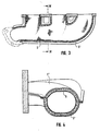
- 3 and 4 is shown using an insulated double shell manifold with a metallic outer housing 1 'and an inner housing 9, as the inventive design of the inner housing from a wire mesh mat in a very simple and effective form can also be used in other types of exhaust devices, to avoid the otherwise usual complicated sliding seats in the area of the inner housing and / or outer housing.
- a mineral fiber mat 5 'between the outer housing 1' and the wire mesh mat-shaped inner housing 9 provided, because of the complicated structure, the mineral fiber mat 5 'is preferably composed of divided blanks, which preferably abut against one another with their abutting edges.
- the invention is not restricted to the exemplary embodiments shown.
- This design can namely be provided in the area of the shielding funnels or rings that the elastic bearing mat is completely eliminated over large sections, which in turn has the advantage that no high compressive forces of this elastic fiber mat have to be absorbed by the wire mesh shielding funnels and shielding rings .
- the production from the wire mesh mat instead of the usual metal sheets has the advantage that, for example, damage to the monolith is eliminated by the encompassing edge of the shielding funnel or shielding ring. Due to the thermally insulating intermediate layer, excessive thermal heating of the outer shell is avoided even without pulling the bearing mat over the area of the rings and shielding funnels, and on the other hand - in particular if the thermally insulating intermediate layer as paper, film or the like. is made of thermally resistant material - prevents hot exhaust gases from getting into the space between the inner shell and the outer shell, so that they are neither there heating or blowing out the elastic mineral fiber mat present in the area of the monolith at the latest.
Abstract
Description
Die Erfindung bezieht sich auf eine Abgasvorrichtung mit einem zweischaligen Gehäuse, wobei die Innenschale zumindest abschnittsweise über eine elastische Lagermatte, insb. Mineralfasermatte in der Außenschale gelagert ist, insbesondere eine Abgasreinigungsvorrichtung mit einem aus zwei Halbschalen bestehenden Außengehäuse, in welchem über eine elastische Lagermatte, insbes. eine sogenannte Quellmatte, wenigstens ein wabenförmig strukturierter Trägerkörper sowie ein- und ausgangsseitige innere Abschirmtrichter sowie ggfs. Abschirmringe zwischen aufeinanderfolgenden Trägerkörpern gelagert sind.The invention relates to an exhaust device with a double-shell housing, the inner shell being mounted at least in sections via an elastic bearing mat, in particular mineral fiber mat in the outer shell, in particular an exhaust gas cleaning device with an outer housing consisting of two half-shells, in which via an elastic bearing mat, in particular a so-called swelling mat, at least one honeycomb-structured carrier body and inner and outer shielding funnels and, if necessary, shielding rings are mounted between successive carrier bodies.
Bei derartigen Abgasvorrichtungen mit zweischaligem Gehäuse besteht grundsätzlich das Problem eines Ausgleichs der thermischen Ausdehnungsunterschiede zwischen der inneren Schale und der äußeren Schale, die wegen der thermischen Abschirmung durch die Mineralfasermatte im Betrieb beträchtliche Temperaturunterschiede aufweist. Üblicherweise geht man zum Abfangen der thermischen Ausdehnungsunterschiede davon aus, daß man zu wenigstens auf irgend einer Seite einen Schiebesitz einbaut. Dabei ergibt sich die mißliche Situation, daß man zwei unterschiedliche thermische Ausdehnungsunterschiede berücksichtigen muß, und zwar einmal radiale Dehnungsunterschiede zwischen Innenschale und Außenschale und zum anderen axiale Dehnungsunterschiede zwischen dem inneren Auskleidungstrichter und beispielsweise dem daran anstoßenden meist keramischen Trägerkörper. Selbst wenn man durch eine Segmentaufteilung auch diese radialen Dehnungsunterschiede aufzufangen versucht, so hat es sich in der Praxis gezeigt, daß die überlappenden Bereiche, in denen die Dehnungsverschiebung stattfinden sollte, bei den hohen Betriebstemperaturen häufig so stark aneinander haften, daß in Wirklichkeit ein funktionierender Schiebesitz gar nicht zustande kommt und somit Auskleidungstrichter und sonstige Abstandsringe richtiggehende Falten werfen, was zu erheblichen Spannungen und einer großen Bruchgefahr der Keramikmonolithe führt. Aber auch bei Abgasvorrichtungen ohne eingebaute mineralische Trägerkörper, wie beispielsweise bei isolierten Doppelschalenkrümmern, ist das Problem des Abfangens der Dehnungsunterschiede der gasführenden inneren Krümmerschalen gegenüber den tragenden äußeren Krümmerschalen in gleicher Weise relvant.In such exhaust gas devices with a two-shell housing, there is basically the problem of compensating for the thermal expansion differences between the inner shell and the outer shell, which has considerable temperature differences during operation because of the thermal shielding by the mineral fiber mat. To compensate for the thermal expansion differences, it is usually assumed that a sliding seat is installed on at least one side. This results in the unfortunate situation that two different thermal expansion differences have to be taken into account, namely radial expansion differences between the inner shell and the outer shell and secondly axial expansion differences between the inner lining funnel and, for example, the mostly ceramic carrier body which is in contact with it. Even if one tries to compensate for these radial expansion differences by dividing the segments, it has been shown in practice that the overlapping areas in which the expansion shift should take place often so strongly at the high operating temperatures are liable for the fact that a functioning sliding seat does not come into being at all and thus lining funnels and other spacer rings throw correct folds, which leads to considerable tension and a great risk of breakage of the ceramic monoliths. But even in exhaust gas devices without built-in mineral carrier bodies, such as, for example, in insulated double-shell manifolds, the problem of absorbing the expansion differences of the gas-carrying inner manifold shells compared to the load-bearing outer manifold shells is relevant in the same way.
Der Erfindung liegt daher die Aufgabe zugrunde, eine Abgasvorrichtung der eingangs genannten Art so auszugestalten, daß mit einfachem Aufbau die Probleme mit axialen und radialen Dehnungsunterschieden, noch dazu bei günstigem Übergang zu etwaigen keramischen Teilen, ohne das Auftreten von Spannungsspitzen und die Gefahr eines Faltenbildens gelöst werden können.The invention is therefore based on the object of designing an exhaust gas device of the type mentioned in such a way that the problems with axial and radial expansion differences are solved with a simple structure, and moreover with a favorable transition to any ceramic parts, without the occurrence of stress peaks and the risk of wrinkles can be.
Zur Lösung dieser Aufgabe ist erfindungsgemäß vorgesehen, daß die Abschirmtrichter und -ringe aus einer engmaschigen schiebeelastischen Drahtgewebematte gebildet und beidends fixiert gehaltert sind.To solve this problem it is provided according to the invention that the shielding funnels and rings are formed from a close-meshed, sliding elastic wire mesh mat and are held fixed on both ends.
Durch die erfindungsgemäße Ausgestaltung lassen sich in einem gleich eine Reihe von besonderen Problemen lösen. Zum einen läßt sich eine solche Drahtgewebematte - geeignet sind dabei bevorzugt Maschengewebe mit einer Maschenweite < 0,5 mm - sehr einfach in Preß- oder Tiefziehformen verarbeiten, so daß auch sehr komplizierte Schalengebilde gefertigt werden können. Zum anderen sind derartige Abschirmteile aus einer Drahtgewebematte, sowohl in Längsrichtung als auch radial und in Querrichtung, mit einer sehr großen Elastizität versehen, so daß die eingangs angesprochenen Dehnungsunterschiede sowohl in axialer Richtung als auch in radialer Richtung bequem im Drahtgewebe abgefangen werden können.The configuration according to the invention can solve a number of special problems in one. On the one hand, such a wire mesh mat - mesh fabrics with a mesh width of <0.5 mm are particularly suitable - can be processed very easily in press or deep-drawing molds, so that even very complicated shell structures can be produced. On the other hand, such shielding parts made of a wire mesh mat, both in the longitudinal direction and radially and in the transverse direction, are very large Provide elasticity so that the expansion differences mentioned at the beginning can be easily absorbed in the wire mesh in both the axial direction and in the radial direction.
Bei einer bevorzugten Ausbildung einer erfindungsgemäßen Abgasreinigungsvorrichtung derart, daß der im Anschlußstutzen verklemmte oder verschweißte Abschirmtrichter das stirnseitige Ende des Trägerkörpers klemmend umgreift, wobei etwaige Abschirmringe in entsprechender Weise die benachbarten Trägerkörperenden klemmend umgreifen sollen, ergibt sich mit dem Ausgleich der Dehnungstoleranz auch eine absolute Sicherheit dagegen, daß durch etwaige unterschiedliche Dehnungen allzu starke Spannungsspitzen auftreten, die zu einer Zerstörung der dünnwandigen Keramik führen könnten.In a preferred embodiment of an exhaust gas purification device according to the invention in such a way that the shielding funnel, which is clamped or welded in the connecting piece, clamps around the front end of the carrier body, with any shielding rings correspondingly encompassing the adjacent ends of the carrier body, there is also absolute security against this with the compensation of the expansion tolerance that due to possible different strains, too strong stress peaks occur, which could lead to the destruction of the thin-walled ceramic.
Die besondere Eigenschaften einer Drahtgewebematte verhindern ersichtlich auch jegliche Gefahr eines Faltenwerfens bei unterschiedlichen Dehnungen beispielsweise des aus einer solchen Drahtgewebematte hergestellten Abschirmtrichtrs und des anschließend klemmend umgriffenen keramischen Trägerkörpers. Wie dabei umfangreiche Versuche gezeigt haben, stört die Porosität eines Abschirmtrichters aus einer Drahtgewebematte gegenüber der dichten Ausbildung eines aus Blech tiefgezogenen Abschirmtrichters in keiner Weise, da bei genügend kleiner Maschengröße einerseits immer noch eine ausreichende Elastizität des daraus hergestellten inneren Abschirmbauteils gewährleistet ist und andererseits durch die auftretende Maschenöffnung weder eine Beschädigung der Mineralfasermatte stattfinden kann, die ja in der Praxis sowieso hitzebeständiger ist als Metall, andererseits aber auch ein Ausblasen oder sonstiges Herausfallen von Teilen aus der Mineralfasermatte zuverlässig verhindert werden kann.The special properties of a wire mesh mat also evidently prevent any risk of creasing at different expansions, for example of the shielding funnel produced from such a wire mesh mat and of the ceramic support body which is subsequently clamped around. As extensive tests have shown, the porosity of a shielding funnel made of a wire mesh mat does not interfere in any way with the dense design of a shielding funnel drawn from sheet metal, since with a sufficiently small mesh size, sufficient elasticity of the inner shielding component produced therefrom is still guaranteed on the one hand and on the other hand due to the occurring mesh opening neither damage to the mineral fiber mat can take place, which in practice is anyway more heat-resistant than metal, but on the other hand also blowing out or otherwise falling out of parts from the mineral fiber mat can be reliably prevented.
Weitere Vorteile, Merkmale und Einzelheiten der Erfindung ergeben sich aus der nachfolgenden Beschreibung eines Ausführungsbeispiels sowie anhand der Zeichnung. Dabei zeigen:
- Fig. 1 einen Längsschnitt durch eine erfindungsgemäß ausgebildete Abgasreinigungsvorrichtung,
- Fig. 2 einen Schnitt längs der Linie II - II in Fig. 1,
- Fig. 3 einen Längsschnitt durch einen isolierten Doppelschalenkrümmer mit aus einer Drahtgewebematte gebildetem Innengehäuse und
- Fig. 4 einen Querschnitt längs der Linie IV - IV in Fig. 3.
- 1 shows a longitudinal section through an exhaust gas cleaning device designed according to the invention,
- 2 shows a section along the line II-II in FIG. 1,
- Fig. 3 shows a longitudinal section through an insulated double shell manifold with an inner housing formed from a wire mesh mat and
- 4 shows a cross section along the line IV-IV in FIG. 3.
Die in den Fig. 1 und 2 dargestellte Abgasreinigungsvorrichtung umfaßt in an sich bekannter Weise ein zweischaliges Außengehäuse 1, dessen beide Halbschalen 1a und 1b an ihrem in der Trennebene verlaufenden Flanschen 2 und 3 miteinander verschweißt sind. Im Außengehäuse 1 sind im gezeigten Ausführungsbeispiel zwei wabenförmig strukturierte keramische Trägerkörper 4 u. 4′ mit Hilfe einer über die gesamte Länge der Abgasreinigungsvorrichtung durchgehenden Mineralfasermatte 5 gelagert, die in der Mitte voneinander beabstandet sind. Der den Eingangskonus 6 und den nicht gezeigten Ausgangskonus überdeckende an sich bekannte innere Abschirmtrichter 7 besteht erfindungsgemäß aus einer Drahtgewebematte, die sowohl auf der Eingangsseite im Anschlußstutzen befestigt ist - was im vorliegenden Fall durch eine Verklemmung erreicht ist - als auch auf der gegenüberliegenden Seite fixiert gehaltert ist. Zu diesem Zweck ist im gezeigten Ausführungsbeispiel der aus einer Drahtgewebematte bestehende Abschirmtrichter 7 federnd elastisch auf das Ende des Trägerkörpers 4 aufgespannt, wobei eine zusätzliche Halterungswirkung auch durch den Preßdruck der umgebenden Mineralfasermatte 5 vorhanden ist. In gleicher Weise ist auch der Abschirmring 10 für den Spalt 11 zwischen den benachbarten Trägerkörpern 4 u. 4′ aus einer Drahtgewebematte hergestellt und auf die Trägerkörperenden aufgespannt. Durch diese Ausbildung läßt sich der innere Abschirmzylinder nicht nur sehr einfach auch um komplizierte Innenstrukturen herumlegen, wie es bei dem komplex geformten Trägerkörper 4 (Fig. 2) der Fall sein muß, sondern es können weder thermisch bedingte Spannungsspitzen auftreten noch ein Verwerfen oder Faltenwerfen der Abschirmtrichter bzw. Abschirmringe, weder in radialer noch in axialer Richtung. Dabei versteht es sich von selbst, daß vor dem Aufbringen der Außenschalen 1a u. 1b der um den Trägerkörper 4 gelegte Abschirmtrichter 7 sich in die obere Mulde 8 zunächst nicht völlig hineinlegt, jedenfalls dann nicht, wenn er mit Vorspannung auf den Trägerkörper 4 aufgespannt wird. Mit dem Zusammendrücken der beiden Schalenhälften 1a u. 1b des Außengehäuses wird aber ein etwaiges Abheben an dieser Stelle wieder korrigiert.1 and 2 comprises, in a manner known per se, a two-shell
In den Fig. 3 und 4 ist anhand eines isolierten Doppelschalenkrümmers mit einem metallischen Außengehäuse 1′ und einem Innengehäuse 9 dargestellt, wie die erfindungsgemäße Ausbildung des Innengehäuses aus einer Drahtgewebematte in sehr einfacher und wirksamer Form auch bei anderen Arten von Abgasvorrichtungen dazu verwendet werden kann, die sonst bislang üblichen komplizierten Schiebesitze im Bereich des Innengehäuses und/oder Außengehäuses zu vermeiden. Auch dort ist, wie üblich, eine Minerealfasermatte 5′ zwischen dem Außengehäuse 1′ und dem aus der Drahtgewebe matte geformten Innengehäuse 9 vorgesehen, wobei wegen der komplizierten Struktur die Mineralfasermatte 5′ bevorzugt aus geteilten Zuschnitten zusammengesetzt ist, die mit ihren Stoßkanten vorzugsweise dichtend aneinander stoßen.3 and 4 is shown using an insulated double shell manifold with a metallic outer housing 1 'and an
Die Erfindung ist nicht auf die dargestellten Ausführungsbeispiele beschränkt. So wäre es insbesondere auch möglich, die Abschirmtrichter und -ringe aus zwei durch eine thermisch isolierende Zwischenschicht getrennten Lagen von Drahtgewebematten zu bilden, was bevorzugt in der Weise geschehen kann, daß die Zwischenschicht aus Keramikfasermaterial in Form eines Gewebes, Papiers, Blankets oder Vlieses besteht.The invention is not restricted to the exemplary embodiments shown. In particular, it would also be possible to form the shielding funnels and rings from two layers of wire mesh mats separated by a thermally insulating intermediate layer, which can preferably be done in such a way that the intermediate layer consists of ceramic fiber material in the form of a fabric, paper, blankets or fleece .
Durch diese Ausbildung kann nämlich im Bereich der Abschirmtrichter oder -ringe auch vorgesehen sein, daß die elastische Lagermatte über weite Abschnitte völlig entfällt, was wiederum den Vorteil hat, daß auch keine hohen Druckkräfte dieser elastischen Fasermatte von den Drahtgewebe-Abschirmtrichtern und Abschirmringen aufgefangen werden müssen. Die Fertigung aus der Drahtgewebematte anstelle der üblichen Metallbleche hat den Vorteil, daß beispielsweise eine Beschädigung des Monolithen durch den umgreifenden Rand des Abschirmtrichters oder Abschirmrings ausgeschaltet ist. Durch die thermisch isolierende Zwischenschicht wird aber auch ohne das Durchziehen der Lagermatte auch über den Bereich der Ringe und Abschirmtrichter eine zu starke thermische Aufheizung der Außenschale vermieden und auf der anderen Seite - insbesondere wenn die thermisch isolierende Zwischenschicht als Papier, Folie 0d.dgl. aus thermisch widerstandsfähigem Material gebildet ist - verhindert, daß heiße Abgase in den Zwischenraum zwischen der Innenschale und der Außenschale gelangen können, so daß sie dort weder eine Aufheizung, noch ein Ausblasen der spätestens im Bereich des Monolithen vorhandenen elastischen Mineralfasermatte bewirken können.This design can namely be provided in the area of the shielding funnels or rings that the elastic bearing mat is completely eliminated over large sections, which in turn has the advantage that no high compressive forces of this elastic fiber mat have to be absorbed by the wire mesh shielding funnels and shielding rings . The production from the wire mesh mat instead of the usual metal sheets has the advantage that, for example, damage to the monolith is eliminated by the encompassing edge of the shielding funnel or shielding ring. Due to the thermally insulating intermediate layer, excessive thermal heating of the outer shell is avoided even without pulling the bearing mat over the area of the rings and shielding funnels, and on the other hand - in particular if the thermally insulating intermediate layer as paper, film or the like. is made of thermally resistant material - prevents hot exhaust gases from getting into the space between the inner shell and the outer shell, so that they are neither there heating or blowing out the elastic mineral fiber mat present in the area of the monolith at the latest.
In diesem Zusammenhang sei schließlich noch darauf hingewiesen, daß infolge der meist gegebenen Unsymmetrie von Drahtgewebematten hinsichtlich ihrer Schiebeelastizität in unterschiedlichen Richtungen man selbstverständlich die Orientierung der Matten beim Einbau als Abschirmtrichter oder Abschirmring so wählen wird, daß in der zu erwartenden größten Dehnungsrichtung auch die größte Schiebeelastizität besteht.In this context, it should finally be pointed out that due to the mostly existing asymmetry of wire mesh mats with regard to their sliding elasticity in different directions, the orientation of the mats when installing as a shielding funnel or shielding ring will of course be chosen such that the greatest sliding elasticity is also expected in the greatest direction of expansion to be expected consists.
Claims (5)
Applications Claiming Priority (2)
| Application Number | Priority Date | Filing Date | Title |
|---|---|---|---|
| DE3929205A DE3929205A1 (en) | 1989-09-02 | 1989-09-02 | EXHAUST APPARATUS, IN PARTICULAR. EXHAUST GAS PURIFICATION DEVICE |
| DE3929205 | 1989-09-02 |
Publications (2)
| Publication Number | Publication Date |
|---|---|
| EP0415101A1 true EP0415101A1 (en) | 1991-03-06 |
| EP0415101B1 EP0415101B1 (en) | 1993-09-22 |
Family
ID=6388521
Family Applications (1)
| Application Number | Title | Priority Date | Filing Date |
|---|---|---|---|
| EP90114642A Expired - Lifetime EP0415101B1 (en) | 1989-09-02 | 1990-07-31 | Exhaust system, in particular, device for the purification of exhaust gas |
Country Status (3)
| Country | Link |
|---|---|
| EP (1) | EP0415101B1 (en) |
| DE (2) | DE3929205A1 (en) |
| ES (1) | ES2044341T3 (en) |
Cited By (8)
| Publication number | Priority date | Publication date | Assignee | Title |
|---|---|---|---|---|
| EP0472009A1 (en) * | 1990-08-22 | 1992-02-26 | Firma J. Eberspächer | Exhaust gas purifying device with two exhaust gas treatment bodies one behind the other |
| EP0603754A1 (en) * | 1992-12-22 | 1994-06-29 | LEISTRITZ AG & CO. Abgastechnik | Device for reducing exhaust emissions, especially for motor vehicles |
| EP0719912A1 (en) * | 1994-12-30 | 1996-07-03 | Firma J. Eberspächer | Exhaust gas treatment device of internal combustion engines |
| FR2751376A1 (en) * | 1996-07-17 | 1998-01-23 | Daimler Benz Ag | ELBOW EXHAUST TUBING FOR GUIDING THE EXHAUST GASES OF AN INTERNAL COMBUSTION ENGINE |
| EP1308607A2 (en) * | 2001-11-02 | 2003-05-07 | Delphi Technologies, Inc. | End cones for exhaust emission control devices and methods of making |
| FR3084109A1 (en) * | 2018-07-23 | 2020-01-24 | Renault S.A.S. | THERMAL INSULATION DEVICE ON THE EXHAUST OF A HEAT ENGINE |
| DE102019104940A1 (en) * | 2019-02-27 | 2020-08-27 | Eberspächer Exhaust Technology GmbH & Co. KG | Exhaust converter housing structure |
| CN115585037A (en) * | 2022-09-27 | 2023-01-10 | 九江学院 | Tail gas trapping structure |
Families Citing this family (5)
| Publication number | Priority date | Publication date | Assignee | Title |
|---|---|---|---|---|
| DE4201426C2 (en) * | 1992-01-21 | 1994-03-31 | Leistritz Abgastech | Emission control device |
| DE4323791C2 (en) * | 1993-07-15 | 1997-03-20 | Daimler Benz Ag | Exhaust aftertreatment device for the catalytic purification of the exhaust gases from internal combustion engines |
| DE10018805A1 (en) | 2000-04-15 | 2001-11-29 | Volkswagen Ag | Method and device for producing a catalyst with a monolith having a polygonal cross section |
| DE102009037520A1 (en) * | 2009-08-17 | 2011-04-21 | Poroson Gmbh | Exhaust manifold for mounting at cylinder head of internal-combustion engine, has gas channel including metal fabric provided with chaining threads, weft threads and pores that are formed between chaining threads and weft threads |
| US9790836B2 (en) | 2012-11-20 | 2017-10-17 | Tenneco Automotive Operating Company, Inc. | Loose-fill insulation exhaust gas treatment device and methods of manufacturing |
Citations (3)
| Publication number | Priority date | Publication date | Assignee | Title |
|---|---|---|---|---|
| EP0193072A1 (en) * | 1985-02-22 | 1986-09-03 | Leistritz Aktiengesellschaft | Catalytic-emission control device |
| EP0275565A1 (en) * | 1987-01-02 | 1988-07-27 | Firma J. Eberspächer | Catalytic purification device for vehicle exhaust gases |
| DE3821397A1 (en) * | 1988-06-24 | 1989-12-28 | Eberspaecher J | Device for the catalytic cleaning of internal combustion engine exhaust gases |
Family Cites Families (5)
| Publication number | Priority date | Publication date | Assignee | Title |
|---|---|---|---|---|
| DE2222663C3 (en) * | 1972-05-09 | 1975-03-06 | Zeuna-Staerker Kg, 8900 Augsburg | Process for the production of a device for cleaning the exhaust gases of internal combustion engines |
| JPS54160558A (en) * | 1978-05-19 | 1979-12-19 | Chuo Hatsujo Kk | Forming metal wire cushion body and product thereof |
| DE3509790A1 (en) * | 1985-03-19 | 1986-10-09 | LEISTRITZ Maschinenfabrik GmbH, 8500 Nürnberg | Exhaust emission control device for motor vehicles |
| DE3710299A1 (en) * | 1987-03-28 | 1988-10-13 | Eberspaecher J | ARRANGEMENT FOR HOLDING A CATALYST IN A HOUSING IN THE EXHAUST SYSTEM OF A ENGINE USED WITH LIQUID FUEL |
| DE3729994A1 (en) * | 1987-09-08 | 1989-03-16 | Bischoff Erhardt Gmbh Co Kg | Apparatus for the catalytic purification of exhaust gases |
-
1989
- 1989-09-02 DE DE3929205A patent/DE3929205A1/en active Granted
-
1990
- 1990-07-31 ES ES90114642T patent/ES2044341T3/en not_active Expired - Lifetime
- 1990-07-31 EP EP90114642A patent/EP0415101B1/en not_active Expired - Lifetime
- 1990-07-31 DE DE90114642T patent/DE59002823D1/en not_active Expired - Fee Related
Patent Citations (3)
| Publication number | Priority date | Publication date | Assignee | Title |
|---|---|---|---|---|
| EP0193072A1 (en) * | 1985-02-22 | 1986-09-03 | Leistritz Aktiengesellschaft | Catalytic-emission control device |
| EP0275565A1 (en) * | 1987-01-02 | 1988-07-27 | Firma J. Eberspächer | Catalytic purification device for vehicle exhaust gases |
| DE3821397A1 (en) * | 1988-06-24 | 1989-12-28 | Eberspaecher J | Device for the catalytic cleaning of internal combustion engine exhaust gases |
Non-Patent Citations (1)
| Title |
|---|
| PATENT ABSTRACTS OF JAPAN vol. 12, no. 195 (M-705)(3042) 07 Juni 1988, & JP-A-63 001708 (YUTAKA) 06 Januar 1988, * |
Cited By (11)
| Publication number | Priority date | Publication date | Assignee | Title |
|---|---|---|---|---|
| EP0472009A1 (en) * | 1990-08-22 | 1992-02-26 | Firma J. Eberspächer | Exhaust gas purifying device with two exhaust gas treatment bodies one behind the other |
| EP0603754A1 (en) * | 1992-12-22 | 1994-06-29 | LEISTRITZ AG & CO. Abgastechnik | Device for reducing exhaust emissions, especially for motor vehicles |
| EP0719912A1 (en) * | 1994-12-30 | 1996-07-03 | Firma J. Eberspächer | Exhaust gas treatment device of internal combustion engines |
| FR2751376A1 (en) * | 1996-07-17 | 1998-01-23 | Daimler Benz Ag | ELBOW EXHAUST TUBING FOR GUIDING THE EXHAUST GASES OF AN INTERNAL COMBUSTION ENGINE |
| EP1308607A2 (en) * | 2001-11-02 | 2003-05-07 | Delphi Technologies, Inc. | End cones for exhaust emission control devices and methods of making |
| EP1308607A3 (en) * | 2001-11-02 | 2004-06-09 | Delphi Technologies, Inc. | End cones for exhaust emission control devices and methods of making |
| FR3084109A1 (en) * | 2018-07-23 | 2020-01-24 | Renault S.A.S. | THERMAL INSULATION DEVICE ON THE EXHAUST OF A HEAT ENGINE |
| WO2020020828A1 (en) * | 2018-07-23 | 2020-01-30 | Renault S.A.S | Thermal insulation device for the exhaust of a heat engine |
| CN112469892A (en) * | 2018-07-23 | 2021-03-09 | 雷诺股份公司 | Thermal insulation device for exhaust gases of a heat engine |
| DE102019104940A1 (en) * | 2019-02-27 | 2020-08-27 | Eberspächer Exhaust Technology GmbH & Co. KG | Exhaust converter housing structure |
| CN115585037A (en) * | 2022-09-27 | 2023-01-10 | 九江学院 | Tail gas trapping structure |
Also Published As
| Publication number | Publication date |
|---|---|
| ES2044341T3 (en) | 1994-01-01 |
| EP0415101B1 (en) | 1993-09-22 |
| DE3929205A1 (en) | 1991-03-21 |
| DE3929205C2 (en) | 1992-01-23 |
| DE59002823D1 (en) | 1993-10-28 |
Similar Documents
| Publication | Publication Date | Title |
|---|---|---|
| EP0415101B1 (en) | Exhaust system, in particular, device for the purification of exhaust gas | |
| EP0176722B1 (en) | Catalytic exhaust gas detoxication device | |
| EP0582985B1 (en) | Exhaust manifold | |
| EP1612328B1 (en) | Apparatus for continuous drying of a fibre web | |
| EP0735251B2 (en) | Exhaust collector for an internal combustion engine | |
| DE102005011639B4 (en) | Air gap insulated exhaust manifold | |
| DE3509790C2 (en) | ||
| EP0193072B1 (en) | Catalytic-emission control device | |
| DE3927895C1 (en) | ||
| DE3514150C1 (en) | Catalytic exhaust gas detoxification apparatus having a stabilised spring pad | |
| EP0472009B1 (en) | Exhaust gas purifying device with two exhaust gas treatment bodies one behind the other | |
| DE4009945C2 (en) | Exhaust gas converter for internal combustion engines | |
| EP0256416B1 (en) | Exhaust gas cleaning device | |
| DE3326260A1 (en) | Exhaust pipe | |
| DE3326259C2 (en) | ||
| DE3506219C2 (en) | ||
| EP0219636B1 (en) | Exhaust fumes purification device for motor vehicles | |
| DE8118849U1 (en) | THERMAL INSULATING SHEATHING FOR LONG STRETCHED CONSTRUCTION PARTS | |
| EP0356907A2 (en) | Carrier body for a catalytic reacter for cleaning exhaust gas | |
| DE2417554A1 (en) | CATALYTIC CONVERTER FOR THE TREATMENT OF EXHAUST GASES AND THE PROCESS FOR ITS MANUFACTURING | |
| WO1997048943A1 (en) | Insulation for structural components having three-dimensional external surfaces | |
| DE3911257C2 (en) | Heat exchanger | |
| DE4201426C2 (en) | Emission control device | |
| EP0719912A1 (en) | Exhaust gas treatment device of internal combustion engines | |
| DE7401002U (en) | Container for catalytic converter for controlling and monitoring exhaust emissions in internal combustion engines |
Legal Events
| Date | Code | Title | Description |
|---|---|---|---|
| PUAI | Public reference made under article 153(3) epc to a published international application that has entered the european phase |
Free format text: ORIGINAL CODE: 0009012 |
|
| AK | Designated contracting states |
Kind code of ref document: A1 Designated state(s): DE ES FR GB IT NL SE |
|
| 17P | Request for examination filed |
Effective date: 19910315 |
|
| 17Q | First examination report despatched |
Effective date: 19920518 |
|
| GRAA | (expected) grant |
Free format text: ORIGINAL CODE: 0009210 |
|
| AK | Designated contracting states |
Kind code of ref document: B1 Designated state(s): DE ES FR GB IT NL SE |
|
| ITF | It: translation for a ep patent filed |
Owner name: ING. C. GREGORJ S.P.A. |
|
| REF | Corresponds to: |
Ref document number: 59002823 Country of ref document: DE Date of ref document: 19931028 |
|
| ET | Fr: translation filed | ||
| GBT | Gb: translation of ep patent filed (gb section 77(6)(a)/1977) |
Effective date: 19931103 |
|
| REG | Reference to a national code |
Ref country code: ES Ref legal event code: FG2A Ref document number: 2044341 Country of ref document: ES Kind code of ref document: T3 |
|
| PLBE | No opposition filed within time limit |
Free format text: ORIGINAL CODE: 0009261 |
|
| STAA | Information on the status of an ep patent application or granted ep patent |
Free format text: STATUS: NO OPPOSITION FILED WITHIN TIME LIMIT |
|
| 26N | No opposition filed | ||
| EAL | Se: european patent in force in sweden |
Ref document number: 90114642.3 |
|
| PGFP | Annual fee paid to national office [announced via postgrant information from national office to epo] |
Ref country code: FR Payment date: 19970703 Year of fee payment: 8 |
|
| PGFP | Annual fee paid to national office [announced via postgrant information from national office to epo] |
Ref country code: GB Payment date: 19970711 Year of fee payment: 8 |
|
| PGFP | Annual fee paid to national office [announced via postgrant information from national office to epo] |
Ref country code: ES Payment date: 19970715 Year of fee payment: 8 |
|
| PGFP | Annual fee paid to national office [announced via postgrant information from national office to epo] |
Ref country code: DE Payment date: 19970725 Year of fee payment: 8 |
|
| PGFP | Annual fee paid to national office [announced via postgrant information from national office to epo] |
Ref country code: SE Payment date: 19970729 Year of fee payment: 8 Ref country code: NL Payment date: 19970729 Year of fee payment: 8 |
|
| PG25 | Lapsed in a contracting state [announced via postgrant information from national office to epo] |
Ref country code: GB Free format text: LAPSE BECAUSE OF NON-PAYMENT OF DUE FEES Effective date: 19980731 |
|
| PG25 | Lapsed in a contracting state [announced via postgrant information from national office to epo] |
Ref country code: SE Free format text: LAPSE BECAUSE OF NON-PAYMENT OF DUE FEES Effective date: 19980801 Ref country code: ES Free format text: LAPSE BECAUSE OF THE APPLICANT RENOUNCES Effective date: 19980801 |
|
| PG25 | Lapsed in a contracting state [announced via postgrant information from national office to epo] |
Ref country code: NL Free format text: LAPSE BECAUSE OF NON-PAYMENT OF DUE FEES Effective date: 19990201 |
|
| GBPC | Gb: european patent ceased through non-payment of renewal fee |
Effective date: 19980731 |
|
| PG25 | Lapsed in a contracting state [announced via postgrant information from national office to epo] |
Ref country code: FR Free format text: LAPSE BECAUSE OF NON-PAYMENT OF DUE FEES Effective date: 19990331 |
|
| NLV4 | Nl: lapsed or anulled due to non-payment of the annual fee |
Effective date: 19990201 |
|
| PG25 | Lapsed in a contracting state [announced via postgrant information from national office to epo] |
Ref country code: DE Free format text: LAPSE BECAUSE OF NON-PAYMENT OF DUE FEES Effective date: 19990501 |
|
| EUG | Se: european patent has lapsed |
Ref document number: 90114642.3 |
|
| REG | Reference to a national code |
Ref country code: FR Ref legal event code: ST |
|
| REG | Reference to a national code |
Ref country code: ES Ref legal event code: FD2A Effective date: 20001102 |
|
| PG25 | Lapsed in a contracting state [announced via postgrant information from national office to epo] |
Ref country code: IT Free format text: LAPSE BECAUSE OF NON-PAYMENT OF DUE FEES;WARNING: LAPSES OF ITALIAN PATENTS WITH EFFECTIVE DATE BEFORE 2007 MAY HAVE OCCURRED AT ANY TIME BEFORE 2007. THE CORRECT EFFECTIVE DATE MAY BE DIFFERENT FROM THE ONE RECORDED. Effective date: 20050731 |