EP0413176B1 - Metal plate stator case, particularly for radial centrifugal pumps - Google Patents
Metal plate stator case, particularly for radial centrifugal pumps Download PDFInfo
- Publication number
- EP0413176B1 EP0413176B1 EP90114318A EP90114318A EP0413176B1 EP 0413176 B1 EP0413176 B1 EP 0413176B1 EP 90114318 A EP90114318 A EP 90114318A EP 90114318 A EP90114318 A EP 90114318A EP 0413176 B1 EP0413176 B1 EP 0413176B1
- Authority
- EP
- European Patent Office
- Prior art keywords
- stator case
- discharge outlet
- radial
- volute
- channel
- Prior art date
- Legal status (The legal status is an assumption and is not a legal conclusion. Google has not performed a legal analysis and makes no representation as to the accuracy of the status listed.)
- Expired - Lifetime
Links
- 239000002184 metal Substances 0.000 title claims abstract description 16
- 230000008878 coupling Effects 0.000 claims 1
- 238000010168 coupling process Methods 0.000 claims 1
- 238000005859 coupling reaction Methods 0.000 claims 1
- 238000009792 diffusion process Methods 0.000 abstract description 9
- 238000003825 pressing Methods 0.000 description 3
- 238000007789 sealing Methods 0.000 description 3
- 238000005266 casting Methods 0.000 description 2
- 239000012530 fluid Substances 0.000 description 2
- 239000000463 material Substances 0.000 description 2
- 238000005192 partition Methods 0.000 description 2
- 238000003466 welding Methods 0.000 description 2
- 238000005260 corrosion Methods 0.000 description 1
- 230000007797 corrosion Effects 0.000 description 1
- 238000010586 diagram Methods 0.000 description 1
- 230000000670 limiting effect Effects 0.000 description 1
- 238000004519 manufacturing process Methods 0.000 description 1
- 239000007769 metal material Substances 0.000 description 1
- 238000012986 modification Methods 0.000 description 1
- 230000004048 modification Effects 0.000 description 1
- 230000000737 periodic effect Effects 0.000 description 1
- 229910001220 stainless steel Inorganic materials 0.000 description 1
- 229920002994 synthetic fiber Polymers 0.000 description 1
Images


Classifications
-
- F—MECHANICAL ENGINEERING; LIGHTING; HEATING; WEAPONS; BLASTING
- F04—POSITIVE - DISPLACEMENT MACHINES FOR LIQUIDS; PUMPS FOR LIQUIDS OR ELASTIC FLUIDS
- F04D—NON-POSITIVE-DISPLACEMENT PUMPS
- F04D29/00—Details, component parts, or accessories
- F04D29/40—Casings; Connections of working fluid
- F04D29/42—Casings; Connections of working fluid for radial or helico-centrifugal pumps
- F04D29/44—Fluid-guiding means, e.g. diffusers
- F04D29/445—Fluid-guiding means, e.g. diffusers especially adapted for liquid pumps
-
- F—MECHANICAL ENGINEERING; LIGHTING; HEATING; WEAPONS; BLASTING
- F04—POSITIVE - DISPLACEMENT MACHINES FOR LIQUIDS; PUMPS FOR LIQUIDS OR ELASTIC FLUIDS
- F04D—NON-POSITIVE-DISPLACEMENT PUMPS
- F04D29/00—Details, component parts, or accessories
- F04D29/40—Casings; Connections of working fluid
- F04D29/42—Casings; Connections of working fluid for radial or helico-centrifugal pumps
- F04D29/426—Casings; Connections of working fluid for radial or helico-centrifugal pumps especially adapted for liquid pumps
- F04D29/4266—Casings; Connections of working fluid for radial or helico-centrifugal pumps especially adapted for liquid pumps made of sheet metal
-
- Y—GENERAL TAGGING OF NEW TECHNOLOGICAL DEVELOPMENTS; GENERAL TAGGING OF CROSS-SECTIONAL TECHNOLOGIES SPANNING OVER SEVERAL SECTIONS OF THE IPC; TECHNICAL SUBJECTS COVERED BY FORMER USPC CROSS-REFERENCE ART COLLECTIONS [XRACs] AND DIGESTS
- Y10—TECHNICAL SUBJECTS COVERED BY FORMER USPC
- Y10S—TECHNICAL SUBJECTS COVERED BY FORMER USPC CROSS-REFERENCE ART COLLECTIONS [XRACs] AND DIGESTS
- Y10S416/00—Fluid reaction surfaces, i.e. impellers
- Y10S416/03—Sheet metal
Definitions
- the present invention relates to a metal plate stator case for radial centrifugal pumps.
- Stator cases of this type are known in which an annular header is provided peripherally to the bladed impeller; said header is formed by a circular channel which has an approximately constant radial transverse cross section and has the function of collecting and conveying the output flow from the impeller toward an essentially radial discharge outlet. Since a diffusion element for converting part of the kinetic energy imparted to the fluid by the impeller into pressure energy is not provided inside said cases for the sake of constructive simplicity, the discharge outlet itself is shaped like a diffusion nozzle. For this purpose, the discharge outlet is constituted by a divergent duct which is designed so as to allow an adequate loss of speed and a corresponding increase in pressure.
- a casing for centrifugal pumps having a cylindrical main body with a radial suction nozzle and with an inclined internal partition.
- the circumferential channel formed by said partition has a transverse cross section with a substantially radial depth and with an axial width uniformly increasing toward the output of the pump.
- the suction area of this channel is not increasing uniformly in the flow direction and therefore does not define a true volute.
- No documents show a metal plate casing with an axial suction inlet and a volute having both a radial depth and an axial width continously increasing toward the discharge outlet.
- the aim of the present invention is to eliminate or at least significantly reduce the disadvantages described above by providing a metal plate stator case, particularly for centrifugal radial pumps, which is highly reliable and has a reduced cost.
- a particular object of the present invention is to provide a metal plate stator case which has a diffusion volute which is functionally equivalent to those obtained by casting.
- Not least object of the invention is to provide a metal plate stator case which can be easily obtained by pressing starting from commonly commercially available materials.
- a metal plate stator case particularly for centrifugal pumps, comprising a main body housing an impeller and having a lateral wall, a front wall, a suction inlet, a radial discharge outlet, a circumferential channel delimited partially by said front wall and partially by said lateral wall, said suction inlet being formed axially of said front wall, said circumferential channel having a tranverse cross section obtained by intersection with a radial plane, said transverse cross section having a radial depth, an axial width and a section area which is gradually increasing along the flow path so as to define a diffusing volute with an output coincident with said discharge outlet, said circumferential channel including at least one portion having a radial depth which increases uniformly toward said discharge outlet, and at least another portion having a substantially constant radial depth and an axial width which increases uniformly toward said discharge outlet.
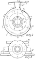
- the stator case according to the invention comprises a main body 2 which has a substantially axial suction inlet 3 and an approximately radial discharge outlet 4.
- the main body 2 made of stamped plate, defines a substantially cylindrical side wall 5 and a front wall 6 which supports, in its central portion 7, an insert sealing ring or shim 8 which has for example an L-shaped or U-shaped cross section.
- the main body 2 is rigidly and sealingly connected to a separator flange 9 which is arranged opposite to the suction inlet and has a central sealing ring W adapted to cooperate with the shaft S of the motor M.
- the main body 2 and the separator flange 9 therefore delimit, with the respective sealing and shim rings, a pressure chamber which accommodates the impeller R.
- a volute 10 is defined partially on the lateral wall 5 and partially on the front wall 6 of the main body 2 made of metal plate and is constituted by an annular recess or channel 11 which extends peripherally to the impeller R.
- the radial transverse cross section of the annular channel 11 rises toward the output of the volute 10, so as to determine, in a per se known manner, the collection and gradual diffusion of the fluid at the output of the impeller.
- At least one portion of the annular recess 11 has a radial transverse cross section which has a substantially constant radial depth and has an axial width which rises uniformly toward the output of the volute.
- the letters A, B, C, D, E, F, G, H indicate radial cross sections of the annular channel 11 which defines the volute 10.
- the outer profiles of said radial transverse cross sections are illustrated in figure 4. From these figures it can be easily understood that in the final portion 1A comprised between the radial cross section D-D and the discharge outlet 4 the annular channel 11 has a radial depth y which is substantially constant and an axial width x which increases toward the discharge outlet, for example with a linear law. Exactly the reverse occurs in the initial portion 12 of the annular channel 11, i.e. the radial depth y rises toward the output of the volute whereas the axial width x is substantially constant.
- An intermediate portion 13 is defined between the end portions 12, 14, and in said portion the radial dimension y and the axial dimension x both increase gradually and in a linear manner.
- the three subsequent portions 11, 12 and 13 are obviously adequately mutually blended so as to avoid flow discontinuity. It is evident that the order of the initial and final portions may be reversed without abandoning the scope of the invention.
- the suction inlet 3 and the discharge outlet 4 are constituted by respective ducts 15, 16 which are made of metal plate, preferably of the same metallic material as the main body 2.
- the channel 15 is shown monolithically integral with the main body 2, whereas in figure 5 it, is constituted by a sleeve 15' which is welded at 17 to the front wall 6 of the main body 2.
- the discharge outlet 16 can be welded at 18 to the outlet of the volute 10.
- Connecting flanges 20, 21, respectively welded to the ends of the ducts 15, 15', 16, are provided.
- the suction inlet 3, and optionally the discharge outlet 4 may have a stiffening structure constituted by a plurality of hollow metal plate ribs suitable for connecting the main body 2 to the respective end flanges.
- said stiffening structure has been illustrated in figure 1 only for the suction inlet 3.
- the ribs 22, which are interposed between the holes 23 of the flange 20, are connected by means of the annular portion 25 to the main body 2 at the welding points 26 and to the flange 20 at the welding points 24.
- the ribs 22 can be made monolithically of stamped plate, so as to be mutually connected with continuity by the central wall 27.
- the radial transverse cross section of the annular channel 11 has been shown with a substantially rectangular shape; however, different shapes, such as for example a semi-elliptical one, may be equally used without abandoning the scope of the invention.
- the materials used for the various parts may be stainless steels or other metallic and synthetic materials, preferably corrosion-resistant ones.
Landscapes
- Engineering & Computer Science (AREA)
- Mechanical Engineering (AREA)
- General Engineering & Computer Science (AREA)
- Structures Of Non-Positive Displacement Pumps (AREA)
- Laminated Bodies (AREA)
- Centrifugal Separators (AREA)
Applications Claiming Priority (2)
| Application Number | Priority Date | Filing Date | Title |
|---|---|---|---|
| IT8985635A IT1234504B (it) | 1989-08-18 | 1989-08-18 | Cassa statorica in lamiera metallica, particolarmente per pompe radiali centrifughe |
| IT8563589 | 1989-08-18 |
Publications (3)
| Publication Number | Publication Date |
|---|---|
| EP0413176A2 EP0413176A2 (en) | 1991-02-20 |
| EP0413176A3 EP0413176A3 (en) | 1992-03-04 |
| EP0413176B1 true EP0413176B1 (en) | 1996-02-28 |
Family
ID=11329355
Family Applications (1)
| Application Number | Title | Priority Date | Filing Date |
|---|---|---|---|
| EP90114318A Expired - Lifetime EP0413176B1 (en) | 1989-08-18 | 1990-07-26 | Metal plate stator case, particularly for radial centrifugal pumps |
Country Status (7)
| Country | Link |
|---|---|
| US (1) | US5069599A (da) |
| EP (1) | EP0413176B1 (da) |
| AT (1) | ATE134745T1 (da) |
| DE (1) | DE69025514T2 (da) |
| DK (1) | DK0413176T3 (da) |
| ES (1) | ES2083986T3 (da) |
| IT (1) | IT1234504B (da) |
Families Citing this family (22)
| Publication number | Priority date | Publication date | Assignee | Title |
|---|---|---|---|---|
| US5235744A (en) * | 1989-07-05 | 1993-08-17 | Ebara Corporation | Method of manufacturing a centrifugal pump casing |
| JP2809487B2 (ja) * | 1989-07-05 | 1998-10-08 | 株式会社荏原製作所 | 遠心ポンプケーシング |
| IT1243113B (it) * | 1990-06-08 | 1994-05-24 | Calpeda A Spa | Diffusore longitudinale periferico per pompa monogirante centrifuga autoadescante |
| JP2676450B2 (ja) * | 1991-01-11 | 1997-11-17 | 株式会社荏原製作所 | 板金製ポンプケーシング |
| US5141397A (en) * | 1991-01-18 | 1992-08-25 | Sullivan John T | Volute housing for a centrifugal fan, blower or the like |
| DE4214026A1 (de) * | 1992-04-29 | 1993-11-04 | Klein Schanzlin & Becker Ag | Pumpengehaeuse |
| DE4324998A1 (de) * | 1993-07-26 | 1995-02-02 | Klein Schanzlin & Becker Ag | Flanschverstärkung |
| DE4331606C1 (de) * | 1993-09-17 | 1994-10-06 | Gutehoffnungshuette Man | Spiralgehäuse für Turbomaschinen |
| US5569017A (en) * | 1994-12-22 | 1996-10-29 | Ametek, Inc. | Fan end bracket for high velocity low pressure blowers |
| JP3226853B2 (ja) * | 1997-09-30 | 2001-11-05 | 株式会社荏原製作所 | ポンプの配管接続部構造 |
| DE69823704T2 (de) * | 1998-10-30 | 2005-05-25 | Yangjiang New Yuehua Stainless Steel Pump Co. Ltd. | Durch schweissen und pressen hergestellte zentrifugalpumpe und deren herstellungsweise |
| US6200090B1 (en) * | 1999-04-12 | 2001-03-13 | Industrial Technology Research Institute | Pump casing for sheet metal pump |
| US6779974B2 (en) * | 2002-12-11 | 2004-08-24 | Polyvane Technology Corp. | Device of a volute channel of a pump |
| US7014422B2 (en) * | 2003-06-13 | 2006-03-21 | American Standard International Inc. | Rounded blower housing with increased airflow |
| DE10347302A1 (de) * | 2003-10-08 | 2005-05-12 | Siemens Ag | Spiralgehäuse für eine Kreiselpumpe |
| US7604457B2 (en) * | 2005-09-13 | 2009-10-20 | Ingersoll-Rand Company | Volute for a centrifugal compressor |
| CN101346085A (zh) * | 2005-12-22 | 2009-01-14 | 皇家飞利浦电子股份有限公司 | 单一服务饮料机 |
| CN100404874C (zh) * | 2006-01-21 | 2008-07-23 | 阳江市新力工业有限公司 | 一种冲压焊接食品泵 |
| DE102009010927B4 (de) | 2009-02-25 | 2021-11-11 | Wilo Se | Pumpengehäuse |
| FR2958324B1 (fr) * | 2010-03-30 | 2015-12-25 | Snecma | Carter de turbomachine rigidifie |
| JP5479316B2 (ja) * | 2010-12-28 | 2014-04-23 | 三菱重工業株式会社 | 遠心圧縮機のスクロール構造 |
| CN115217769A (zh) * | 2021-04-19 | 2022-10-21 | 杭州三花研究院有限公司 | 一种泵 |
Family Cites Families (15)
| Publication number | Priority date | Publication date | Assignee | Title |
|---|---|---|---|---|
| FR125328A (da) * | ||||
| US340120A (en) * | 1886-04-20 | Water-motor | ||
| FR1141182A (fr) * | 1955-02-14 | 1957-08-27 | Charmilles Sa Ateliers | Bâche spirale de machine hydraulique |
| CH442023A (de) * | 1961-10-06 | 1967-08-15 | Ajem Lab Inc | Zentrifugalpumpe |
| DE1703908A1 (de) * | 1968-07-27 | 1972-03-23 | Grundfos As | Pumpengehaeuse fuer Kreiselpumpen |
| DE2047501A1 (de) * | 1970-09-26 | 1972-03-30 | Philipp Hilge Fa | Spiralgehäuse |
| US3846040A (en) * | 1972-06-16 | 1974-11-05 | D Dennis | Blower housing |
| US3856431A (en) * | 1973-10-24 | 1974-12-24 | Singer Co | Side expansion scroll-type blowers |
| JPS5420252A (en) * | 1977-07-15 | 1979-02-15 | Hitachi Ltd | Spiral casing |
| JPS54125318A (en) * | 1978-03-24 | 1979-09-28 | Hitachi Ltd | Supercharger of exhaust steam turbine |
| DE3016438C2 (de) * | 1980-04-29 | 1985-12-19 | Standard Elektrik Lorenz Ag, 7000 Stuttgart | Querstromlüfter |
| US4392779A (en) * | 1980-05-05 | 1983-07-12 | Brunswick Corporation | Marine drive water pump |
| SU941692A1 (ru) * | 1980-11-05 | 1982-07-07 | Специальное конструкторское бюро по конструированию технологического оборудования для обогащения руд | Отвод центробежного насоса |
| GB2172659A (en) * | 1985-03-19 | 1986-09-24 | Austin Rover Group | Cooling liquid pump for internal combustion engine |
| DE3517828A1 (de) * | 1985-05-17 | 1986-11-20 | Klein, Schanzlin & Becker Ag, 6710 Frankenthal | Pumpengehaeuse |
-
1989
- 1989-08-18 IT IT8985635A patent/IT1234504B/it active
-
1990
- 1990-07-26 EP EP90114318A patent/EP0413176B1/en not_active Expired - Lifetime
- 1990-07-26 DE DE69025514T patent/DE69025514T2/de not_active Expired - Fee Related
- 1990-07-26 US US07/558,585 patent/US5069599A/en not_active Expired - Lifetime
- 1990-07-26 DK DK90114318.0T patent/DK0413176T3/da active
- 1990-07-26 AT AT90114318T patent/ATE134745T1/de not_active IP Right Cessation
- 1990-07-26 ES ES90114318T patent/ES2083986T3/es not_active Expired - Lifetime
Also Published As
| Publication number | Publication date |
|---|---|
| DE69025514T2 (de) | 1996-10-31 |
| IT8985635A0 (it) | 1989-08-18 |
| DE69025514D1 (de) | 1996-04-04 |
| EP0413176A3 (en) | 1992-03-04 |
| ATE134745T1 (de) | 1996-03-15 |
| DK0413176T3 (da) | 1996-03-18 |
| EP0413176A2 (en) | 1991-02-20 |
| IT1234504B (it) | 1992-05-18 |
| US5069599A (en) | 1991-12-03 |
| ES2083986T3 (es) | 1996-05-01 |
Similar Documents
| Publication | Publication Date | Title |
|---|---|---|
| EP0413176B1 (en) | Metal plate stator case, particularly for radial centrifugal pumps | |
| KR100192117B1 (ko) | 강판으로 만들어진 펌프용 중간 케이싱과 이를 포함하는 다단원심펌프 | |
| EP0726397B1 (en) | Pump having an improved flow passage | |
| EP0484111B1 (en) | Centrifugal compressor with pipe diffuser and collector | |
| KR100252684B1 (ko) | 강판제 펌프케이싱 | |
| US5618168A (en) | Circulating pump | |
| GB2287509A (en) | Air turbine | |
| US3123010A (en) | Centrifugal pump with thrust balancing means | |
| GB2283059A (en) | Multi stage centrifugal pump with monolithic diffuser and return vane channel ring member | |
| US2753807A (en) | Centrifugal pump and method of manufacture therefor | |
| KR0137654B1 (ko) | 프레싱공정만으로 형성된 팽출부를 갖는 원심펌프 케이싱 | |
| JPS6127598B2 (da) | ||
| EP1216359B1 (en) | Centrifugal pump | |
| US4564334A (en) | Guide wheel for multistage centrifugal pumps | |
| EP0713976A1 (en) | Full-circumferential flow pump | |
| US5522701A (en) | Vertical barrel pump | |
| US4627792A (en) | Rotating flow pump with a feed pump unit formed as an ejector | |
| US4538968A (en) | Motor driven fuel pump | |
| US6017183A (en) | Flow pump | |
| FR2463865A1 (fr) | Compresseur centrifuge a deux etages | |
| EP0442070B1 (en) | Sheet metal pump casing | |
| JPH0647999B2 (ja) | 板金構造うず巻ケーシング | |
| EP0159968A2 (en) | Pneumatic vane pump with body of stamped sheet-metal | |
| CN1079503C (zh) | 液体环式压缩机 | |
| JPH025798A (ja) | 多段遠心形流体機械のディフューザ |
Legal Events
| Date | Code | Title | Description |
|---|---|---|---|
| PUAI | Public reference made under article 153(3) epc to a published international application that has entered the european phase |
Free format text: ORIGINAL CODE: 0009012 |
|
| AK | Designated contracting states |
Kind code of ref document: A2 Designated state(s): AT BE CH DE DK ES FR GB GR IT LI LU NL SE |
|
| PUAL | Search report despatched |
Free format text: ORIGINAL CODE: 0009013 |
|
| AK | Designated contracting states |
Kind code of ref document: A3 Designated state(s): AT BE CH DE DK ES FR GB GR IT LI LU NL SE |
|
| 17P | Request for examination filed |
Effective date: 19920603 |
|
| 17Q | First examination report despatched |
Effective date: 19930722 |
|
| RAP1 | Party data changed (applicant data changed or rights of an application transferred) |
Owner name: EBARA CORPORATION |
|
| GRAH | Despatch of communication of intention to grant a patent |
Free format text: ORIGINAL CODE: EPIDOS IGRA |
|
| GRAA | (expected) grant |
Free format text: ORIGINAL CODE: 0009210 |
|
| AK | Designated contracting states |
Kind code of ref document: B1 Designated state(s): AT BE CH DE DK ES FR GB GR IT LI LU NL SE |
|
| PG25 | Lapsed in a contracting state [announced via postgrant information from national office to epo] |
Ref country code: NL Free format text: LAPSE BECAUSE OF FAILURE TO SUBMIT A TRANSLATION OF THE DESCRIPTION OR TO PAY THE FEE WITHIN THE PRESCRIBED TIME-LIMIT Effective date: 19960228 Ref country code: LI Effective date: 19960228 Ref country code: GR Free format text: LAPSE BECAUSE OF FAILURE TO SUBMIT A TRANSLATION OF THE DESCRIPTION OR TO PAY THE FEE WITHIN THE PRESCRIBED TIME-LIMIT Effective date: 19960228 Ref country code: FR Effective date: 19960228 Ref country code: CH Effective date: 19960228 Ref country code: BE Effective date: 19960228 Ref country code: AT Effective date: 19960228 |
|
| REF | Corresponds to: |
Ref document number: 134745 Country of ref document: AT Date of ref document: 19960315 Kind code of ref document: T |
|
| REG | Reference to a national code |
Ref country code: DK Ref legal event code: T3 |
|
| REF | Corresponds to: |
Ref document number: 69025514 Country of ref document: DE Date of ref document: 19960404 |
|
| ITF | It: translation for a ep patent filed | ||
| REG | Reference to a national code |
Ref country code: ES Ref legal event code: FG2A Ref document number: 2083986 Country of ref document: ES Kind code of ref document: T3 |
|
| PG25 | Lapsed in a contracting state [announced via postgrant information from national office to epo] |
Ref country code: SE Effective date: 19960531 |
|
| EN | Fr: translation not filed | ||
| PG25 | Lapsed in a contracting state [announced via postgrant information from national office to epo] |
Ref country code: GB Effective date: 19960726 |
|
| PG25 | Lapsed in a contracting state [announced via postgrant information from national office to epo] |
Ref country code: LU Free format text: LAPSE BECAUSE OF NON-PAYMENT OF DUE FEES Effective date: 19960731 |
|
| NLV1 | Nl: lapsed or annulled due to failure to fulfill the requirements of art. 29p and 29m of the patents act | ||
| REG | Reference to a national code |
Ref country code: CH Ref legal event code: PL |
|
| PLBE | No opposition filed within time limit |
Free format text: ORIGINAL CODE: 0009261 |
|
| STAA | Information on the status of an ep patent application or granted ep patent |
Free format text: STATUS: NO OPPOSITION FILED WITHIN TIME LIMIT |
|
| 26N | No opposition filed | ||
| GBPC | Gb: european patent ceased through non-payment of renewal fee |
Effective date: 19960726 |
|
| PGFP | Annual fee paid to national office [announced via postgrant information from national office to epo] |
Ref country code: DK Payment date: 20050715 Year of fee payment: 16 |
|
| PGFP | Annual fee paid to national office [announced via postgrant information from national office to epo] |
Ref country code: DE Payment date: 20050721 Year of fee payment: 16 |
|
| PGFP | Annual fee paid to national office [announced via postgrant information from national office to epo] |
Ref country code: ES Payment date: 20050818 Year of fee payment: 16 |
|
| PG25 | Lapsed in a contracting state [announced via postgrant information from national office to epo] |
Ref country code: DK Free format text: LAPSE BECAUSE OF NON-PAYMENT OF DUE FEES Effective date: 20060731 |
|
| PGFP | Annual fee paid to national office [announced via postgrant information from national office to epo] |
Ref country code: IT Payment date: 20060731 Year of fee payment: 17 |
|
| PG25 | Lapsed in a contracting state [announced via postgrant information from national office to epo] |
Ref country code: DE Free format text: LAPSE BECAUSE OF NON-PAYMENT OF DUE FEES Effective date: 20070201 |
|
| REG | Reference to a national code |
Ref country code: DK Ref legal event code: EBP |
|
| REG | Reference to a national code |
Ref country code: ES Ref legal event code: FD2A Effective date: 20060727 |
|
| PG25 | Lapsed in a contracting state [announced via postgrant information from national office to epo] |
Ref country code: ES Free format text: LAPSE BECAUSE OF NON-PAYMENT OF DUE FEES Effective date: 20060727 |
|
| PG25 | Lapsed in a contracting state [announced via postgrant information from national office to epo] |
Ref country code: IT Free format text: LAPSE BECAUSE OF NON-PAYMENT OF DUE FEES Effective date: 20070726 |