EP0412683A1 - Zusatzschwungmasse für eine Kupplung am Getriebeeingang - Google Patents
Zusatzschwungmasse für eine Kupplung am Getriebeeingang Download PDFInfo
- Publication number
- EP0412683A1 EP0412683A1 EP90308218A EP90308218A EP0412683A1 EP 0412683 A1 EP0412683 A1 EP 0412683A1 EP 90308218 A EP90308218 A EP 90308218A EP 90308218 A EP90308218 A EP 90308218A EP 0412683 A1 EP0412683 A1 EP 0412683A1
- Authority
- EP
- European Patent Office
- Prior art keywords
- flywheel
- clutch
- transmission
- transmission input
- engagement
- Prior art date
- Legal status (The legal status is an assumption and is not a legal conclusion. Google has not performed a legal analysis and makes no representation as to the accuracy of the status listed.)
- Granted
Links
- 230000005540 biological transmission Effects 0.000 title claims abstract description 42
- 230000009977 dual effect Effects 0.000 title claims abstract description 10
- 230000007246 mechanism Effects 0.000 description 4
- 230000007935 neutral effect Effects 0.000 description 4
- 230000000712 assembly Effects 0.000 description 3
- 238000000429 assembly Methods 0.000 description 3
- 230000006835 compression Effects 0.000 description 2
- 238000007906 compression Methods 0.000 description 2
- 229910000831 Steel Inorganic materials 0.000 description 1
- 238000013016 damping Methods 0.000 description 1
- 238000010586 diagram Methods 0.000 description 1
- 238000006073 displacement reaction Methods 0.000 description 1
- 238000009499 grossing Methods 0.000 description 1
- 239000007858 starting material Substances 0.000 description 1
- 239000010959 steel Substances 0.000 description 1
Images
Classifications
-
- F—MECHANICAL ENGINEERING; LIGHTING; HEATING; WEAPONS; BLASTING
- F16—ENGINEERING ELEMENTS AND UNITS; GENERAL MEASURES FOR PRODUCING AND MAINTAINING EFFECTIVE FUNCTIONING OF MACHINES OR INSTALLATIONS; THERMAL INSULATION IN GENERAL
- F16D—COUPLINGS FOR TRANSMITTING ROTATION; CLUTCHES; BRAKES
- F16D21/00—Systems comprising a plurality of actuated clutches
- F16D21/08—Serially-arranged clutches interconnecting two shafts only when all the clutches are engaged
-
- B—PERFORMING OPERATIONS; TRANSPORTING
- B60—VEHICLES IN GENERAL
- B60K—ARRANGEMENT OR MOUNTING OF PROPULSION UNITS OR OF TRANSMISSIONS IN VEHICLES; ARRANGEMENT OR MOUNTING OF PLURAL DIVERSE PRIME-MOVERS IN VEHICLES; AUXILIARY DRIVES FOR VEHICLES; INSTRUMENTATION OR DASHBOARDS FOR VEHICLES; ARRANGEMENTS IN CONNECTION WITH COOLING, AIR INTAKE, GAS EXHAUST OR FUEL SUPPLY OF PROPULSION UNITS IN VEHICLES
- B60K17/00—Arrangement or mounting of transmissions in vehicles
- B60K17/02—Arrangement or mounting of transmissions in vehicles characterised by arrangement, location, or kind of clutch
-
- B—PERFORMING OPERATIONS; TRANSPORTING
- B60—VEHICLES IN GENERAL
- B60K—ARRANGEMENT OR MOUNTING OF PROPULSION UNITS OR OF TRANSMISSIONS IN VEHICLES; ARRANGEMENT OR MOUNTING OF PLURAL DIVERSE PRIME-MOVERS IN VEHICLES; AUXILIARY DRIVES FOR VEHICLES; INSTRUMENTATION OR DASHBOARDS FOR VEHICLES; ARRANGEMENTS IN CONNECTION WITH COOLING, AIR INTAKE, GAS EXHAUST OR FUEL SUPPLY OF PROPULSION UNITS IN VEHICLES
- B60K23/00—Arrangement or mounting of control devices for vehicle transmissions, or parts thereof, not otherwise provided for
- B60K23/02—Arrangement or mounting of control devices for vehicle transmissions, or parts thereof, not otherwise provided for for main transmission clutches
-
- F—MECHANICAL ENGINEERING; LIGHTING; HEATING; WEAPONS; BLASTING
- F16—ENGINEERING ELEMENTS AND UNITS; GENERAL MEASURES FOR PRODUCING AND MAINTAINING EFFECTIVE FUNCTIONING OF MACHINES OR INSTALLATIONS; THERMAL INSULATION IN GENERAL
- F16D—COUPLINGS FOR TRANSMITTING ROTATION; CLUTCHES; BRAKES
- F16D13/00—Friction clutches
- F16D13/58—Details
- F16D13/70—Pressure members, e.g. pressure plates, for clutch-plates or lamellae; Guiding arrangements for pressure members
-
- F—MECHANICAL ENGINEERING; LIGHTING; HEATING; WEAPONS; BLASTING
- F16—ENGINEERING ELEMENTS AND UNITS; GENERAL MEASURES FOR PRODUCING AND MAINTAINING EFFECTIVE FUNCTIONING OF MACHINES OR INSTALLATIONS; THERMAL INSULATION IN GENERAL
- F16D—COUPLINGS FOR TRANSMITTING ROTATION; CLUTCHES; BRAKES
- F16D21/00—Systems comprising a plurality of actuated clutches
Definitions
- This invention relates to transmissions having input clutches, and more particularly, to such transmissions and clutches having dual mass flywheels, as, for example, shown in GB Patent Application No 2153929A.
- Dual mass flywheels are used in conjunction with manual transmissions to reduce gear rattle and torsional vibrations, without significantly reducing the shiftability of the transmission. This is usually accomplished by adding a flywheel and a spring damper on the input side or engine side of the input clutch. With the additional flywheel disposed in this location, the engine speed changes during upshifting and downshifting are affected by the increased inertia load. However, the additional flywheel mass does reduce gear rattle during neutral. Connecting the secondary flywheel to the output side of the manual clutch results in increased inertia loading on the transmission synchronizer during ratio interchanges. The last mentioned location has not been desirable, because it requires an increased torque capacity requirement for the synchronizer assemblies disposed in the transmission. This, of course, requires increasing the size and/or complexity of the synchronizer assembly.
- a dual mass flywheel in accordance with the present invention is characterised by the features specified in claim 1.
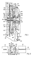
- FIG. 2 shows in block diagram, an engine 10 and a transmission 12. Both of these devices are conventional in design.
- the transmission 12 is preferably of the countershaft type, wherein synchronizers are utilized to change the ratios between a transmission input shaft 14 and a transmission output shaft 16.
- Disposed between the engine 10 and the transmission 12 is an input clutch assembly 18 which is selectively engaged and disengaged by a control mechanism 20 such that power is selectively transmitted from an engine output shaft 22 through the clutch 18 to the transmission input shaft 14.
- the input clutch assembly 18 includes a primary or first flywheel 24 drivingly connected with the engine output shaft 22, a friction plate assembly 26 (friction clutch means), a diaphragm or Belleville spring 28 (spring member), a clutch release bearing 30 and a secondary or second flywheel 32.
- the primary flywheel 24 has disposed on the outer periphery thereof, a starter ring gear 34.
- a clutch housing 36 is secured with the primary flywheel 24 by a plurality of fasteners 38.
- the clutch housing 36 encloses a pressure plate 40 and has secured thereto a plurality of fulcrum or pivot point assemblies 42 which are operatively connected with the Belleville spring 28.
- the friction plate assembly 26 is disposed between the pressure plate 40 and the primary flywheel 24, and is comprised of a pair of (annular) friction pads 44 and 46, a (steel) core plate 48 and a damper assembly 50.
- the damper assembly 50 includes an outer annular member 52 and an inner member 54 which are interconnected by a plurality of helical compression springs 56.
- the helical compression springs 56 permit relative annular displacement between the outer annular member 52 and the inner member 54.
- the inner member 54 has a hub 58 having a spline 60 formed thereon, which meshes with a spline 62 formed on the transmission input shaft 14.
- the transmission input shaft 14 has a pilot end portion 64, which is adapted to pilot in the engine output shaft 22 of the engine 10 in a well known manner.
- the Belleville spring 28 has a plurality of fingers 66 which extend radially inward from the fulcrum point assemblies 42 and are disposed in abutment with an annular thrust bearing 68.
- the Belleville spring 28 also has an outer annular portion 70 which is disposed in abutment with the pressure plate 40.
- the angular thrust bearing 68 is urged into abutment with the clutch release bearing 30, which is slidably disposed on a stub shaft 72 which includes a spline portion 74 drivingly connected with the spline 62.
- the stub shaft 72 is rotatable with the transmission input shaft 14.
- the clutch release bearing 30 is housed in the control mechanism 20, which is comprised of a lever 76, a fulcrum 78 and an actuator 80.
- the actuator 80 is moved linearly through manipulation by an operator to cause the lever 76 to pivot about the fulcrum 78 from the solid line position shown, to the phantom position 76′.
- the Belleville spring 28 will be manipulated such that the outer annular portion 70 will be relieved of forces permitting disengagement between the pressure plate 40 and the friction plate assembly 26.
- the primary flywheel 24 is free to rotate relative to the transmission input shaft 14 so that a ratio change can be accomplished within the transmission 12.
- the stub shaft 72 has formed thereon a cone clutch member 82 (second clutch element).
- the secondary flywheel 32 is rotatably disposed on a bushing 86.
- the secondary flywheel 32 has a conical surface 88 which cooperates with the cone clutch member 82 to provide a friction drive connection between the secondary flywheel 32 and the stub shaft 72, which as previously mentioned, is connected with the transmission input shaft 14.
- the clutch release bearing 30 has a thrust surface 90 which is urged into abutment with the secondary flywheel 32 by the Belleville spring 28 when the lever 76 is in the engaged position shown in solid line. In this position, the secondary flywheel 32 will rotate in unison with the cone clutch member 82 and therefore the transmission input shaft 14.
- the secondary flywheel 32 is included in the driveline to assist in reducing the transmission of engine torsional vibrations to the transmission 12.
- the added mass of the secondary flywheel 32 is also useful when the transmission 12 is positioned for neutral, and the input clutch assembly 18 is engaged. Generally, under this condition, and utilizing only a single flywheel, a rattle condition can occur within the headset of the gears in the transmission 12. The added mass of the secondary flywheel 32 substantially eliminates any gear rattle by greatly attenuating the torsional vibrations in neutral.
- the secondary flywheel 32 provides improved torsional vibration damping reducing neutral gear rattle, and improves ratio interchanging in a synchronizer type transmission.
Applications Claiming Priority (2)
| Application Number | Priority Date | Filing Date | Title |
|---|---|---|---|
| US07/392,163 US5094329A (en) | 1989-08-10 | 1989-08-10 | Dual flywheel for a transmission input clutch |
| US392163 | 1989-08-10 |
Publications (2)
| Publication Number | Publication Date |
|---|---|
| EP0412683A1 true EP0412683A1 (de) | 1991-02-13 |
| EP0412683B1 EP0412683B1 (de) | 1993-09-01 |
Family
ID=23549512
Family Applications (1)
| Application Number | Title | Priority Date | Filing Date |
|---|---|---|---|
| EP90308218A Expired - Lifetime EP0412683B1 (de) | 1989-08-10 | 1990-07-26 | Zusatzschwungmasse für eine Kupplung am Getriebeeingang |
Country Status (4)
| Country | Link |
|---|---|
| US (1) | US5094329A (de) |
| EP (1) | EP0412683B1 (de) |
| JP (1) | JPH0792115B2 (de) |
| DE (1) | DE69003053T2 (de) |
Cited By (5)
| Publication number | Priority date | Publication date | Assignee | Title |
|---|---|---|---|---|
| EP0609491A1 (de) * | 1993-02-05 | 1994-08-10 | Firma Carl Freudenberg | Antriebsstrang eines Kraftfahrzeugs |
| FR2705749A1 (fr) * | 1993-05-28 | 1994-12-02 | Renault | Dispositif d'amortissement des vibrations de torsion dans une chaîne de transmission de puissance. |
| FR2851626A1 (fr) * | 2003-02-20 | 2004-08-27 | Valeo Embrayages | Dispositif de transmission de couple a double volant amortisseur, en particulier pour vehicule automobile. |
| FR2856120A1 (fr) * | 2003-06-10 | 2004-12-17 | Valeo Embrayages | Dispositif de transmission de couple, en particulier pour vehicule automobile |
| US10955049B2 (en) | 2015-11-16 | 2021-03-23 | Per Stensgaard Innovasjon As | Dual-mass flywheel concept for internal combustion engines |
Families Citing this family (7)
| Publication number | Priority date | Publication date | Assignee | Title |
|---|---|---|---|---|
| US5172608A (en) * | 1991-05-22 | 1992-12-22 | General Motors Corporation | Joint connection with a spring clip and nut |
| US5598908A (en) * | 1995-06-05 | 1997-02-04 | Gse, Inc. | Magnetorheological fluid coupling device and torque load simulator system |
| DE102010028938A1 (de) * | 2010-05-12 | 2011-11-17 | Zf Friedrichshafen Ag | Verfahren zum Betreiben eines Antriebsstrangs |
| US8701851B2 (en) | 2010-10-08 | 2014-04-22 | GM Global Technology Operations LLC | Selectable mass flywheel |
| WO2015134219A1 (en) * | 2014-03-06 | 2015-09-11 | Schaeffler Technologies AG & Co. KG | Frusto-conical dual clutch |
| JP2016070339A (ja) * | 2014-09-29 | 2016-05-09 | いすゞ自動車株式会社 | デュアルクラッチ式変速機のクラッチ断接装置 |
| JP5748086B1 (ja) * | 2014-11-28 | 2015-07-15 | 昌克 ▲高▼野 | デュアルクラッチの係脱機構 |
Citations (4)
| Publication number | Priority date | Publication date | Assignee | Title |
|---|---|---|---|---|
| DE3013298A1 (de) * | 1980-04-05 | 1981-10-08 | LuK Lamellen und Kupplungsbau GmbH, 7580 Bühl | Reibungskupplungseinheit |
| DE3404738A1 (de) * | 1984-02-10 | 1985-08-14 | Fichtel & Sachs Ag, 8720 Schweinfurt | Reibungskupplung mit zusatzschwungmasse auf der getriebeeingangswelle |
| DE3607701A1 (de) * | 1986-03-08 | 1987-09-10 | Fichtel & Sachs Ag | Reibungskupplung mit zusatzschwungmasse auf der getriebeeingangswelle |
| DE3816902A1 (de) * | 1987-05-21 | 1988-12-08 | Luk Lamellen & Kupplungsbau | Einrichtung zum daempfen von schwingungen im antriebsstrang eines kfz |
Family Cites Families (3)
| Publication number | Priority date | Publication date | Assignee | Title |
|---|---|---|---|---|
| DE2917137A1 (de) * | 1979-04-27 | 1980-11-06 | Luk Lamellen & Kupplungsbau | Einrichtung zum wahlweisen trennen und verbinden einer drehbaren welle |
| JPH0232890Y2 (de) * | 1984-12-06 | 1990-09-05 | ||
| DE3703123C2 (de) * | 1986-02-27 | 1998-06-04 | Luk Lamellen & Kupplungsbau | Dämpfungseinrichtung |
-
1989
- 1989-08-10 US US07/392,163 patent/US5094329A/en not_active Expired - Lifetime
-
1990
- 1990-07-26 DE DE90308218T patent/DE69003053T2/de not_active Expired - Fee Related
- 1990-07-26 EP EP90308218A patent/EP0412683B1/de not_active Expired - Lifetime
- 1990-08-10 JP JP2213616A patent/JPH0792115B2/ja not_active Expired - Lifetime
Patent Citations (5)
| Publication number | Priority date | Publication date | Assignee | Title |
|---|---|---|---|---|
| DE3013298A1 (de) * | 1980-04-05 | 1981-10-08 | LuK Lamellen und Kupplungsbau GmbH, 7580 Bühl | Reibungskupplungseinheit |
| DE3404738A1 (de) * | 1984-02-10 | 1985-08-14 | Fichtel & Sachs Ag, 8720 Schweinfurt | Reibungskupplung mit zusatzschwungmasse auf der getriebeeingangswelle |
| GB2153929A (en) * | 1984-02-10 | 1985-08-29 | Fichtel & Sachs Ag | Friction clutch with auxiliary flywheel |
| DE3607701A1 (de) * | 1986-03-08 | 1987-09-10 | Fichtel & Sachs Ag | Reibungskupplung mit zusatzschwungmasse auf der getriebeeingangswelle |
| DE3816902A1 (de) * | 1987-05-21 | 1988-12-08 | Luk Lamellen & Kupplungsbau | Einrichtung zum daempfen von schwingungen im antriebsstrang eines kfz |
Cited By (7)
| Publication number | Priority date | Publication date | Assignee | Title |
|---|---|---|---|---|
| EP0609491A1 (de) * | 1993-02-05 | 1994-08-10 | Firma Carl Freudenberg | Antriebsstrang eines Kraftfahrzeugs |
| FR2705749A1 (fr) * | 1993-05-28 | 1994-12-02 | Renault | Dispositif d'amortissement des vibrations de torsion dans une chaîne de transmission de puissance. |
| FR2851626A1 (fr) * | 2003-02-20 | 2004-08-27 | Valeo Embrayages | Dispositif de transmission de couple a double volant amortisseur, en particulier pour vehicule automobile. |
| WO2004076878A2 (fr) * | 2003-02-20 | 2004-09-10 | Valeo Embrayages | Dispositif de transmission de couple a double volant amortisseur, en particulier pour vehicule automobile. |
| WO2004076878A3 (fr) * | 2003-02-20 | 2004-10-21 | Valeo Embrayages | Dispositif de transmission de couple a double volant amortisseur, en particulier pour vehicule automobile. |
| FR2856120A1 (fr) * | 2003-06-10 | 2004-12-17 | Valeo Embrayages | Dispositif de transmission de couple, en particulier pour vehicule automobile |
| US10955049B2 (en) | 2015-11-16 | 2021-03-23 | Per Stensgaard Innovasjon As | Dual-mass flywheel concept for internal combustion engines |
Also Published As
| Publication number | Publication date |
|---|---|
| JPH0396734A (ja) | 1991-04-22 |
| EP0412683B1 (de) | 1993-09-01 |
| DE69003053D1 (de) | 1993-10-07 |
| US5094329A (en) | 1992-03-10 |
| DE69003053T2 (de) | 1993-12-16 |
| JPH0792115B2 (ja) | 1995-10-09 |
Similar Documents
| Publication | Publication Date | Title |
|---|---|---|
| US5094329A (en) | Dual flywheel for a transmission input clutch | |
| JPS5815656B2 (ja) | 変速歯車伝動装置 | |
| US20020129671A1 (en) | Transmission | |
| US3739896A (en) | Friction clutch | |
| US5154683A (en) | Clutch having rotatable friction rings | |
| EP0300792B1 (de) | Kontroll-Einrichtungen für automatischen Gangwechsel | |
| US4890711A (en) | Clutch control system for an automobile vehicle, and a clutch release bearing therefor | |
| US20030066729A1 (en) | Multi-clutch arrangement | |
| US20060096414A1 (en) | Dual clutch assembly for a heavy-duty automotive powertrain | |
| US5795260A (en) | Transmission control system for an electric vehicle | |
| US20120067146A1 (en) | Power unit for vehicle | |
| US4753330A (en) | Multiple clutch system having cam coupler between clutches | |
| JPS6218771B2 (de) | ||
| US5480014A (en) | Double clutch arrangement | |
| GB2125136A (en) | A clutch/gearbox unit for a motor vehicle | |
| US6217475B1 (en) | Dual mass variable inertia flywheel assembly | |
| US4485905A (en) | Centrifugal friction clutch for motor vehicles with three position of operation | |
| US3976174A (en) | Clutch disc with coaxial brake | |
| CA1131941A (en) | Synchronized transmission with torque converter by-pass | |
| GB2160597A (en) | Double clutch for a mechanical, multi-speed automatic transmission in a motor vehicle | |
| JP4176168B2 (ja) | 遠心クラッチ | |
| GB2051267A (en) | Reverse speed shift device for a motor vehicle transmission gearbox | |
| EP0797018A1 (de) | Synchronisiereinrichtung | |
| JPS59103064A (ja) | 車輌用動力伝達装置の減速時制御方法 | |
| JP2002130458A (ja) | 車両用歯車変速機 |
Legal Events
| Date | Code | Title | Description |
|---|---|---|---|
| PUAI | Public reference made under article 153(3) epc to a published international application that has entered the european phase |
Free format text: ORIGINAL CODE: 0009012 |
|
| AK | Designated contracting states |
Kind code of ref document: A1 Designated state(s): DE FR GB |
|
| 17P | Request for examination filed |
Effective date: 19910307 |
|
| 17Q | First examination report despatched |
Effective date: 19920402 |
|
| GRAA | (expected) grant |
Free format text: ORIGINAL CODE: 0009210 |
|
| AK | Designated contracting states |
Kind code of ref document: B1 Designated state(s): DE FR GB |
|
| REF | Corresponds to: |
Ref document number: 69003053 Country of ref document: DE Date of ref document: 19931007 |
|
| ET | Fr: translation filed | ||
| PLBE | No opposition filed within time limit |
Free format text: ORIGINAL CODE: 0009261 |
|
| STAA | Information on the status of an ep patent application or granted ep patent |
Free format text: STATUS: NO OPPOSITION FILED WITHIN TIME LIMIT |
|
| 26N | No opposition filed | ||
| PGFP | Annual fee paid to national office [announced via postgrant information from national office to epo] |
Ref country code: FR Payment date: 20010702 Year of fee payment: 12 |
|
| PGFP | Annual fee paid to national office [announced via postgrant information from national office to epo] |
Ref country code: GB Payment date: 20010703 Year of fee payment: 12 Ref country code: DE Payment date: 20010703 Year of fee payment: 12 |
|
| REG | Reference to a national code |
Ref country code: GB Ref legal event code: IF02 |
|
| PG25 | Lapsed in a contracting state [announced via postgrant information from national office to epo] |
Ref country code: GB Free format text: LAPSE BECAUSE OF NON-PAYMENT OF DUE FEES Effective date: 20020726 |
|
| PG25 | Lapsed in a contracting state [announced via postgrant information from national office to epo] |
Ref country code: DE Free format text: LAPSE BECAUSE OF NON-PAYMENT OF DUE FEES Effective date: 20030201 |
|
| GBPC | Gb: european patent ceased through non-payment of renewal fee |
Effective date: 20020726 |
|
| PG25 | Lapsed in a contracting state [announced via postgrant information from national office to epo] |
Ref country code: FR Free format text: LAPSE BECAUSE OF NON-PAYMENT OF DUE FEES Effective date: 20030331 |
|
| REG | Reference to a national code |
Ref country code: FR Ref legal event code: ST |