EP0411357B1 - Vorrichtung zum Abtrennen einer Flüssigkeit von Feststoffpartikeln - Google Patents
Vorrichtung zum Abtrennen einer Flüssigkeit von Feststoffpartikeln Download PDFInfo
- Publication number
- EP0411357B1 EP0411357B1 EP90113254A EP90113254A EP0411357B1 EP 0411357 B1 EP0411357 B1 EP 0411357B1 EP 90113254 A EP90113254 A EP 90113254A EP 90113254 A EP90113254 A EP 90113254A EP 0411357 B1 EP0411357 B1 EP 0411357B1
- Authority
- EP
- European Patent Office
- Prior art keywords
- solid particles
- liquid
- solid
- edge
- layer
- Prior art date
- Legal status (The legal status is an assumption and is not a legal conclusion. Google has not performed a legal analysis and makes no representation as to the accuracy of the status listed.)
- Expired - Lifetime
Links
Images

Classifications
-
- F—MECHANICAL ENGINEERING; LIGHTING; HEATING; WEAPONS; BLASTING
- F26—DRYING
- F26B—DRYING SOLID MATERIALS OR OBJECTS BY REMOVING LIQUID THEREFROM
- F26B17/00—Machines or apparatus for drying materials in loose, plastic, or fluidised form, e.g. granules, staple fibres, with progressive movement
- F26B17/24—Machines or apparatus for drying materials in loose, plastic, or fluidised form, e.g. granules, staple fibres, with progressive movement with movement performed by shooting or throwing the materials, e.g. after which the materials are subject to impact
-
- B—PERFORMING OPERATIONS; TRANSPORTING
- B01—PHYSICAL OR CHEMICAL PROCESSES OR APPARATUS IN GENERAL
- B01D—SEPARATION
- B01D21/00—Separation of suspended solid particles from liquids by sedimentation
- B01D21/26—Separation of sediment aided by centrifugal force or centripetal force
- B01D21/262—Separation of sediment aided by centrifugal force or centripetal force by using a centrifuge
-
- B—PERFORMING OPERATIONS; TRANSPORTING
- B01—PHYSICAL OR CHEMICAL PROCESSES OR APPARATUS IN GENERAL
- B01D—SEPARATION
- B01D43/00—Separating particles from liquids, or liquids from solids, otherwise than by sedimentation or filtration
Definitions
- the invention relates to a device for separating a liquid from solid particles according to the preamble of claim 1.
- a device of this type is known from DE-A-30 09 332, a number of radial guide surfaces being provided on a rotating disk, which extend straight in the radial direction.
- sand particles are given up, which are distributed through this disc and flung radially outwards against a baffle surface, on which a separation between solids and liquid takes place solely by impact.
- a baffle surface on which a separation between solids and liquid takes place solely by impact.
- Solids e.g. Bottom bundles, clays or mixed sands of different grain sizes can be enveloped by liquid substances of different viscosity, i.e. be completely or partially covered on the free surface.
- Such an envelope can be toxic or contaminative.
- the solid-liquid bond depends on the type-specific adhesion and the surface tension of the respective liquid.
- a liquid contamination can be separated from solid particles by elution or by washing at different temperatures and, for example, also with the addition of specific solvents, but only a differently high dilution effect is achieved without the contamination dissolved in the washing liquid, for example could be completely removed from the surface of a solid particle.
- the invention has for its object to form a device of the type mentioned in such a way that solid particles can be freed from a thin coating of liquid without great effort, which cannot be separated by impact alone.
- this object is achieved by the features in the characterizing part of claim 1.
- the solid particles provided with a coating of a liquid are accelerated to a high speed and then deflected under impact. Due to the different elastic behavior of the liquid and solid particles, the impact of a solid particle on the side opposite the point of impact, the liquid layer is torn open due to the tensile forces in the shell layer, whereupon the liquid due to its surface tension tends to form the smallest surface in relation to the volume , wherein the liquid layer detaches from the solid and forms a drop-shaped formation on the impact surface, while the solid particle is deflected from the impact surface. This results in a separation process which is dependent on the differential path and by means of which a thin liquid layer can be effectively removed from the surface of a solid particle.
- Fig. 1 denotes a solid particle, for example a grain of sand, which is surrounded by a coating layer 2 made of a liquid.
- the thickness of this cladding layer 2 can, for example, be on the order of 40 nm and depends on the respective liquid material, its viscosity and the like.
- the solid particle with the coating layer is accelerated to a relatively high speed in the direction of arrow 3 (state a)) and strikes at a flat angle a baffle surface 4 (state b) in the exemplary embodiment shown, in the illustration according to FIG.
- the angle of incidence ⁇ is preferably less than 12 ° in order to achieve a good separation effect.
- the size of the solid particles can vary, e.g. is the case with sand.
- the mechanical separation process described with reference to FIG. 1 can also be achieved on a straight impact surface 4 by adjusting the impact speed in such a way that the breaking strength of the covering layer is exceeded, but the solid particles are not destroyed.
- An annular baffle 4 is preferably provided in connection with a centrifugal accelerator, which is shown schematically in FIGS. 3 and 4.
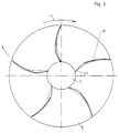
- Fig. 3 shows a section along the line II in Fig. 4 is a plan view of the disc-shaped bottom 7 of a rotor 8, which, starting from a central receiving area 9 to which a solid-liquid mixture is applied from above, radially outwards has running carrier strips 10 which are curved in such a way that the outer trailing edge leads in the direction of rotation (arrow 11) of the inner leading edge 22.
- the solid particles applied perpendicularly from above to the receiving area 9 of the rotor are deflected in the horizontal direction and moved radially outward by the centrifugal force. whereby they come to rest on the carrier strips 10, on which a sliding layer for the solid particles is formed by the simultaneous supply of a liquid.
- the sliding process of the solid particles along a carrier strip 10 is explained in more detail with reference to FIG. 2.
- the solid particles 1 shown in FIG. 2 are provided with the cladding layer 2 to be separated from a liquid which is not shown in detail in FIG. 2.
- the liquid for example water, additionally applied to the rotor with the solid particles forms a sliding layer 12a, 12b along the driver strip 10, on which the solid particles 1, 2 slide radially outward.
- the thickness of the sliding layer 12a, 12b is designed such that the outer partial layer 12b of the sliding layer can flow in relation to the partial layer 12a adhering to the surface of the carrier strip 10.
- the sliding layer 12 is not designed so thick that the solid particles 1, 2 can dip into it.
- the centrifugal acceleration of the solid particles 1, 2 results in a wave-like displacement of the liquid in the direction of acceleration, whereby a starting wedge 12 'forms in front of the solid particles 1, 2, which acts like a cushion and a sagging of the Prevents solid particles on the surface of the driver strip 10 (state a) in Fig. 2).
- the speed of the surface region 12b of the sliding layer increases compared to the layer 12a adhering or resting on the carrier strip 10.
- the sliding layer 12 on the carrier strips 10 is continuously maintained and continuously renewed.
- the suitable thickness of the sliding layer 12 can be determined by reducing or increasing the amount of water applied to the rotor in such a way that there is an unstable range of power consumption for driving the rotor at a predetermined speed of, for example, 1200 rpm. While a constant drive power is required for the rotor in states a) and c) in FIG. 2, increased power must be applied in region b) for the evaporation of the liquid during the formation of hollow suction in region 13. In order to set the suitable thickness of the sliding layer 12, the unstable area of the power consumption is therefore determined and the separation process is carried out in this area.
- FIG. 5 shows the radially outer end of a driver strip 10 which is moved along the impact surface 4 in the direction of the arrow 11, the sliding layer 12 detaching from the driver strip.
- the arrow 20 indicates the direction of detachment of the sliding layer and the arrow 3 indicates the direction of detachment of the solid particles, in which they meet the impact surface 4, such as 1 shows in detail.
- the pressure difference at the driver bars with complete liquid coverage can be achieved with known arithmetic operations, e.g. determined by Laplace's equation and leads to several groups of elementary solutions, e.g. for an assignment of the driver strips with dipoles or with swirl elements.
- the relative flow in the immediate vicinity of the surface of the driver strips is assumed to be zero.
- the detachment of the sliding layer flow at the end of the driver strip does not lead to an immediate compensation of the pressure difference if the detached sliding layer partially evaporates in the extension of the driver strip due to the formation of hollow suction. This effect is usually indefinite.
- an overcavitation profile 17 is essentially provided by a bevel from the pressure side to the suction side. This results in a predetermined hollow suction formation in the area 18.
- the evaporation occurring in the cavitation field 18 outside the end of the carrier strips 10 is followed by condensation.
- the condensation vibration that occurs results in an abrasive effect to prevent possible recontamination of the solid particles 1 freed from their coating layer 2, the shape of the overcavitation profile 17 on the trailing edge of the entraining strip 10 determining the course of the cavitation field 18 in such a way that the abrasive effect of the condensation vibration is in the area of a possible recontamination of the solid particles.
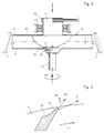
- Fig. 4 shows schematically in a partial section the structure of the rotor 8, which is provided on the top in the middle with a hollow cylindrical feed connector 21 for feeding the solid-liquid mixture.
- the central receiving area 9 under the feed connector 21 is provided with an elevation in the middle and a profile running radially outward so that the mixture supplied is distributed over the circumference of the receiving area 9 and is fed to the leading edge 22 of the carrier strips 10.
- the driver strips 10 are drawn radially inwards in the lower region, so that the lower inlet edge 22 lies near the edge of the central receiving region 9 which is designed in the manner of a plate. As shown in FIG.
- the radially inner inlet edge 22 is slightly advanced in the direction of rotation, so that the solid particles moved outwards from the receiving area 9 by centrifugal action first onto the advanced inlet edge 22 and then continuously upwards and outwards onto the entire surface of the carrier strip 10 be distributed.
- the shape of the curvature of the driver strips 10 corresponds to a sine function.
- the curvature of the driver strips 10 shown in FIG. 3 would extend e.g. intersect the vertical diametral in front of the center and meet the horizontal diagonal to the right of the center, while the radially outer end abuts the vertical diametral from the left.
- the lower lead-in edge 22 is somewhat preferred in the direction of rotation compared to the curvature of the driver strip 10, but it lies in the direction of rotation behind the trailing edge.
- the central receiving area 9 of the rotor 8 is arranged above a feed connector 23 which is attached from below in the center of the rotor and from which channels 24 lead radially outward in the direction of the leading edge 22 of the driver strips.
- Liquid for the formation of a sliding layer is introduced through this feed nozzle 23.
- Steam can also be introduced in addition to the temperature of the solid-liquid mixture applied from above and in particular to adjust the temperature of the liquid forming the sliding layer 12.
- the baffle surface 4 arranged around the circumference of the rotor is expediently designed in the shape of a truncated cone, as shown in FIG. 4, so that the impinging solid particles are also deflected downwards and the liquid parts can be conveniently discharged downwards.
- the inclination can be in the range of 3 °.
- the solid-liquid separation is stabilized below the rotor 8 in a manner known per se by liquor formation.
- the possible number of carrier strips 10 on the rotor 8 essentially depends on the diameter of the receiving area 9, a sufficient distance having to remain between the inlet edges 22 of successive carrier strips so that the solid-liquid mixture can reach the individual carrier strips.
- the rotor can thus be designed as a simple disk with radially extending driver strips.
- the baffle surface 4 surrounding the rotor 8 can be designed as a smooth baffle ring. However, it is also possible to design this baffle surface in an uneven pitch, the maximum wave pitch not exceeding 2 °.
- the applied solid-liquid mixture can be supplied with heat in order to set the appropriate temperature in such a way that steam is added to the air flow passed through the centrifugal accelerator.
- the liquid forming the sliding layer is expediently supplied in the form of pressurized water via a double mechanical seal on the lower feed nozzle 23.
- the described device can e.g. can be used advantageously for the treatment of coal sludge for electricity generation.
Landscapes
- Engineering & Computer Science (AREA)
- Chemical & Material Sciences (AREA)
- Chemical Kinetics & Catalysis (AREA)
- Mechanical Engineering (AREA)
- General Engineering & Computer Science (AREA)
- Centrifugal Separators (AREA)
Description
- Die Erfindung betrifft eine Vorrichtung zum Abtrennen einer Flüssigkeit von Feststoffpartikeln nach dem Oberbegriff des Anspruchs 1.
- Eine Vorrichtung dieser Art ist aus der DE-A-30 09 332 bekannt, wobei auf einer rotierenden Scheibe eine Anzahl von radialen Leitflächen vorgesehen ist, die sich gerade in radialer Richtung erstrecken. In der Mitte dieser Scheibe werden Sandteilchen aufgegeben, die durch diese Scheibe verteilt und radial nach außen gegen eine Prallfläche geschleudert werden, an der eine Trennung zwischen Festkörpern und Flüssigkeit allein durch Prallwirkung erfolgt. Hierdurch ergibt sich nur eine grobe Abtrennung dadurch, daß auf den Feststoffpartikeln eine Hüllschicht der Flüssigkeit verbleibt, insbesondere wenn es sich um eine gut haftende Flüssigkeit mit entsprechender Viskosität handelt.
- Feststoffe, z.B. Bodenkonvolute, Tone oder Mischsande unterschiedlicher Körnung, können von flüssigen Stoffen unterschiedlicher Viskosität umhüllt, d.h. an der freien Oberfläche voll oder teilweise bedeckt sein. Eine solche Hüllschicht kann toxisch oder kontaminativ sein. Die Fest-Flüssig-Bindung ist abhängig von der artspezifischen Adhäsion und der Oberflächenspannung der jeweiligen Flüssigkeit.
- Die Abtrennung einer flüssigen Kontamination von Feststoffpartikeln kann je nach Löslichkeit der Flüssigstoffe eluativ oder durch Waschvorgänge bei unterschiedlichen Temperaturen und z.B. auch unter Zusatz spezifischer Lösungsmittel vorgenommen werden, wobei aber immer nur ein unterschiedlich hoher Verdünnungseffekt erreicht wird, ohne daß die z.B. in der Waschflüssigkeit gelöste Kontamination restlos von der Oberfläche eines Feststoffpartikels abgetragen werden könnte. Es verbleibt immer eine dünne Hüllschicht von unterschiedlicher, ebenfalls artspezifischer Schichtstärke auf der Feststoffoberfläche, die im molekularen Bereich auf der Feststoffoberfläche haftet und aufgrund der Oberflächenspannung und Adhäsion der Flüssigkeit nicht gelöst werden kann.
- Der Erfindung liegt die Aufgabe zugrunde, eine Vorrichtung der eingangs angegebenen Art so aus zubilden, daß Feststoffpartikel ohne großen Aufwand von einer dünnen Hüllschicht aus Flüssigkeit befreit werden können, die man allein durch Prallwirkung nicht abtrennen kann.
- Erfindungsgemäß wird diese Aufgabe durch die Merkmale im kennzeichnenden Teil des Anspruchs 1 gelöst. Die mit einer Hüllschicht aus einer Flüssigkeit versehenen Feststoffpartikel werden auf eine hohe Geschwindigkeit beschleunigt und danach unter Prallwirkung umgelenkt. Aufgrund des unterschiedlichen elastischen Verhaltens von Flüssigkeit und Feststoffpartikel wird beim Aufprall eines Feststoffpartikels auf dessen der Aufprallstelle gegenüberliegenden Seite die Flüssigkeitsschicht aufgrund der auftretenden Zugkräfte in der Hüllschicht aufgerissen, worauf die Flüssigkeit aufgrund ihrer Oberflächenspannung unmittelbar dazu neigt, die im Verhältnis zum Volumen kleinste Oberfläche zu bilden, wobei sich die Flüssigkeitsschicht vom Feststoff löst und sich an der Prallfläche tropfenförmig anlegt, während der Feststoffpartikel von der Prallfläche abgelenkt wird. Hierbei ergibt sich ein differenzwegabhängiger Trennvorgang, mittels dem eine dünne Flüssigkeitsschicht wirksam von der Oberfläche eines Feststoffpartikels gelöst werden kann.
- Vorteilhafte Ausgestaltungen der Erfindung sind in den weiteren Ansprüchen angegeben.
- Eine beispielsweise Ausführungsform der Erfindung wird nachfolgend anhand der Zeichnung näher erläutert. Es zeigen
- Fig. 1
- in schematischer Darstellung einen mit einer Hüllschicht versehenen Feststoffpartikel beim Auftreffen auf eine Prallfläche,
- Fig. 2
- in schematischer Darstellung einen mit einer Hüllschicht versehenen Feststoffpartikel, der längs der Oberfläche einer Mitnehmerleiste eines Zentrifugalbeschleunigers entlanggleitet,
- Fig. 3
- eine Schnittansicht des Rotors längs der Linie I-I in Fig. 4
- Fig. 4
- einen schematischen Teilschnitt durch den Rotor, und
- Fig. 5
- in einer Schnittansicht längs der Linie I-I in Fig. 4 die Austrittskante einer Mitnehmerleiste.
- In Fig. 1 ist mit 1 ein Feststoffpartikel, beispielsweise ein Sandkorn, bezeichnet, das mit einer Hüllschicht 2 aus einer Flüssigkeit umgeben ist. Die Stärke dieser Hüllschicht 2 kann beispielsweise in der Größenordnung von 40 nm liegen und hängt von dem jeweiligen Flüssigkeitsmaterial, dessen Viskosität und dergleichen ab. Der Feststoffpartikel mit Hüllschicht ist in Richtung des Pfeiles 3 auf eine relativ hohe Geschwindigkeit beschleunigt (Zustand a)) und trifft in einem flachen Winkel auf eine bei dem dargestellten Ausführungsbeispiel gekrümmte Prallfläche 4 (Zustand b)), wobei in der Darstellung nach Fig. 1 davon ausgegangen ist, daß die Bewegungsbahn des Feststoffpartikels etwas gekrümmt ist, so daß sich der Richtungspfeil 3a in einen flacheren Winkel zur Tangente an der Prallfläche an der Auftreffstelle entsprechend dem Richtungspfeil 3b ändert. Beim Auftreffen auf der Prallfläche 4 erfährt die Hüllschicht 2 aus Flüssigkeit eine Beschleunigung in Richtung des gestrichelten Pfeiles 5, während der Feststoffpartikel 1 aufgrund seiner höheren Elastizität in Richtung des Pfeiles 6 abgelenkt wird. Die Beschleunigungsrichtung 5 der Flüssigkeitsschicht ist nahezu senkrecht auf die Prallfläche 4 gerichtet, so daß gegenüber der Auftreffstelle die Hüllschicht 2 aufgrund der darin auftretenden Zugkräfte aufreißt. Molekularadhäsion und Oberflächenspannung des flüssigen Materials bewirken eine spontane Verringerung der Verhältniszahl Oberfläche : Volumen, so daß sich die Flüssigkeit vom Feststoff löst, unterstützt durch das schiebeelastische Verhalten des Molekulargitters der Flüssigkeit wie bei 2′ angedeutet, und eine tropfenähnliche Form 2˝ bildet, während der von der Flüssigkeitsschicht vollständig befreite Feststoffpartikel 1 seinen Weg in Richtung des Pfeiles 6 fortsetzt. Der Flüssigkeitstropfen 2˝ bleibt im wesentlichen an der Prallfläche 4 haften und kann an dieser abfließen.
- Vorzugsweise beträgt der Auftreffwinkel α weniger als 12°, um eine gute Trennwirkung zu erzielen. Die Größe der Feststoffpartikel kann unterschiedlich sein, wie dies z.B. bei Sand der Fall ist.
- Der anhand der Fig. 1 beschriebene mechanische Trennvorgang kann auch an einer geraden Prallfläche 4 erzielt werden, indem die Aufprallgeschwindigkeit so eingestellt wird, daß die Bruchfestigkeit der Hüllschicht überschritten, jedoch der Feststoffpartikel nicht zertrümmert wird. Vorzugsweise wird eine ringförmige Prallfläche 4 in Verbindung mit einem Zentrifugalbeschleuniger vorgesehen, der in Fig. 3 und 4 schematisch dargestellt ist.
- Fig. 3 zeigt in einem Schnitt längs der Linie I-I in Fig. 4 eine Draufsicht auf den scheibenförmigen Boden 7 eines Rotors 8, der ausgehend von einem zentralen Aufnahmebereich 9, auf den ein Fest-Flüssig-Gemenge von oben aufgetragen wird, radial nach außen verlaufende Mitnehmerleisten 10 aufweist, die in der Weise gekrümmt sind, daß die außen liegende Austrittskante in Drehrichtung (Pfeil 11) der innen liegenden Einlaufkante 22 vorauseilt. Die senkrecht von oben auf den Aufnahmebereich 9 des Rotors aufgebrachten Feststoffpartikel werden in horizontale Richtung umgelenkt und durch die Zentrifugalkraft radial nach außen bewegt, wobei sie an den Mitnehmerleisten 10 zum Anliegen kommen, auf denen durch gleichzeitige Zuführung einer Flüssigkeit eine Gleitschicht für die Feststoffpartikel ausgebildet wird.
- Anhand von Fig. 2 wird der Gleitvorgang der Feststoffpartikel längs einer Mitnehmerleiste 10 näher erläutert. Die in Fig. 2 wiedergegebenen Feststoffpartikel 1 sind mit der abzutrennenden Hüllschicht 2 aus einer Flüssigkeit versehen, die in Fig. 2 im einzelnen nicht dargestellt ist. Die mit den Feststoffpartikeln auf den Rotor zusätzlich aufgebrachte Flüssigkeit, z.B. Wasser, bildet längs der Mitnehmerleiste 10 eine Gleitschicht 12a, 12b, auf der die Feststoffpartikel 1, 2 radial nach außen gleiten. Die Dicke der Gleitschicht 12a, 12b wird so ausgelegt, daß die äußere Teilschicht 12b der Gleitschicht eine Fließbewegung gegenüber der an der Oberfläche der Mitnehmerleiste 10 haftenden Teilschicht 12a ausführen kann. Andererseits wird die Gleitschicht 12 nicht so dick ausgelegt, daß darin die Feststoffpartikel 1, 2 eintauchen können. Durch die Inkompressibilität der die Gleitschicht bildenden Flüssigkeit ergibt sich bei der zentrifugalen Beschleunigung der Feststoffpartikel 1, 2 eine wellenähnliche Verdrängung der Flüssigkeit in Beschleunigungsrichtung, wodurch sich ein Anlaufkeil 12′ vor dem Feststoffpartikel 1, 2 bildet, der wie ein Kissen wirkt und ein Durchsacken des Feststoffpartikels auf die Oberfläche der Mitnehmerleiste 10 verhindert (Zustand a) in Fig. 2). Im weiteren Verlauf der Beschleunigungsbewegung erhöht sich die Geschwindigkeit des Oberflächenbereichs 12b der Gleitschicht gegenüber der an der Mitnehmerleiste 10 haftenden bzw. ruhenden Schicht 12a. Bei Erreichen einer ausreichenden Differenzgeschwindigkeit zwischen ruhender und fließender Gleitschicht wird innerhalb der Gleitschicht ein Unterdruckbereich 13 aufgebaut, in dem sich durch Dampfbildungen ein Hohlraum ausbildet, während gleichzeitig die Keilhöhe des Anlaufkeils 12′ abgebaut wird. Durch den Abbau des Anlaufkeils 12′ vor dem Feststoffpartikel und die Ausbildung des durch Hohlsogwirkung erzeugten Hohlraums 13 hinter dem Feststoffpartikel wird dieser zusätzlich beschleunigt (Zustand b) in Fig. 2), wie durch den Pfeil 14 schematisch dargestellt, der in Verbindung mit der Ausgangsgeschwindigkeit (Pfeil 15) des Feststoffpartikels zu einer höheren Geschwindigkeit (Pfeil 16) des Feststoffpartikels führt. Im weiteren Verlauf der Gleitbewegung des Feststoffpartikels 1, 2 auf der Gleitschicht 12 (Zustand c) in Fig. 2) gleitet der Feststoffpartikel mit erhöhter Geschwindigkeit in Richtung auf das radial außen liegende Ende der Mitnehmerleiste 10.
- Dadurch, daß mit den Feststoffpartikeln 1, 2 dauernd Flüssigkeit, beispielsweise Wasser, auf den Rotor aufgebracht wird, wird die Gleitschicht 12 auf den Mitnehmerleisten 10 dauernd aufrechterhalten und kontinuierlich erneuert. Die geeignete Dicke der Gleitschicht 12 kann durch Verringerung oder Erhöhung der auf den Rotor aufgebrachten Wassermenge in der Weise ermittelt werden, daß sich für den Antrieb des Rotors bei einer vorgegebenen Drehzahl von beispielsweise 1.200 U/min ein instabiler Bereich der Leistungsaufnahme ergibt. Während in den Zuständen a) und c) in Fig. 2 eine konstante Antriebsleistung für den Rotor erforderlich ist, muß im Zustand b) für die Verdampfung der Flüssigkeit bei der Hohlsogbildung im Bereich 13 erhöhte Leistung aufgebracht werden. Zur Einstellung der geeigneten Dicke der Gleitschicht 12 wird deswegen der instabile Bereich der Leistungsaufnahme ermittelt und in diesem Bereich der Trennvorgang durchgeführt.
- Fig. 5 zeigt das radial außen liegende Ende einer Mitnehmerleiste 10, das an der Prallfläche 4 in Richtung des Pfeils 11 entlangbewegt wird, wobei sich die Gleitschicht 12 von der Mitnehmerleiste ablöst. Durch den Pfeil 20 ist die Ablöserichtung der Gleitschicht und durch den Pfeil 3 die Ablöserichtung der Feststoffpartikel angedeutet, in der sie auf die Prallfläche 4 treffen, wie im einzelnen Fig. 1 zeigt.
- Die Druckdifferenz an den Mitnehmerleisten bei vollständiger Flüssigkeitsbedeckung ist mit bekannten Rechenoperationen, z.B. der Laplace'schen Gleichung bestimmbar und führt zu mehreren Gruppen von Elementarlösungen, z.B. auf eine Belegung der Mitnehmerleisten mit Dipolen oder mit Wirbelelementen. Die Relativströmung in unmittelbarer Nähe der Oberfläche der Mitnehmerleisten ist mit Null anzunehmen. Die Ablösung der Gleitschichtströmung am Ende der Mitnehmerleiste führt nicht zu unmittelbarem Ausgleich der Druckdifferenz, wenn die abgelöste Gleitschicht in Verlängerung der Mitnehmerleiste durch Hohlsogbildung teilweise verdampft. Dieser Effekt ist üblicherweise unbestimmt. Die Berechnung wird dadurch erleichtert, daß die Mitnehmerleisten auf der Ober- und Unterseite von den Scheiben 7, 19 begrenzt und dadurch Kammern gebildet werden, die eine Linearisierung der induzierten Geschwindigkeiten und damit eine Vernachlässigung des Strahlunterdrucks ermöglichen. An der Austrittskante der Mitnehmerleisten wird ein Überkavitationsprofil 17 im wesentlichen durch eine Abschrägung von der Druck- auf die Saugseite vorgesehen. Hierdurch ergibt sich in dem Bereich 18 eine in der Ausrichtung vorbestimmte Hohlsogbildung.
- Auf die im Kavitationsfeld 18 außerhalb des Endes der Mitnehmerleisten 10 auftretende Verdampfung folgt eine Kondensation. Die dabei auftretende Kondensationsvibration ergibt ein abrasive Wirkung zur Verhinderung einer möglichen Rekontamination der von ihrer Hüllschicht 2 befreiten Feststoffpartikel 1, wobei durch die Formgebung des Überkavitationsprofils 17 an der Austrittskante der Mitnehmerleiste 10 der Verlauf des Kavitationsfeldes 18 so vorbestimmt wird, daß die abrasive Wirkung der Kondensationsvibration in dem Bereich einer möglichen Rekontamination der Feststoffpartikel liegt.
- Fig. 4 zeigt schematisch in einem Teilschnitt den Aufbau des Rotors 8, der auf der Oberseite in der Mitte mit einem hohlzylindrischen Zuführstutzen 21 für die Zuführung des Fest-Flüssig-Gemenges versehen ist. Der zentrale Aufnahmebereich 9 unter dem Zuführstutzen 21 ist mit einer Erhöhung in der Mitte und einem radial nach außen verlaufenden Profil versehen, damit das zugeführte Gemenge über den Umfang des Aufnahmebereiches 9 verteilt und der Einlaufkante 22 der Mitnehmerleisten 10 zugeführt wird. Die Mitnehmerleisten 10 sind im unteren Bereich radial nach innen vorgezogen, so daß die untere Einlaufkante 22 nahe dem Rand des tellerartig ausgebildeten zentralen Aufnahmebereiches 9 liegt. Wie Fig. 3 zeigt, ist die radial innen liegende Einlaufkante 22 in Drehrichtung etwas vorgezogen, damit die von dem Aufnahmebereich 9 durch Zentrifugalwirkung nach außen bewegten Feststoffpartikel zunächst auf die vorgezogene Einlaufkante 22 und danach kontinuierlich nach oben und außen auf die gesamte Fläche der Mitnehmerleiste 10 verteilt werden. Die Krümmungsform der Mitnehmerleisten 10 entspricht einer Sinusfunktion. Die in Fig. 3 wiedergegebene Krümmung der Mitnehmerleisten 10 würde in Verlängerung zur Mitte hin z.B. die senkrechte Diametrale vor der Mitte schneiden und rechts von der Mitte auf die horizontale Diagonale treffen, während das radial außen liegende Ende von links an der senkrechten Diametralen anliegt. Die untere Einlaufkante 22 ist zwar in Drehrichtung gegenüber dem Krümmungsverlauf der Mitnehmerleiste 10 etwas vorgezogen, sie liegt aber in Drehrichtung hinter der Austrittskante.
- Der zentrale Aufnahmebereich 9 des Rotors 8 ist über einem von unten in der Mitte des Rotors angebrachten Zuführstutzen 23 angeordnet, von dem aus radial nach außen Kanäle 24 in Richtung auf die Einlaufkante 22 der Mitnehmerleisten führen. Durch diesen Zuführstutzen 23 wird Flüssigkeit für die Gleitschichtbildung eingeführt. Es kann auch zusätzlich Dampf eingeführt werden, um die Temperatur des von oben aufgebrachten Fest-Flüssig-Gemenges und insbesondere die Temperatur der die Gleitschicht 12 bildenden Flüssigkeit einzustellen. Durch die Wärmezufuhr kann die anhand von Fig. 2 erläuterte Hohlsogbildung zur Beschleunigung der Feststoffpartikel besser gesteuert werden.
- Die um den Umfang des Rotors angeordnete Prallfläche 4 wird zweckmäßigerweise etwas kegelstumpfförmig ausgebildet, wie Fig. 4 zeigt, damit die auftreffenden Feststoffpartikel auch nach unten abgelenkt werden und die Flüssigkeitsteile bequem nach unten abgeführt werden können. Die Neigung kann im Bereich von 3°liegen.
- Mit 25 ist eine Lagerung des Rotors 8 und mit 26 ein Riemenantrieb des Rotors in Fig. 4 dargestellt.
- Die Fest-Flüssig-Trennung wird unterhalb des Rotors 8 in an sich bekannter Weise durch Flottenbildung stabilisiert.
- Die mögliche Anzahl der Mitnehmerleisten 10 am Rotor 8 hängt im wesentlichen von dem Durchmesser des Aufnahmebereichs 9 ab, wobei zwischen den Einlaufkanten 22 aufeinanderfolgender Mitnehmerleisten ein ausreichender Abstand verbleiben muß, damit das Fest-Flüssig-Gemenge auf die einzelnen Mitnehmerleisten gelangen kann.
- Es sind verschiedene Abwandlungen der beschriebenen Vorrichtung möglich. So kann der Rotor als einfache Scheibe mit radial verlaufenden Mitnehmerleisten ausgebildet sein. Die den Rotor 8 umgebende Prallfläche 4 kann als glatter Prallring ausgebildet sein. Es ist aber auch möglich, diese Prallfläche in ungerader Teilung gewellt auszubilden, wobei die maximale Wellensteigung 2° nicht übersteigt.
- Dem aufgebrachten Fest-Flüssig-Gemenge kann Wärme zur Einstellung der geeigneten Temperatur in der Weise zugeführt, daß dem durch den Zentrifugalbeschleuniger geführten Luftstrom Dampf beigegeben wird.
- Die die Gleitschicht bildende Flüssigkeit wird zweckmäßigerweise in Form von Druckwasser über eine doppelte Gleitringdichtung an dem unteren Zuführstutzen 23 zugeführt.
- Die beschriebene Vorrichtung kann z.B. zur Aufbereitung von Kohleschlämmen für die Verstromung vorteilhaft eingesetzt werden.
Claims (5)
- Vorrichtung zum Abtrennen einer Flüssigkeit von Feststoffpartikeln, umfassend
eine Scheibe (7) mit über den Umfang verteilten, radial nach außen verlaufenden Mitnehmerleisten (10), wobei in der Mitte der Scheibe ein Aufnahmebereich (9) für das Fest-Flüssig-Gemenge vorgesehen ist, und eine den Außenumfang der Scheibe umgebende Prallfläche (4),
dadurch gekennzeichnet,
daß die Mitnehmerleisten (10) radial nach außen gekrümmt ausgebildet sind, wobei die Austrittskante der Mitnehmerleisten der Einlaufkante in Drehrichtung vorauseilt. - Vorrichtung nach Anspruch 1,
dadurch gekennzeichnet,
daß unter dem Aufnahmebereich (9) ein Zuführstutzen (23) vorgesehen ist, von dem aus radial verlaufende Kanäle (24) bis nahe an die Einlaufkante (22) der Mitnehmerleisten (10) führen. - Vorrichtung nach den Ansprüchen 1 und 2,
dadurch gekennzeichnet,
daß die Mitnehmerleisten (10) auf der Oberseite mit einer scheibenförmigen Abdeckung (19) versehen sind. - Vorrichtung nach den Ansprüchen 1 bis 3,
dadurch gekennzeichnet,
daß die Austrittskante der Mitnehmerleisten (10) auf der Saugseite mit einem Überkavitationsprofil (17) versehen ist. - Vorrichtung nach Anspruch 3,
dadurch gekennzeichnet,
daß die Einlaufkante (22) der Mitnehmerleisten im unteren Bereich radial nach innen bis nahe an den Rand des Aufnahmebereichs (9) vorstehend ausgebildet und in Drehrichtung etwas vorgezogen ist, wobei die Einlaufkante im wesentlichen schräg nach oben und außen zur Abdeckung (19) verläuft.
Applications Claiming Priority (2)
| Application Number | Priority Date | Filing Date | Title |
|---|---|---|---|
| DE3925458 | 1989-08-01 | ||
| DE3925458A DE3925458A1 (de) | 1989-08-01 | 1989-08-01 | Verfahren und vorrichtung zum abtrennen einer fluessigkeit von feststoffpartikeln |
Publications (2)
| Publication Number | Publication Date |
|---|---|
| EP0411357A1 EP0411357A1 (de) | 1991-02-06 |
| EP0411357B1 true EP0411357B1 (de) | 1994-12-07 |
Family
ID=6386297
Family Applications (1)
| Application Number | Title | Priority Date | Filing Date |
|---|---|---|---|
| EP90113254A Expired - Lifetime EP0411357B1 (de) | 1989-08-01 | 1990-07-11 | Vorrichtung zum Abtrennen einer Flüssigkeit von Feststoffpartikeln |
Country Status (4)
| Country | Link |
|---|---|
| EP (1) | EP0411357B1 (de) |
| AT (1) | ATE114995T1 (de) |
| DD (1) | DD296618A5 (de) |
| DE (2) | DE3925458A1 (de) |
Families Citing this family (1)
| Publication number | Priority date | Publication date | Assignee | Title |
|---|---|---|---|---|
| DE4133642C1 (de) * | 1991-10-11 | 1993-02-25 | Alb. Klein Gmbh & Co. Kg, 5241 Niederfischbach, De |
Family Cites Families (2)
| Publication number | Priority date | Publication date | Assignee | Title |
|---|---|---|---|---|
| AT353726B (de) * | 1977-11-28 | 1979-11-26 | Gradwohl Adolf | Vorrichtung zum entwaessern von festgut, insbesondere sand |
| DE3009332A1 (de) * | 1979-03-13 | 1980-10-02 | Yasuro Ito | Verfahren und vorrichtung zur einstellung der auf feinem zuschlagstoff abgeschiedenen fluessigkeitsmenge, sowie verfahren zur herstellung von moertel oder beton |
-
1989
- 1989-08-01 DE DE3925458A patent/DE3925458A1/de not_active Withdrawn
-
1990
- 1990-07-11 EP EP90113254A patent/EP0411357B1/de not_active Expired - Lifetime
- 1990-07-11 DE DE59007913T patent/DE59007913D1/de not_active Expired - Fee Related
- 1990-07-11 AT AT90113254T patent/ATE114995T1/de active
- 1990-07-30 DD DD90343157A patent/DD296618A5/de not_active IP Right Cessation
Also Published As
| Publication number | Publication date |
|---|---|
| DE59007913D1 (de) | 1995-01-19 |
| EP0411357A1 (de) | 1991-02-06 |
| ATE114995T1 (de) | 1994-12-15 |
| DE3925458A1 (de) | 1991-02-07 |
| DD296618A5 (de) | 1991-12-12 |
Similar Documents
| Publication | Publication Date | Title |
|---|---|---|
| DE3590322C2 (de) | Vorrichtung zur Abscheidung von Gas aus einer Fasersuspension | |
| EP0638365B2 (de) | Verfahren und Vorrichtung zur Trennung eines feinkörnigen Feststoffes in zwei Kornfraktionen | |
| DE1782775B2 (de) | Drehluftsichter. Ausscheidung aus: 1507683 | |
| DE1557184A1 (de) | Vorrichtung zum kontinuierlichen Mischen,Homogenisieren und Belueften von pastoesen Massen,insbesondere Schokoladenmassen | |
| DE3622056C2 (de) | ||
| DE3634323C2 (de) | Verfahren und Vorrichtung zur Fliehkrafttrennung eines Flotationssuspensionsgemisches | |
| DE2401524A1 (de) | Zentrifuge | |
| EP0411357B1 (de) | Vorrichtung zum Abtrennen einer Flüssigkeit von Feststoffpartikeln | |
| DE3242653C2 (de) | ||
| DE1913708B2 (de) | Verfahren und Vorrichtung zum Trennen von körnigem Gut | |
| DE3827558C2 (de) | Verfahren und Vorrichtung zum Mahlen von als Suspension gefördertem Mahlgut | |
| DE3626044C2 (de) | ||
| DE19726303A1 (de) | Pulversortiereinrichtung | |
| DE1957607A1 (de) | Abfuehrung von festen Teilchen aus einer Schleudermaschine | |
| DE4326604C2 (de) | Klassiervorrichtung | |
| DE3590172C2 (de) | ||
| DE3602786C2 (de) | ||
| EP0216871B1 (de) | Einrichtung zum kontinuierlichen ausdampfen bzw. ausgasen von flüssigkeiten, welche zur schaumbildung neigen | |
| DE202010008197U1 (de) | Fliehkraftstrahlmühle | |
| DE1481312C (de) | Vorrichtung zum pneumatischen Fördern von körnigem Gut | |
| DD155299A5 (de) | Vollmantel-schneckenzentrifuge | |
| DE340869C (de) | Erzscheider fuer Schaumschwimmverfahren | |
| DE2909037A1 (de) | Vertikalachsiger windsichter | |
| DE2649382A1 (de) | Zentrifugalwindsichter | |
| AT66357B (de) | Zentrifuge für schaumbildende Flüssigkeiten. |
Legal Events
| Date | Code | Title | Description |
|---|---|---|---|
| PUAI | Public reference made under article 153(3) epc to a published international application that has entered the european phase |
Free format text: ORIGINAL CODE: 0009012 |
|
| AK | Designated contracting states |
Kind code of ref document: A1 Designated state(s): AT CH DE FR GB IT LI NL SE |
|
| 17P | Request for examination filed |
Effective date: 19901221 |
|
| 17Q | First examination report despatched |
Effective date: 19920818 |
|
| RAP1 | Party data changed (applicant data changed or rights of an application transferred) |
Owner name: BESITZGESELLSCHAFT MOELLER MBH |
|
| GRAA | (expected) grant |
Free format text: ORIGINAL CODE: 0009210 |
|
| AK | Designated contracting states |
Kind code of ref document: B1 Designated state(s): AT CH DE FR GB IT LI NL SE |
|
| PG25 | Lapsed in a contracting state [announced via postgrant information from national office to epo] |
Ref country code: IT Free format text: LAPSE BECAUSE OF FAILURE TO SUBMIT A TRANSLATION OF THE DESCRIPTION OR TO PAY THE FEE WITHIN THE PRESCRIBED TIME-LIMIT;WARNING: LAPSES OF ITALIAN PATENTS WITH EFFECTIVE DATE BEFORE 2007 MAY HAVE OCCURRED AT ANY TIME BEFORE 2007. THE CORRECT EFFECTIVE DATE MAY BE DIFFERENT FROM THE ONE RECORDED. Effective date: 19941207 Ref country code: NL Effective date: 19941207 |
|
| REF | Corresponds to: |
Ref document number: 114995 Country of ref document: AT Date of ref document: 19941215 Kind code of ref document: T |
|
| REF | Corresponds to: |
Ref document number: 59007913 Country of ref document: DE Date of ref document: 19950119 |
|
| PG25 | Lapsed in a contracting state [announced via postgrant information from national office to epo] |
Ref country code: SE Effective date: 19950307 |
|
| ET | Fr: translation filed | ||
| GBT | Gb: translation of ep patent filed (gb section 77(6)(a)/1977) |
Effective date: 19950314 |
|
| NLV1 | Nl: lapsed or annulled due to failure to fulfill the requirements of art. 29p and 29m of the patents act | ||
| PGFP | Annual fee paid to national office [announced via postgrant information from national office to epo] |
Ref country code: GB Payment date: 19950706 Year of fee payment: 6 |
|
| PGFP | Annual fee paid to national office [announced via postgrant information from national office to epo] |
Ref country code: CH Payment date: 19950713 Year of fee payment: 6 |
|
| PGFP | Annual fee paid to national office [announced via postgrant information from national office to epo] |
Ref country code: FR Payment date: 19950717 Year of fee payment: 6 |
|
| PGFP | Annual fee paid to national office [announced via postgrant information from national office to epo] |
Ref country code: DE Payment date: 19950727 Year of fee payment: 6 |
|
| PGFP | Annual fee paid to national office [announced via postgrant information from national office to epo] |
Ref country code: AT Payment date: 19950728 Year of fee payment: 6 |
|
| PLBE | No opposition filed within time limit |
Free format text: ORIGINAL CODE: 0009261 |
|
| STAA | Information on the status of an ep patent application or granted ep patent |
Free format text: STATUS: NO OPPOSITION FILED WITHIN TIME LIMIT |
|
| 26N | No opposition filed | ||
| PG25 | Lapsed in a contracting state [announced via postgrant information from national office to epo] |
Ref country code: GB Effective date: 19960711 Ref country code: AT Effective date: 19960711 |
|
| PG25 | Lapsed in a contracting state [announced via postgrant information from national office to epo] |
Ref country code: CH Effective date: 19960731 Ref country code: LI Effective date: 19960731 |
|
| GBPC | Gb: european patent ceased through non-payment of renewal fee |
Effective date: 19960711 |
|
| REG | Reference to a national code |
Ref country code: CH Ref legal event code: PL |
|
| PG25 | Lapsed in a contracting state [announced via postgrant information from national office to epo] |
Ref country code: FR Effective date: 19970328 |
|
| PG25 | Lapsed in a contracting state [announced via postgrant information from national office to epo] |
Ref country code: DE Effective date: 19970402 |
|
| REG | Reference to a national code |
Ref country code: FR Ref legal event code: ST |