EP0411256B1 - Kathodenzerstäubungsanlage - Google Patents
Kathodenzerstäubungsanlage Download PDFInfo
- Publication number
- EP0411256B1 EP0411256B1 EP90109079A EP90109079A EP0411256B1 EP 0411256 B1 EP0411256 B1 EP 0411256B1 EP 90109079 A EP90109079 A EP 90109079A EP 90109079 A EP90109079 A EP 90109079A EP 0411256 B1 EP0411256 B1 EP 0411256B1
- Authority
- EP
- European Patent Office
- Prior art keywords
- samples
- container
- rods
- receptacle
- cathode sputtering
- Prior art date
- Legal status (The legal status is an assumption and is not a legal conclusion. Google has not performed a legal analysis and makes no representation as to the accuracy of the status listed.)
- Expired - Lifetime
Links
Images
Classifications
-
- C—CHEMISTRY; METALLURGY
- C23—COATING METALLIC MATERIAL; COATING MATERIAL WITH METALLIC MATERIAL; CHEMICAL SURFACE TREATMENT; DIFFUSION TREATMENT OF METALLIC MATERIAL; COATING BY VACUUM EVAPORATION, BY SPUTTERING, BY ION IMPLANTATION OR BY CHEMICAL VAPOUR DEPOSITION, IN GENERAL; INHIBITING CORROSION OF METALLIC MATERIAL OR INCRUSTATION IN GENERAL
- C23C—COATING METALLIC MATERIAL; COATING MATERIAL WITH METALLIC MATERIAL; SURFACE TREATMENT OF METALLIC MATERIAL BY DIFFUSION INTO THE SURFACE, BY CHEMICAL CONVERSION OR SUBSTITUTION; COATING BY VACUUM EVAPORATION, BY SPUTTERING, BY ION IMPLANTATION OR BY CHEMICAL VAPOUR DEPOSITION, IN GENERAL
- C23C14/00—Coating by vacuum evaporation, by sputtering or by ion implantation of the coating forming material
- C23C14/22—Coating by vacuum evaporation, by sputtering or by ion implantation of the coating forming material characterised by the process of coating
- C23C14/34—Sputtering
- C23C14/3464—Sputtering using more than one target
-
- C—CHEMISTRY; METALLURGY
- C23—COATING METALLIC MATERIAL; COATING MATERIAL WITH METALLIC MATERIAL; CHEMICAL SURFACE TREATMENT; DIFFUSION TREATMENT OF METALLIC MATERIAL; COATING BY VACUUM EVAPORATION, BY SPUTTERING, BY ION IMPLANTATION OR BY CHEMICAL VAPOUR DEPOSITION, IN GENERAL; INHIBITING CORROSION OF METALLIC MATERIAL OR INCRUSTATION IN GENERAL
- C23C—COATING METALLIC MATERIAL; COATING MATERIAL WITH METALLIC MATERIAL; SURFACE TREATMENT OF METALLIC MATERIAL BY DIFFUSION INTO THE SURFACE, BY CHEMICAL CONVERSION OR SUBSTITUTION; COATING BY VACUUM EVAPORATION, BY SPUTTERING, BY ION IMPLANTATION OR BY CHEMICAL VAPOUR DEPOSITION, IN GENERAL
- C23C14/00—Coating by vacuum evaporation, by sputtering or by ion implantation of the coating forming material
- C23C14/22—Coating by vacuum evaporation, by sputtering or by ion implantation of the coating forming material characterised by the process of coating
- C23C14/50—Substrate holders
- C23C14/505—Substrate holders for rotation of the substrates
-
- C—CHEMISTRY; METALLURGY
- C23—COATING METALLIC MATERIAL; COATING MATERIAL WITH METALLIC MATERIAL; CHEMICAL SURFACE TREATMENT; DIFFUSION TREATMENT OF METALLIC MATERIAL; COATING BY VACUUM EVAPORATION, BY SPUTTERING, BY ION IMPLANTATION OR BY CHEMICAL VAPOUR DEPOSITION, IN GENERAL; INHIBITING CORROSION OF METALLIC MATERIAL OR INCRUSTATION IN GENERAL
- C23C—COATING METALLIC MATERIAL; COATING MATERIAL WITH METALLIC MATERIAL; SURFACE TREATMENT OF METALLIC MATERIAL BY DIFFUSION INTO THE SURFACE, BY CHEMICAL CONVERSION OR SUBSTITUTION; COATING BY VACUUM EVAPORATION, BY SPUTTERING, BY ION IMPLANTATION OR BY CHEMICAL VAPOUR DEPOSITION, IN GENERAL
- C23C14/00—Coating by vacuum evaporation, by sputtering or by ion implantation of the coating forming material
- C23C14/22—Coating by vacuum evaporation, by sputtering or by ion implantation of the coating forming material characterised by the process of coating
- C23C14/56—Apparatus specially adapted for continuous coating; Arrangements for maintaining the vacuum, e.g. vacuum locks
Definitions
- the invention relates to a sputtering system according to the preamble of the first claim.
- Such cathode sputtering systems are used to prepare samples with thin coatings, e.g. B. hard materials.
- the cathode sputtering systems have a recipient into which the samples to be coated are introduced.
- One or more cathodes are inserted into the upper part of the recipient, on which the material to be atomized (target) is applied on the inside of the recipient.
- the samples can be moved within the recipient relative to the targets, for example with the aid of a turntable on which the samples are placed.
- the recipient is evacuated and then an inert gas (usually argon) is admitted up to a pressure of the order of 10 -2 mbar.
- an inert gas usually argon
- a negative potential of the order of a few hundred to a thousand volts is applied to the cathodes, the rotary plate or the wall of the recipient being connected as ground, depending on the operating state.
- a glow discharge occurs in the recipient, whereby inert gas ions are formed, which are accelerated in the electric field and strike the target at high speed. Atoms and molecular fragments are knocked out of the surface of the target, which are deposited on the sample, but also in the entire recipient, as a thin layer.
- the targets must be cleaned.
- a target cover generally a sliding or rotatable diaphragm
- the samples are then cleaned. This is done between the turntable and the recipient wall generates a glow charge by applying a negative potential to the turntable, the recipient wall being connected to ground.
- the samples have to be coated one after the other, each time the recipient has to be ventilated for sample exchange and then evacuated again.
- the pumping time is generally 4 to 5 hours.
- sample locks can only be used to a limited extent, particularly for use in laboratory or small series systems, because the positioning of the samples under the target is hardly variable and because the user is restricted with regard to the sample geometry.
- DD-PS 111 409 From DD-PS 111 409 an atomization system is known, in which the targets are attached to a lowerable rotating device and the samples in corresponding processing stations are introduced, whereby several substrates with different materials can be coated in a single process cycle without using a sample lock.
- the number of sample locations corresponds to the number of targets used, so that the available space cannot be fully used for small samples.
- the size of the sample locations is also determined by the size of the targets, which is why larger samples cannot be coated.
- Removable masking covers for sputtering systems is a cover system for a sputtering system is known, wherein covers of partially magnetizable material are present in the recipient, with which substrates can be covered, the covers being able to be lifted and moved by means of electromagnets arranged on a rotatable support arm.
- the object of the invention is to avoid the mentioned disadvantages of known cathode sputtering systems and, in particular, to propose a cathode sputtering system with which several samples can be provided with coatings of different or different thicknesses without the recipient having to be ventilated and evacuated in the meantime. Furthermore, the space available in the recipient for the samples should be able to be fully used with each evacuation even if samples are to be provided with coatings of different or different thicknesses.
- the samples are shielded against an undesired coating using covers which consist partially or entirely of magnetizable material. If all samples are covered, a special covering of the targets for cleaning them before coating the samples, e.g. B. the well-known rotatable aperture.
- a vacuum feedthrough is installed in the upper part of the recipient, through which two are connected of the upper part of the recipient vertically arranged rods of soft magnetic material protrude into the recipient.
- the sample covers can be lifted, set aside and put back again as desired, by using a magnetizing device, e.g. B. an electrical coil or a permanent magnet, are bridged and the turntable is moved to a desired position.
- An electrical coil is particularly preferred as a magnetization device, because any remaining, disruptive residual magnetism of the magnetic material can be easily reduced or completely eliminated by reversing the polarity.
- Another advantage is that, in contrast to the permanent magnet, the magnetic field strength can be varied.
- a high magnetic field strength is only required to lift the covers; after the gap has been overcome, d. H. when the cover is tightened, a considerably lower magnetic field strength is sufficient to hold the cover in place. This makes it possible to drive over other covers, which could otherwise also be raised or at least shifted with a consistently high attraction force.
- the known materials can be used as soft magnetic material for the rods and as magnetizable material for covering the samples.
- soft iron is preferred due to the low residual magnetism.
- the magnetization device In order to impair cathode sputtering as little as possible, the magnetization device should be removed during sputtering.
- the area of the magnetizable material on the sample covers is kept as small as possible.
- a soft iron band is attached to the covers, the dimensions of which are matched to the spacing of the bars.
- the covers can be adapted to different sample geometries. If different sets of covers of different heights are to be used, it is advisable to provide the rods at their ends in the recipient with an axially displaceable sleeve or an axially displaceable pin made of soft magnetic material, so that their length is adapted to the height of the covers before the evacuation can be.
- soft iron bars can be provided with an external thread onto which a soft iron sleeve is partially or fully screwed.
- sleeves with clamping screws or pins etc. which can be inserted into the soft iron rods can also be used.
- the main advantage of the invention is that the known cathode sputtering systems can be easily retrofitted.
- the system according to the invention is simple and reliable to operate, the coating process itself not being influenced. It allows the greatest possible flexibility in the sample geometry, since only sufficiently dimensioned sample covers need to be available, which can be produced easily and inexpensively. The space available in the recipient can be optimally used because the covers can reliably prevent an undesired coating.
- a predetermined order of the coating need not be observed, since any cover can be transported to another place by the magnetizing device and the turntable.
- the number of samples that can be coated with different materials only depends on the number of targets and the available space in the recipient.
- samples can be provided with defined coatings of different thicknesses.
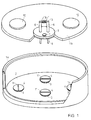
- Figure 1 shows the cathode sputtering system according to the invention.
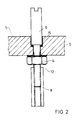
- Figure 2 shows the vacuum feedthrough with one of the two soft iron bars.
- the recipient consists of the underbody 1a and the recipient upper part 1b.
- the turntable 2, with which the samples can be positioned under the targets 10, is attached in the underbody 1a.
- spacer rings 3 are placed on the turntable, which enclose the samples (not shown in the figure).
- Each spacer ring is shielded with a sample cover 4, on the top of which a soft iron strip 11 is screwed on.
- Spacer ring 3 and sample cover 4 can, however, also be connected to one another if a larger-sized coil is used, by means of which the disadvantages of the greater height to be overcome and the additional weight are compensated for.
- the recipient upper part 1b receives the targets 10 and the vacuum feedthrough 5.
- the magnetizable soft iron rods 6 are guided through the vacuum feedthrough. Outside the recipient 1a, 1b, the soft iron rods 6 are bridged by a removable electrical coil 9, which is attached to a yoke 13. At their ends lying inside the recipient, the soft iron rods 6 have an external thread 12, onto which soft iron threaded sleeves 8 are screwed so that they are approx. 1 cm away from the sample cover 4 when the upper part of the recipient is attached.
- a glass pane 7 is also embedded in the vacuum feedthrough, with the aid of which the interior of the recipient can be illuminated and viewed through a side viewing window (not shown).
- the spacer rings 3 are placed on a rotary line 2 on a circular line which corresponds to the possible positions below the targets, leaving a space for storing a sample cover.
- One or more samples to be coated in the same way are positioned within the spacer rings 3. Finally, all spacer rings 3 are covered with the sample covers 4.
- the recipient underbody 1a is closed with the recipient upper part 1b, the electrical coil 9 with the yoke 13 being removed.
- the recipient is then evacuated as far as possible and argon is admitted. Negative potentials are applied to the targets, the turntable being connected to ground. Here the targets are cleaned.
- the soft iron bars 6 are bridged with the yoke 13 and the electrical coil 9.
- the first sample to be coated is positioned under the vacuum feedthrough.
- the sample cover 4 is raised and placed on the free space using the turntable 2. The tension is reduced after lifting off.
- the polarity is reversed briefly to reduce any residual magnetism.
- the exposed sample can be coated with the desired target.
- the corresponding cover is placed over the already coated sample. This is done until all samples are coated.
Landscapes
- Chemical & Material Sciences (AREA)
- Chemical Kinetics & Catalysis (AREA)
- Engineering & Computer Science (AREA)
- Materials Engineering (AREA)
- Mechanical Engineering (AREA)
- Metallurgy (AREA)
- Organic Chemistry (AREA)
- Physical Vapour Deposition (AREA)
Priority Applications (1)
| Application Number | Priority Date | Filing Date | Title |
|---|---|---|---|
| AT90109079T ATE102265T1 (de) | 1989-08-03 | 1990-05-14 | Kathodenzerstaeubungsanlage. |
Applications Claiming Priority (2)
| Application Number | Priority Date | Filing Date | Title |
|---|---|---|---|
| DE3925711 | 1989-08-03 | ||
| DE3925711A DE3925711C1 (enExample) | 1989-08-03 | 1989-08-03 |
Publications (3)
| Publication Number | Publication Date |
|---|---|
| EP0411256A2 EP0411256A2 (de) | 1991-02-06 |
| EP0411256A3 EP0411256A3 (en) | 1991-10-23 |
| EP0411256B1 true EP0411256B1 (de) | 1994-03-02 |
Family
ID=6386449
Family Applications (1)
| Application Number | Title | Priority Date | Filing Date |
|---|---|---|---|
| EP90109079A Expired - Lifetime EP0411256B1 (de) | 1989-08-03 | 1990-05-14 | Kathodenzerstäubungsanlage |
Country Status (3)
| Country | Link |
|---|---|
| EP (1) | EP0411256B1 (enExample) |
| AT (1) | ATE102265T1 (enExample) |
| DE (1) | DE3925711C1 (enExample) |
Family Cites Families (1)
| Publication number | Priority date | Publication date | Assignee | Title |
|---|---|---|---|---|
| DD111409A1 (enExample) * | 1974-05-02 | 1975-02-12 |
-
1989
- 1989-08-03 DE DE3925711A patent/DE3925711C1/de not_active Expired - Lifetime
-
1990
- 1990-05-14 EP EP90109079A patent/EP0411256B1/de not_active Expired - Lifetime
- 1990-05-14 AT AT90109079T patent/ATE102265T1/de not_active IP Right Cessation
Also Published As
| Publication number | Publication date |
|---|---|
| DE3925711C1 (enExample) | 1990-04-19 |
| ATE102265T1 (de) | 1994-03-15 |
| EP0411256A2 (de) | 1991-02-06 |
| EP0411256A3 (en) | 1991-10-23 |
Similar Documents
| Publication | Publication Date | Title |
|---|---|---|
| EP0459137B1 (de) | Vorrichtung zur Beschichtung von Substraten | |
| EP2100322B1 (de) | Vakuumbeschichtungsanlage zur homogenen pvd-beschichtung | |
| DE69231479T2 (de) | Magnetron-Plasma-Bearbeitungsvorrichtung | |
| DE69128195T2 (de) | Ionenplattierung mittels magnetronsputtern | |
| DE3177309T2 (de) | Mittels magnetische Mitteln verbesserte Zerstäubungsquelle. | |
| EP0416241B1 (de) | Vorrichtung zum Beschichten eines Substrats | |
| EP1476891B1 (de) | Vorrichtung und verfahren zum beschichten eines substrates mit magnetischen oder magnetisierbaren werkstoffen | |
| DE3425267A1 (de) | System zum transportieren und behandeln von duennen substraten wie platten oder wafer | |
| DE3920835A1 (de) | Einrichtung zum beschichten von substraten | |
| EP0591706A1 (de) | Kammer für den Transport von Werkstücken | |
| DE4117969C2 (de) | Vakuumkammer | |
| DE3802852C2 (enExample) | ||
| DE112008000912T5 (de) | Magnetronsputtervorrichtung | |
| EP1186681B1 (de) | Vakuumanlage mit koppelbarem Werkstückträger | |
| DE2208032A1 (de) | Zerstäubungsvorrichtung | |
| EP0411256B1 (de) | Kathodenzerstäubungsanlage | |
| DE3880275T2 (de) | Anlage und Verfahren zur Ablagerung einer dünnen Schicht auf ein durchsichtiges Substrat, insbesondere zur Herstellung von Glasscheiben. | |
| DE102006020004A1 (de) | Vorrichtung und Verfahren zur homogenen PVD-Beschichtung | |
| DE69305725T2 (de) | Magnetron-Zerstäubungsvorrichtung und Dünnfilm-Beschichtungsverfahren | |
| DE102009018912A1 (de) | Verfahren zur Erzeugung eines Plasmastrahls sowie Plasmaquelle | |
| DE3837487A1 (de) | Verfahren und vorrichtung zum aetzen von substraten mit einer magnetfeldunterstuetzten niederdruck-entladung | |
| EP0612097A1 (de) | Vorrichtung zum Beschichten eines Substrats | |
| DE4025231C2 (de) | Verfahren und Vorrichtung zum reaktiven Beschichten eines Substrats | |
| EP1754243B1 (de) | Vorrichtung und verfahren zur zerstäubung mit einem bewegbaren planaren target | |
| DE4443740B4 (de) | Vorrichtung zum Beschichten von Substraten |
Legal Events
| Date | Code | Title | Description |
|---|---|---|---|
| PUAI | Public reference made under article 153(3) epc to a published international application that has entered the european phase |
Free format text: ORIGINAL CODE: 0009012 |
|
| AK | Designated contracting states |
Kind code of ref document: A2 Designated state(s): AT CH FR GB LI |
|
| 17P | Request for examination filed |
Effective date: 19910326 |
|
| PUAL | Search report despatched |
Free format text: ORIGINAL CODE: 0009013 |
|
| AK | Designated contracting states |
Kind code of ref document: A3 Designated state(s): AT CH FR GB LI |
|
| 17Q | First examination report despatched |
Effective date: 19930806 |
|
| GRAA | (expected) grant |
Free format text: ORIGINAL CODE: 0009210 |
|
| AK | Designated contracting states |
Kind code of ref document: B1 Designated state(s): AT CH FR GB LI |
|
| REF | Corresponds to: |
Ref document number: 102265 Country of ref document: AT Date of ref document: 19940315 Kind code of ref document: T |
|
| ET | Fr: translation filed | ||
| PGFP | Annual fee paid to national office [announced via postgrant information from national office to epo] |
Ref country code: CH Payment date: 19940428 Year of fee payment: 5 |
|
| PG25 | Lapsed in a contracting state [announced via postgrant information from national office to epo] |
Ref country code: AT Effective date: 19940514 |
|
| PGFP | Annual fee paid to national office [announced via postgrant information from national office to epo] |
Ref country code: GB Payment date: 19940601 Year of fee payment: 5 |
|
| GBT | Gb: translation of ep patent filed (gb section 77(6)(a)/1977) |
Effective date: 19940607 |
|
| RAP2 | Party data changed (patent owner data changed or rights of a patent transferred) |
Owner name: KERNFORSCHUNGSZENTRUM KARLSRUHE GMBH |
|
| PLBE | No opposition filed within time limit |
Free format text: ORIGINAL CODE: 0009261 |
|
| STAA | Information on the status of an ep patent application or granted ep patent |
Free format text: STATUS: NO OPPOSITION FILED WITHIN TIME LIMIT |
|
| PG25 | Lapsed in a contracting state [announced via postgrant information from national office to epo] |
Ref country code: FR Effective date: 19950131 |
|
| 26N | No opposition filed | ||
| REG | Reference to a national code |
Ref country code: FR Ref legal event code: ST |
|
| PG25 | Lapsed in a contracting state [announced via postgrant information from national office to epo] |
Ref country code: GB Effective date: 19950514 |
|
| PG25 | Lapsed in a contracting state [announced via postgrant information from national office to epo] |
Ref country code: LI Effective date: 19950531 Ref country code: CH Effective date: 19950531 |
|
| GBPC | Gb: european patent ceased through non-payment of renewal fee |
Effective date: 19950514 |
|
| REG | Reference to a national code |
Ref country code: CH Ref legal event code: PL |