EP0411256B1 - Cathodic sputtering apparatus - Google Patents
Cathodic sputtering apparatus Download PDFInfo
- Publication number
- EP0411256B1 EP0411256B1 EP90109079A EP90109079A EP0411256B1 EP 0411256 B1 EP0411256 B1 EP 0411256B1 EP 90109079 A EP90109079 A EP 90109079A EP 90109079 A EP90109079 A EP 90109079A EP 0411256 B1 EP0411256 B1 EP 0411256B1
- Authority
- EP
- European Patent Office
- Prior art keywords
- samples
- container
- rods
- receptacle
- cathode sputtering
- Prior art date
- Legal status (The legal status is an assumption and is not a legal conclusion. Google has not performed a legal analysis and makes no representation as to the accuracy of the status listed.)
- Expired - Lifetime
Links
Images
Classifications
-
- C—CHEMISTRY; METALLURGY
- C23—COATING METALLIC MATERIAL; COATING MATERIAL WITH METALLIC MATERIAL; CHEMICAL SURFACE TREATMENT; DIFFUSION TREATMENT OF METALLIC MATERIAL; COATING BY VACUUM EVAPORATION, BY SPUTTERING, BY ION IMPLANTATION OR BY CHEMICAL VAPOUR DEPOSITION, IN GENERAL; INHIBITING CORROSION OF METALLIC MATERIAL OR INCRUSTATION IN GENERAL
- C23C—COATING METALLIC MATERIAL; COATING MATERIAL WITH METALLIC MATERIAL; SURFACE TREATMENT OF METALLIC MATERIAL BY DIFFUSION INTO THE SURFACE, BY CHEMICAL CONVERSION OR SUBSTITUTION; COATING BY VACUUM EVAPORATION, BY SPUTTERING, BY ION IMPLANTATION OR BY CHEMICAL VAPOUR DEPOSITION, IN GENERAL
- C23C14/00—Coating by vacuum evaporation, by sputtering or by ion implantation of the coating forming material
- C23C14/22—Coating by vacuum evaporation, by sputtering or by ion implantation of the coating forming material characterised by the process of coating
- C23C14/34—Sputtering
- C23C14/3464—Sputtering using more than one target
-
- C—CHEMISTRY; METALLURGY
- C23—COATING METALLIC MATERIAL; COATING MATERIAL WITH METALLIC MATERIAL; CHEMICAL SURFACE TREATMENT; DIFFUSION TREATMENT OF METALLIC MATERIAL; COATING BY VACUUM EVAPORATION, BY SPUTTERING, BY ION IMPLANTATION OR BY CHEMICAL VAPOUR DEPOSITION, IN GENERAL; INHIBITING CORROSION OF METALLIC MATERIAL OR INCRUSTATION IN GENERAL
- C23C—COATING METALLIC MATERIAL; COATING MATERIAL WITH METALLIC MATERIAL; SURFACE TREATMENT OF METALLIC MATERIAL BY DIFFUSION INTO THE SURFACE, BY CHEMICAL CONVERSION OR SUBSTITUTION; COATING BY VACUUM EVAPORATION, BY SPUTTERING, BY ION IMPLANTATION OR BY CHEMICAL VAPOUR DEPOSITION, IN GENERAL
- C23C14/00—Coating by vacuum evaporation, by sputtering or by ion implantation of the coating forming material
- C23C14/22—Coating by vacuum evaporation, by sputtering or by ion implantation of the coating forming material characterised by the process of coating
- C23C14/50—Substrate holders
- C23C14/505—Substrate holders for rotation of the substrates
-
- C—CHEMISTRY; METALLURGY
- C23—COATING METALLIC MATERIAL; COATING MATERIAL WITH METALLIC MATERIAL; CHEMICAL SURFACE TREATMENT; DIFFUSION TREATMENT OF METALLIC MATERIAL; COATING BY VACUUM EVAPORATION, BY SPUTTERING, BY ION IMPLANTATION OR BY CHEMICAL VAPOUR DEPOSITION, IN GENERAL; INHIBITING CORROSION OF METALLIC MATERIAL OR INCRUSTATION IN GENERAL
- C23C—COATING METALLIC MATERIAL; COATING MATERIAL WITH METALLIC MATERIAL; SURFACE TREATMENT OF METALLIC MATERIAL BY DIFFUSION INTO THE SURFACE, BY CHEMICAL CONVERSION OR SUBSTITUTION; COATING BY VACUUM EVAPORATION, BY SPUTTERING, BY ION IMPLANTATION OR BY CHEMICAL VAPOUR DEPOSITION, IN GENERAL
- C23C14/00—Coating by vacuum evaporation, by sputtering or by ion implantation of the coating forming material
- C23C14/22—Coating by vacuum evaporation, by sputtering or by ion implantation of the coating forming material characterised by the process of coating
- C23C14/56—Apparatus specially adapted for continuous coating; Arrangements for maintaining the vacuum, e.g. vacuum locks
Definitions
- the invention relates to a sputtering system according to the preamble of the first claim.
- Such cathode sputtering systems are used to prepare samples with thin coatings, e.g. B. hard materials.
- the cathode sputtering systems have a recipient into which the samples to be coated are introduced.
- One or more cathodes are inserted into the upper part of the recipient, on which the material to be atomized (target) is applied on the inside of the recipient.
- the samples can be moved within the recipient relative to the targets, for example with the aid of a turntable on which the samples are placed.
- the recipient is evacuated and then an inert gas (usually argon) is admitted up to a pressure of the order of 10 -2 mbar.
- an inert gas usually argon
- a negative potential of the order of a few hundred to a thousand volts is applied to the cathodes, the rotary plate or the wall of the recipient being connected as ground, depending on the operating state.
- a glow discharge occurs in the recipient, whereby inert gas ions are formed, which are accelerated in the electric field and strike the target at high speed. Atoms and molecular fragments are knocked out of the surface of the target, which are deposited on the sample, but also in the entire recipient, as a thin layer.
- the targets must be cleaned.
- a target cover generally a sliding or rotatable diaphragm
- the samples are then cleaned. This is done between the turntable and the recipient wall generates a glow charge by applying a negative potential to the turntable, the recipient wall being connected to ground.
- the samples have to be coated one after the other, each time the recipient has to be ventilated for sample exchange and then evacuated again.
- the pumping time is generally 4 to 5 hours.
- sample locks can only be used to a limited extent, particularly for use in laboratory or small series systems, because the positioning of the samples under the target is hardly variable and because the user is restricted with regard to the sample geometry.
- DD-PS 111 409 From DD-PS 111 409 an atomization system is known, in which the targets are attached to a lowerable rotating device and the samples in corresponding processing stations are introduced, whereby several substrates with different materials can be coated in a single process cycle without using a sample lock.
- the number of sample locations corresponds to the number of targets used, so that the available space cannot be fully used for small samples.
- the size of the sample locations is also determined by the size of the targets, which is why larger samples cannot be coated.
- Removable masking covers for sputtering systems is a cover system for a sputtering system is known, wherein covers of partially magnetizable material are present in the recipient, with which substrates can be covered, the covers being able to be lifted and moved by means of electromagnets arranged on a rotatable support arm.
- the object of the invention is to avoid the mentioned disadvantages of known cathode sputtering systems and, in particular, to propose a cathode sputtering system with which several samples can be provided with coatings of different or different thicknesses without the recipient having to be ventilated and evacuated in the meantime. Furthermore, the space available in the recipient for the samples should be able to be fully used with each evacuation even if samples are to be provided with coatings of different or different thicknesses.
- the samples are shielded against an undesired coating using covers which consist partially or entirely of magnetizable material. If all samples are covered, a special covering of the targets for cleaning them before coating the samples, e.g. B. the well-known rotatable aperture.
- a vacuum feedthrough is installed in the upper part of the recipient, through which two are connected of the upper part of the recipient vertically arranged rods of soft magnetic material protrude into the recipient.
- the sample covers can be lifted, set aside and put back again as desired, by using a magnetizing device, e.g. B. an electrical coil or a permanent magnet, are bridged and the turntable is moved to a desired position.
- An electrical coil is particularly preferred as a magnetization device, because any remaining, disruptive residual magnetism of the magnetic material can be easily reduced or completely eliminated by reversing the polarity.
- Another advantage is that, in contrast to the permanent magnet, the magnetic field strength can be varied.
- a high magnetic field strength is only required to lift the covers; after the gap has been overcome, d. H. when the cover is tightened, a considerably lower magnetic field strength is sufficient to hold the cover in place. This makes it possible to drive over other covers, which could otherwise also be raised or at least shifted with a consistently high attraction force.
- the known materials can be used as soft magnetic material for the rods and as magnetizable material for covering the samples.
- soft iron is preferred due to the low residual magnetism.
- the magnetization device In order to impair cathode sputtering as little as possible, the magnetization device should be removed during sputtering.
- the area of the magnetizable material on the sample covers is kept as small as possible.
- a soft iron band is attached to the covers, the dimensions of which are matched to the spacing of the bars.
- the covers can be adapted to different sample geometries. If different sets of covers of different heights are to be used, it is advisable to provide the rods at their ends in the recipient with an axially displaceable sleeve or an axially displaceable pin made of soft magnetic material, so that their length is adapted to the height of the covers before the evacuation can be.
- soft iron bars can be provided with an external thread onto which a soft iron sleeve is partially or fully screwed.
- sleeves with clamping screws or pins etc. which can be inserted into the soft iron rods can also be used.
- the main advantage of the invention is that the known cathode sputtering systems can be easily retrofitted.
- the system according to the invention is simple and reliable to operate, the coating process itself not being influenced. It allows the greatest possible flexibility in the sample geometry, since only sufficiently dimensioned sample covers need to be available, which can be produced easily and inexpensively. The space available in the recipient can be optimally used because the covers can reliably prevent an undesired coating.
- a predetermined order of the coating need not be observed, since any cover can be transported to another place by the magnetizing device and the turntable.
- the number of samples that can be coated with different materials only depends on the number of targets and the available space in the recipient.
- samples can be provided with defined coatings of different thicknesses.
- Figure 1 shows the cathode sputtering system according to the invention.
- Figure 2 shows the vacuum feedthrough with one of the two soft iron bars.
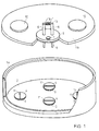
- the recipient consists of the underbody 1a and the recipient upper part 1b.
- the turntable 2, with which the samples can be positioned under the targets 10, is attached in the underbody 1a.
- spacer rings 3 are placed on the turntable, which enclose the samples (not shown in the figure).
- Each spacer ring is shielded with a sample cover 4, on the top of which a soft iron strip 11 is screwed on.
- Spacer ring 3 and sample cover 4 can, however, also be connected to one another if a larger-sized coil is used, by means of which the disadvantages of the greater height to be overcome and the additional weight are compensated for.
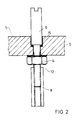
- the recipient upper part 1b receives the targets 10 and the vacuum feedthrough 5.
- the magnetizable soft iron rods 6 are guided through the vacuum feedthrough. Outside the recipient 1a, 1b, the soft iron rods 6 are bridged by a removable electrical coil 9, which is attached to a yoke 13. At their ends lying inside the recipient, the soft iron rods 6 have an external thread 12, onto which soft iron threaded sleeves 8 are screwed so that they are approx. 1 cm away from the sample cover 4 when the upper part of the recipient is attached.
- a glass pane 7 is also embedded in the vacuum feedthrough, with the aid of which the interior of the recipient can be illuminated and viewed through a side viewing window (not shown).
- the spacer rings 3 are placed on a rotary line 2 on a circular line which corresponds to the possible positions below the targets, leaving a space for storing a sample cover.
- One or more samples to be coated in the same way are positioned within the spacer rings 3. Finally, all spacer rings 3 are covered with the sample covers 4.
- the recipient underbody 1a is closed with the recipient upper part 1b, the electrical coil 9 with the yoke 13 being removed.
- the recipient is then evacuated as far as possible and argon is admitted. Negative potentials are applied to the targets, the turntable being connected to ground. Here the targets are cleaned.
- the soft iron bars 6 are bridged with the yoke 13 and the electrical coil 9.
- the first sample to be coated is positioned under the vacuum feedthrough.
- the sample cover 4 is raised and placed on the free space using the turntable 2. The tension is reduced after lifting off.
- the polarity is reversed briefly to reduce any residual magnetism.
- the exposed sample can be coated with the desired target.
- the corresponding cover is placed over the already coated sample. This is done until all samples are coated.
Landscapes
- Chemical & Material Sciences (AREA)
- Chemical Kinetics & Catalysis (AREA)
- Engineering & Computer Science (AREA)
- Materials Engineering (AREA)
- Mechanical Engineering (AREA)
- Metallurgy (AREA)
- Organic Chemistry (AREA)
- Physical Vapour Deposition (AREA)
Abstract
Description
Die Erfindung betrifft eine Kathodenzerstäubungsanlage nach dem Oberbegriff des ersten Patentanspruchs.The invention relates to a sputtering system according to the preamble of the first claim.
Solche Kathodenzerstäubungsanlagen werden verwendet, um Proben mit dünnen Beschichtungen, z. B. von Hartstoffen, zu versehen.Such cathode sputtering systems are used to prepare samples with thin coatings, e.g. B. hard materials.
Die Kathodenzerstäubungsanlagen weisen einen Rezipienten auf, in den die zu beschichtenden Proben eingebracht werden. In das Rezipientenoberteil sind eine oder mehrere Kathoden eingesetzt, auf denen auf der Rezipienteninnenseite das zu zerstäubende Material (Target) aufgebracht ist.The cathode sputtering systems have a recipient into which the samples to be coated are introduced. One or more cathodes are inserted into the upper part of the recipient, on which the material to be atomized (target) is applied on the inside of the recipient.
Die Proben können innerhalb des Rezipienten relativ zu den Targets bewegt werden, beispielsweise mit Hilfe eines Drehtellers, auf dem die Proben abgesetzt werden.The samples can be moved within the recipient relative to the targets, for example with the aid of a turntable on which the samples are placed.
Zur Beschichtung der Proben wird der Rezipient evakuiert und danach ein Inertgas (meist Argon) bis zu einem Druck in der Größenordnung von 10⁻² mbar eingelassen. An den Kathoden wird ein negatives Potential in der Größenordnung von einigen Hundert bis Tausend Volt angelegt, wobei je nach Betriebszustand der Drehteller oder die Wand des Rezipienten als Masse geschaltet ist. Im Rezipienten entsteht eine Glimmentladung, wobei sich Inertgas-Ionen bilden, die im elektrischen Feld beschleunigt werden und mit hoher Geschwindigkeit auf dem Target auftreffen. Aus der Oberfläche des Targets werden Atome und Molekülfragmente herausgeschlagen, die sich auf der Probe, aber auch im gesamten Rezipienten als dünne Schicht niederschlagen. Bevor die Beschichtung der Proben vorgenommen werden kann, müssen die Targets gereinigt werden. Hierzu wird auf eine Target-Abdeckung, im allgemeinen auf eine verschieb- oder drehbare Blende, abgestäubt. Anschließend werden die Proben gereinigt. Dazu wird zwischen Drehteller und Rezipientenwand eine Glimmladung erzeugt, indem an dem Drehteller ein negatives Potential angelegt wird, wobei die Rezipientenwand an Masse liegt.To coat the samples, the recipient is evacuated and then an inert gas (usually argon) is admitted up to a pressure of the order of 10 -2 mbar. A negative potential of the order of a few hundred to a thousand volts is applied to the cathodes, the rotary plate or the wall of the recipient being connected as ground, depending on the operating state. A glow discharge occurs in the recipient, whereby inert gas ions are formed, which are accelerated in the electric field and strike the target at high speed. Atoms and molecular fragments are knocked out of the surface of the target, which are deposited on the sample, but also in the entire recipient, as a thin layer. Before the samples can be coated, the targets must be cleaned. For this purpose, a target cover, generally a sliding or rotatable diaphragm, is dusted. The samples are then cleaned. This is done between the turntable and the recipient wall generates a glow charge by applying a negative potential to the turntable, the recipient wall being connected to ground.
Mit einer solchen Kathodenzerstäubungsanlage können jedoch nicht mehrere Proben mit unterschiedlichen Materialien in einem einzigen Verfahrenszyklus beschichtet werden, da eine Verunreinigung mit den jeweils anderen Schichtmaterialien unvermeidlich ist.With such a sputtering system, however, it is not possible to coat several samples with different materials in a single process cycle, since contamination with the other layer materials is inevitable.
In diesem Fall müssen die Proben nacheinander beschichtet werden, wobei jedesmal der Rezipient zum Probenaustausch belüftet und anschließend wieder evakuiert werden muß. Die Pumpzeit beträgt dabei im allgemeinen 4 bis 5 Stunden.In this case the samples have to be coated one after the other, each time the recipient has to be ventilated for sample exchange and then evacuated again. The pumping time is generally 4 to 5 hours.
Wenn aus einer Reihe von Proben jeweils nur wenige Proben mit der gleichen Beschichtung versehen werden sollen, kann ferner der im Rezipienten für die Proben zur Verfügung stehende Platz nicht optimal genutzt werden.Furthermore, if only a few samples from a series of samples are to be provided with the same coating, the space available in the recipient for the samples cannot be used optimally.
Zwar ist es bekannt, Kathodenzerstäubungsanlagen für die Serienbeschichtung von Proben mit Probenschleusen zu versehen.It is known to provide cathode sputtering systems with sample locks for the serial coating of samples.
Insbesondere für den Einsatz in Labor- oder Kleinserienanlagen sind solche Probenschleusen aber nur bedingt verwendbar, weil die Positionierung der Proben unter dem Target kaum variabel ist und weil der Anwender hinsichtlich der Probengeometrie eingeschränkt ist.However, such sample locks can only be used to a limited extent, particularly for use in laboratory or small series systems, because the positioning of the samples under the target is hardly variable and because the user is restricted with regard to the sample geometry.
Zudem sind solche Probenschleusen u. a. wegen der erforderlichen Zusatzaggregate teuer und mitunter in ihrer Funktion unzuverlässig.In addition, such sample locks u. a. because of the required additional units expensive and sometimes unreliable in their function.
Aus der DD-PS 111 409 ist eine Zerstäubungsanlage bekannt, bei der die Targets auf einer absenkbaren Drehvorrichtung angebracht sind und die Proben in entsprechende Bearbeitungsstationen eingebracht werden, wodurch sich mehrere Substrate mit unterschiedlichen Materialien in einem einzigen Verfahrenszyklus ohne Verwendung einer Probenschleuse beschichten lassen. Bei dieser Zerstäubungsanlage entspricht die Zahl der Probenplätze jedoch der Zahl der verwendeten Targets, so daß sich der vorhandene Platz bei kleinen Proben nicht vollständig nutzen läßt. Die Größe der Probenplätze ist ferner durch die Größe der Targets festgelegt, weshalb größere Proben nicht beschichtet werden können.From DD-PS 111 409 an atomization system is known, in which the targets are attached to a lowerable rotating device and the samples in corresponding processing stations are introduced, whereby several substrates with different materials can be coated in a single process cycle without using a sample lock. In this atomization system, however, the number of sample locations corresponds to the number of targets used, so that the available space cannot be fully used for small samples. The size of the sample locations is also determined by the size of the targets, which is why larger samples cannot be coated.
Aus IBM TECHNICAL DISCLOSURE BULLETIN Bd. 18, Nr. 4, 1. September 1975, Seiten 1284-1285; M. Entner et al. "Removable masking covers for sputtering systems" ist eine Abdeckungssystem für ein Sputteranlage bekannt, wobei im Rezipienten Abdeckungen aus Teilweise magnetisierbarem Material vorhanden sind, mit denen sich Substrate abdecken lassen, wobei die Abdeckungen mittels auf einem drehbaren Trägerarm angeordneten Elektromagneten angehoben und bewegt werden können.From IBM TECHNICAL DISCLOSURE BULLETIN Vol. 18, No. 4, September 1, 1975, pages 1284-1285; M. Entner et al. "Removable masking covers for sputtering systems" is a cover system for a sputtering system is known, wherein covers of partially magnetizable material are present in the recipient, with which substrates can be covered, the covers being able to be lifted and moved by means of electromagnets arranged on a rotatable support arm.
Aufgabe der Erfindung ist, die angesprochenen Nachteile bekannter Kathodenzerstäubungsanlagen zu vermeiden und insbesondere eine Kathodenzerstäubungsanlage vorzuschlagen, mit der mehrere Proben mit unterschiedlichen oder verschieden dicken Beschichtungen versehen werden können, ohne daß der Rezipienten zwischenzeitlich belüftet und wieder evakuiert werden muß. Weiterhin soll sich der im Rezipienten für die Proben vorhandene Platz bei jeder Evakuierung auch dann vollständig nutzen lassen, wenn Proben mit unterschiedlichen oder verschieden dicken Beschichtungen versehen werden sollen.The object of the invention is to avoid the mentioned disadvantages of known cathode sputtering systems and, in particular, to propose a cathode sputtering system with which several samples can be provided with coatings of different or different thicknesses without the recipient having to be ventilated and evacuated in the meantime. Furthermore, the space available in the recipient for the samples should be able to be fully used with each evacuation even if samples are to be provided with coatings of different or different thicknesses.
Zur Lösung der Aufgabe wird erfindungsgemäß eine Kathodenzerstäubungsanlage mit den kennzeichnenden Merkmalen des ersten Patentanspruchs vorgeschlagen.To achieve the object, a cathode sputtering system with the characterizing features of the first claim is proposed.
Die Unteransprüche geben vorteilhafte Ausgestaltungen der Erfindung an.The subclaims indicate advantageous embodiments of the invention.
Erfindungsgemäß werden die Proben vor dem Evakuieren des Rezipienten bis zu ihrer Beschichtung mit Abdeckungen, die teilweise oder ganz aus magnetisierbaren Material bestehen, gegen eine unerwünschte Beschichtung abgeschirmt. Wenn alle Proben abgedeckt werden erübrigt sich eine besondere Abdeckung der Targets für deren Reinigung vor dem Beschichten der Proben, z. B. die bekannte drehbare Blende. Im Rezipientenoberteil ist eine Vakuumdurchführung angebracht, durch die zwei bezüglich des Rezipientenoberteils senkrecht angeordnete Stäbe aus weichmagnetischem Material in den Rezipienten hineinragen. Im evakuierten Rezipienten können die Probenabdeckungen nach Belieben angehoben, beiseite gestellt und wieder zurückgestellt werden, indem die außerhalb des Rezipienten liegenden Enden der Stäbe mit einer Magnetisierungsvorrichtung, z. B. einer elektrischen Spule oder einem Permanentmagneten, überbrückt werden und mit dem Drehteller eine gewünschte Position angefahren wird.According to the invention, before the recipient is evacuated until it is coated, the samples are shielded against an undesired coating using covers which consist partially or entirely of magnetizable material. If all samples are covered, a special covering of the targets for cleaning them before coating the samples, e.g. B. the well-known rotatable aperture. A vacuum feedthrough is installed in the upper part of the recipient, through which two are connected of the upper part of the recipient vertically arranged rods of soft magnetic material protrude into the recipient. In the evacuated recipient, the sample covers can be lifted, set aside and put back again as desired, by using a magnetizing device, e.g. B. an electrical coil or a permanent magnet, are bridged and the turntable is moved to a desired position.
Besonders bevorzugt ist eine elektrische Spule als Magnetisierungsvorrichtung, denn ein eventuell verbleibender, störender Restmagnetismus des magnetischen Materials läßt sich durch Umpolen leicht reduzieren oder ganz beseitigen.An electrical coil is particularly preferred as a magnetization device, because any remaining, disruptive residual magnetism of the magnetic material can be easily reduced or completely eliminated by reversing the polarity.
Ein weiterer Vorteil ist, daß sich im Gegensatz zum Permanentmagneten die magnetische Feldstärke variieren läßt.Another advantage is that, in contrast to the permanent magnet, the magnetic field strength can be varied.
Eine hohe magnetische Feldstärke ist nur zum Anheben der Abdeckungen erforderlich; nach Überwindung des Spalts, d. h. bei angezogener Abdeckung, genügt eine wesentlich geringere magnetische Feldstärke, um die Abdeckung festzuhalten. Damit wird das Überfahren anderer Abdeckungen möglich, die sonst bei gleichbleibend hoher Anziehungskraft ebenfalls angehoben oder zumindest verschoben werden könnten.A high magnetic field strength is only required to lift the covers; after the gap has been overcome, d. H. when the cover is tightened, a considerably lower magnetic field strength is sufficient to hold the cover in place. This makes it possible to drive over other covers, which could otherwise also be raised or at least shifted with a consistently high attraction force.
Als weichmagnetisches Material für die Stäbe und als magnetisierbares Material für die Abdeckungen der Proben können prinzipiell die bekannten Materialien verwendet werden. In beiden Fällen wird wegen des geringen Restmagnetismus Weicheisen bevorzugt.In principle, the known materials can be used as soft magnetic material for the rods and as magnetizable material for covering the samples. In both cases, soft iron is preferred due to the low residual magnetism.
Um die Kathodenzerstäubung möglichst wenig zu beeinträchtigen, soll die Magnetisierungsvorrichtung während des Abstäubens entfernt werden.In order to impair cathode sputtering as little as possible, the magnetization device should be removed during sputtering.
Aus dem gleichen Grund wird die Fläche des magnetisierbaren Materials auf den Probenabdeckungen möglichst klein gehalten. Vorzugsweise wird ein Weicheisenband auf den Abdeckungen angebracht, das in seinen Dimensionen auf den Abstand der Stäbe abgestimmt ist.For the same reason, the area of the magnetizable material on the sample covers is kept as small as possible. Preferably, a soft iron band is attached to the covers, the dimensions of which are matched to the spacing of the bars.
Die Abdeckungen können an verschiedene Probengeometrien angepaßt werden. Sollen verschiedene Sätze unterschiedlich hoher Abdeckungen verwendet werden, empfiehlt es sich, die Stäbe an ihren im Rezipienten liegenden Enden mit einer axial verschiebbaren Hülse oder einem axial verschiebbaren Stift aus weichmagnetischem Material zu versehen, so daß deren Länge vor dem Evakuieren an die Höhe der Abdeckungen angepaßt werden kann. Z. B. können Weicheisenstäbe mit einem Außengewinde versehen werden, auf das eine Weicheisenhülse teilweise oder ganz aufgeschraubt wird. Es können jedoch auch Hülsen mit Klemmschrauben oder in die Weicheisenstäbe einschiebbare Stifte etc. verwendet werden.The covers can be adapted to different sample geometries. If different sets of covers of different heights are to be used, it is advisable to provide the rods at their ends in the recipient with an axially displaceable sleeve or an axially displaceable pin made of soft magnetic material, so that their length is adapted to the height of the covers before the evacuation can be. For example, soft iron bars can be provided with an external thread onto which a soft iron sleeve is partially or fully screwed. However, sleeves with clamping screws or pins etc. which can be inserted into the soft iron rods can also be used.
Der wesentliche Vorteil der Erfindung besteht darin, daß die bekannten Kathodenzerstäubungsanlagen auf einfache Weise nachgerüstet werden können. Die erfindungsgemäße Anlage ist einfach und zuverlässig zu bedienen, wobei der Beschichtungsvorgang selbst nicht beeinflußt wird. Sie erlaubt eine größtmögliche Flexibilität in der Probengeometrie, da lediglich ausreichend dimensionierte Probenabdeckungen zur Verfügung stehen müssen, die sich einfach und preisgünstig herstellen lassen. Der im Rezipienten vorhandene Platz kann optimal genutzt werden, weil durch die Abdeckungen eine unerwünschte Beschichtung zuverlässig verhindert werden kann.The main advantage of the invention is that the known cathode sputtering systems can be easily retrofitted. The system according to the invention is simple and reliable to operate, the coating process itself not being influenced. It allows the greatest possible flexibility in the sample geometry, since only sufficiently dimensioned sample covers need to be available, which can be produced easily and inexpensively. The space available in the recipient can be optimally used because the covers can reliably prevent an undesired coating.
Eine vorgegebene Reihenfolge der Beschichtung braucht nicht eingehalten zu werden, da durch die Magnetisierungsvorrichtung und den Drehteller jede beliebige Abdeckung auf einen anderen Platz transportiert werden kann. Die Zahl der mit verschiedenen Materialien beschichtbaren Proben hängt lediglich von der Zahl der Targets und vom zur Verfügung stehenden Platz im Rezipienten ab. Ferner können Proben mit definierten, unterschiedlich dicken Beschichtungen versehen werden.A predetermined order of the coating need not be observed, since any cover can be transported to another place by the magnetizing device and the turntable. The number of samples that can be coated with different materials only depends on the number of targets and the available space in the recipient. In addition, samples can be provided with defined coatings of different thicknesses.
Die Erfindung wird im folgenden anhand eines Durchführungsbeispiels und der Figuren näher erläutert.The invention is explained in more detail below with the aid of an exemplary embodiment and the figures.
Figur 1 zeigt die erfindungsgemaße Kathodenzerstäubungsanlage.Figure 1 shows the cathode sputtering system according to the invention.
Figur 2 zeigt die Vakuumdurchführung mit einem der beiden Weicheisenstäbe.Figure 2 shows the vacuum feedthrough with one of the two soft iron bars.
Der Rezipient besteht aus dem Unterboden 1a und dem Rezipientenoberteil 1b. Im Unterboden 1a ist der Drehteller 2 angebracht, mit dem sich die Proben unter den Targets 10 positionieren lassen. Vor dem Evakuieren werden auf dem Drehteller Distanzringe 3 abgelegt, die die Proben (in der Figur nicht dargestellt) umschließen. Jeder Distanzring wird mit einer Probenabdeckung 4 abgeschirmt, auf deren Oberseite ein Weicheisenstreifen 11 aufgeschraubt ist. Distanzring 3 und Probenabdeckung 4 können jedoch auch miteinander verbunden sein, wenn eine größer dimensionierte Spule verwendet wird, durch die die Nachteile der größeren zu überwindenden Höhe und des zusätzlichen Gewichts kompensiert werden.The recipient consists of the
Das Rezipientenoberteil 1b nimmt die Targets 10 und die Vakuumdurchführung 5 auf. Durch die Vakuumdurchführung sind die magnetisierbaren Weicheisenstäbe 6 geführt. Außerhalb des Rezipienten 1a, 1b werden die Weicheisenstäbe 6 durch eine entfernbare elektrische Spule 9, die auf einem Joch 13 angebracht ist, überbrückt. An ihren innerhalb des Rezipienten liegenden Enden weisen die Weicheisenstäbe 6 ein Außengewinde 12 auf, auf die Weicheisen-Gewindehülsen 8 so aufgeschraubt sind, daß sie bei aufgesetztem Rezipientenoberteil ca. 1 cm von der Probenabdeckung 4 entfernt sind.The recipient upper part 1b receives the
In die Vakuumdurchführung ist ferner eine Glasscheibe 7 eingelassen, mit deren Hilfe das Rezipienteninnere beleuchtet und durch ein seitliches (nicht dargestelltes) Sichtfenster eingesehen werden kann.A glass pane 7 is also embedded in the vacuum feedthrough, with the aid of which the interior of the recipient can be illuminated and viewed through a side viewing window (not shown).
Vor der Probenbeschichtung werden die Distanzringe 3 auf einer Kreislinie, die den möglichen Positionen unterhalb der Targets entspricht, auf dem Drehteller 2 abgelegt, wobei ein Platz zur Ablage einer Probenabdeckung freibleibt.Before the sample coating, the spacer rings 3 are placed on a
Innerhalb der Distanzringe 3 werden eine oder mehrere gleichartig zu beschichtende Proben positioniert. Schließlich werden sämtliche Distanzringe 3 mit den Probenabdeckungen 4 abgedeckt.One or more samples to be coated in the same way are positioned within the spacer rings 3. Finally, all spacer rings 3 are covered with the sample covers 4.
Der Rezipientenunterboden 1a wird mit dem Rezipientenoberteil 1b verschlossen, wobei die elektrische Spule 9 mit dem Joch 13 abgenommen wird.The
Danach wird der Rezipient so weit wie möglich evakuiert und Argon eingelassen. An die Targets werden negative Potentiale angelegt, wobei der Drehteller an Masse liegt. Hierbei werden die Targets gereinigt.The recipient is then evacuated as far as possible and argon is admitted. Negative potentials are applied to the targets, the turntable being connected to ground. Here the targets are cleaned.
Danach werden mit dem Joch 13 und der elektrischen Spule 9 die Weicheisenstäbe 6 überbrückt. Mit Hilfe des Drehtellers wird die erste zu beschichtende Probe unter die Vakuumdurchführung positioniert. Durch Anlegen einer ausreichenden elektrischen Spannung an die Spule wird die Probenabdeckung 4 angehoben und mit Hilfe des Drehtellers 2 auf dem freigehaltenen Platz abgelegt. Die Spannung wird nach dem Abheben verringert. Zum Ablegen der Abdeckung wird schließlich kurzzeitig umgepolt, um einen eventuellen Restmagnetismus zu verringern.Then the
Danach kann die freigelegte Probe mit dem gewunschten Target beschichtet werden. Vor dem Beschichten der nächsten Probe wird die entsprechende Abdeckung über der bereits beschichteten Probe abgelegt. Auf diese Weise wird verfahren, bis sämtliche Proben beschichtet sind.Then the exposed sample can be coated with the desired target. Before the next sample is coated, the corresponding cover is placed over the already coated sample. This is done until all samples are coated.
- 1a1a
- RezipientenunterbodenRecipient sub-floor
- 1b1b
- RezipientenoberteilRecipient top
- 22nd
- DrehtellerTurntable
- 33rd
- DistanzringSpacer ring
- 44th
- Abdeckungcover
- 55
- VakuumdurchführungVacuum feedthrough
- 66
- WeicheisenstäbeSoft iron bars
- 77
- SichtfensterViewing window
- 88th
- GewindehülsenThreaded sleeves
- 99
- SpuleKitchen sink
- 1010th
- TargetsTargets
- 1111
- WeicheisenstreifenSoft iron strips
- 1212th
- AußengewindeExternal thread
- 1313
- Jochyoke
- 1414
- FeststellmutterLocking nut
- 1515
- O-RingO-ring
Claims (6)
- Cathode sputtering system, havinga) a container for receiving samples to be coated,b) an upper portion (1b) of the container, which contains at least one cathode, to which the material to be sputtered and serving as target (10) is applied,c) a turntable (2) for positioning the samples relative to the target (10), the samples being disposed on the turntable (2), characterised in thatd) the upper portion (1b) of the container is provided with a vacuum passage (5), through which two rods (6), which are disposed vertically relative to the upper portion (1b) of the container and are formed from mildly magnetic material, protrude into the container,e) the ends of the rods (6) situated externally of the container can be bridged by a magnetising device (9, 13),f) at least one covering (4), which is partially or wholly formed from magnetisable material and is freely displaceable in the container, is present in the container, and the samples can be covered by said covering, the sample coverings (4) being raisable by means of the rods (6), in that the ends of the rods (6), situated externally of the container, are bridged by a magnetising device.
- Cathode sputtering system according to claim 1, characterised in that the magnetisable material is soft iron.
- Cathode sputtering system according to claim 2, characterised in that a soft-iron strip (11) is applied to the upper surface of the covering (4) for the samples.
- Cathode sputtering system according to claim 1, characterised in that the magnetising device (9, 13) comprises an electric coil (9) or a permanent magnet.
- Cathode sputtering system according to claim 1, characterised in that the rods (6) are formed from soft iron.
- Cathode sputtering system according to claim 1 or 5, characterised in that, on their ends protruding into the container, the rods (6) are provided with an axially displaceable pin or an axially displaceable sleeve (8).
Priority Applications (1)
| Application Number | Priority Date | Filing Date | Title |
|---|---|---|---|
| AT90109079T ATE102265T1 (en) | 1989-08-03 | 1990-05-14 | CATHODE SPRAYING PLANT. |
Applications Claiming Priority (2)
| Application Number | Priority Date | Filing Date | Title |
|---|---|---|---|
| DE3925711A DE3925711C1 (en) | 1989-08-03 | 1989-08-03 | |
| DE3925711 | 1989-08-03 |
Publications (3)
| Publication Number | Publication Date |
|---|---|
| EP0411256A2 EP0411256A2 (en) | 1991-02-06 |
| EP0411256A3 EP0411256A3 (en) | 1991-10-23 |
| EP0411256B1 true EP0411256B1 (en) | 1994-03-02 |
Family
ID=6386449
Family Applications (1)
| Application Number | Title | Priority Date | Filing Date |
|---|---|---|---|
| EP90109079A Expired - Lifetime EP0411256B1 (en) | 1989-08-03 | 1990-05-14 | Cathodic sputtering apparatus |
Country Status (3)
| Country | Link |
|---|---|
| EP (1) | EP0411256B1 (en) |
| AT (1) | ATE102265T1 (en) |
| DE (1) | DE3925711C1 (en) |
Family Cites Families (1)
| Publication number | Priority date | Publication date | Assignee | Title |
|---|---|---|---|---|
| DD111409A1 (en) * | 1974-05-02 | 1975-02-12 |
-
1989
- 1989-08-03 DE DE3925711A patent/DE3925711C1/de not_active Expired - Fee Related
-
1990
- 1990-05-14 AT AT90109079T patent/ATE102265T1/en not_active IP Right Cessation
- 1990-05-14 EP EP90109079A patent/EP0411256B1/en not_active Expired - Lifetime
Also Published As
| Publication number | Publication date |
|---|---|
| ATE102265T1 (en) | 1994-03-15 |
| EP0411256A2 (en) | 1991-02-06 |
| EP0411256A3 (en) | 1991-10-23 |
| DE3925711C1 (en) | 1990-04-19 |
Similar Documents
| Publication | Publication Date | Title |
|---|---|---|
| EP0459137B1 (en) | Device for coating of substrates | |
| EP0416241B1 (en) | Apparatus for coating a substrate | |
| EP1179611B1 (en) | Chamber for transport of substrates | |
| EP2100322A1 (en) | Vacuum coating unit for homogeneous pvd coating | |
| DE3425267A1 (en) | SYSTEM FOR TRANSPORTING AND TREATING THICKEN SUBSTRATES LIKE PLATES OR WAFER | |
| DE3920835A1 (en) | DEVICE FOR COATING SUBSTRATES | |
| DE4117969C2 (en) | Vacuum chamber | |
| DE3802852C2 (en) | ||
| DE112008000912T5 (en) | magnetron sputtering | |
| EP1476891B1 (en) | Device and method of coating a substrate with magnetic or magnetisable material | |
| WO2007124879A2 (en) | Homogeneous pvd coating device and method | |
| EP1186681B1 (en) | Vacuum treatment apparatus having dockable substrate holder | |
| DE2208032A1 (en) | Atomizing device | |
| EP0504477B1 (en) | Substrate coating device | |
| DE10196150T5 (en) | Magnetron sputtering | |
| EP0411256B1 (en) | Cathodic sputtering apparatus | |
| EP0316523A2 (en) | Control for sputtering according to the magnetron principle | |
| EP1754243B1 (en) | Device and method for sputtering with the aid of a displaceable planar target | |
| EP0612097A1 (en) | Substrate coating device | |
| DE4025231C2 (en) | Method and device for reactive coating of a substrate | |
| DE3837487A1 (en) | METHOD AND DEVICE FOR ETCHING SUBSTRATES WITH A MAGNETIC FIELD SUPPORTED LOW PRESSURE DISCHARGE | |
| DE4239843A1 (en) | Appts for sputter coating substrates - using microwave resonator to improve coating | |
| DE60129975T2 (en) | DEVICE FOR PERFORMING AT LEAST ONE TREATMENT OF A SUBSTRATE | |
| DE4443740B4 (en) | Device for coating substrates | |
| DE4419167B4 (en) | Device for coating a substrate |
Legal Events
| Date | Code | Title | Description |
|---|---|---|---|
| PUAI | Public reference made under article 153(3) epc to a published international application that has entered the european phase |
Free format text: ORIGINAL CODE: 0009012 |
|
| AK | Designated contracting states |
Kind code of ref document: A2 Designated state(s): AT CH FR GB LI |
|
| 17P | Request for examination filed |
Effective date: 19910326 |
|
| PUAL | Search report despatched |
Free format text: ORIGINAL CODE: 0009013 |
|
| AK | Designated contracting states |
Kind code of ref document: A3 Designated state(s): AT CH FR GB LI |
|
| 17Q | First examination report despatched |
Effective date: 19930806 |
|
| GRAA | (expected) grant |
Free format text: ORIGINAL CODE: 0009210 |
|
| AK | Designated contracting states |
Kind code of ref document: B1 Designated state(s): AT CH FR GB LI |
|
| REF | Corresponds to: |
Ref document number: 102265 Country of ref document: AT Date of ref document: 19940315 Kind code of ref document: T |
|
| ET | Fr: translation filed | ||
| PGFP | Annual fee paid to national office [announced via postgrant information from national office to epo] |
Ref country code: CH Payment date: 19940428 Year of fee payment: 5 |
|
| PG25 | Lapsed in a contracting state [announced via postgrant information from national office to epo] |
Ref country code: AT Effective date: 19940514 |
|
| PGFP | Annual fee paid to national office [announced via postgrant information from national office to epo] |
Ref country code: GB Payment date: 19940601 Year of fee payment: 5 |
|
| GBT | Gb: translation of ep patent filed (gb section 77(6)(a)/1977) |
Effective date: 19940607 |
|
| RAP2 | Party data changed (patent owner data changed or rights of a patent transferred) |
Owner name: KERNFORSCHUNGSZENTRUM KARLSRUHE GMBH |
|
| PLBE | No opposition filed within time limit |
Free format text: ORIGINAL CODE: 0009261 |
|
| STAA | Information on the status of an ep patent application or granted ep patent |
Free format text: STATUS: NO OPPOSITION FILED WITHIN TIME LIMIT |
|
| PG25 | Lapsed in a contracting state [announced via postgrant information from national office to epo] |
Ref country code: FR Effective date: 19950131 |
|
| 26N | No opposition filed | ||
| REG | Reference to a national code |
Ref country code: FR Ref legal event code: ST |
|
| PG25 | Lapsed in a contracting state [announced via postgrant information from national office to epo] |
Ref country code: GB Effective date: 19950514 |
|
| PG25 | Lapsed in a contracting state [announced via postgrant information from national office to epo] |
Ref country code: LI Effective date: 19950531 Ref country code: CH Effective date: 19950531 |
|
| GBPC | Gb: european patent ceased through non-payment of renewal fee |
Effective date: 19950514 |
|
| REG | Reference to a national code |
Ref country code: CH Ref legal event code: PL |