EP0410896B1 - Verbesserungen an hydraulischen Schwingungsdämpfern - Google Patents
Verbesserungen an hydraulischen Schwingungsdämpfern Download PDFInfo
- Publication number
- EP0410896B1 EP0410896B1 EP90402175A EP90402175A EP0410896B1 EP 0410896 B1 EP0410896 B1 EP 0410896B1 EP 90402175 A EP90402175 A EP 90402175A EP 90402175 A EP90402175 A EP 90402175A EP 0410896 B1 EP0410896 B1 EP 0410896B1
- Authority
- EP
- European Patent Office
- Prior art keywords
- piston
- case
- damping device
- rigid
- foot
- Prior art date
- Legal status (The legal status is an assumption and is not a legal conclusion. Google has not performed a legal analysis and makes no representation as to the accuracy of the status listed.)
- Expired - Lifetime
Links
Images

Classifications
-
- F—MECHANICAL ENGINEERING; LIGHTING; HEATING; WEAPONS; BLASTING
- F16—ENGINEERING ELEMENTS AND UNITS; GENERAL MEASURES FOR PRODUCING AND MAINTAINING EFFECTIVE FUNCTIONING OF MACHINES OR INSTALLATIONS; THERMAL INSULATION IN GENERAL
- F16F—SPRINGS; SHOCK-ABSORBERS; MEANS FOR DAMPING VIBRATION
- F16F13/00—Units comprising springs of the non-fluid type as well as vibration-dampers, shock-absorbers, or fluid springs
- F16F13/04—Units comprising springs of the non-fluid type as well as vibration-dampers, shock-absorbers, or fluid springs comprising both a plastics spring and a damper, e.g. a friction damper
- F16F13/06—Units comprising springs of the non-fluid type as well as vibration-dampers, shock-absorbers, or fluid springs comprising both a plastics spring and a damper, e.g. a friction damper the damper being a fluid damper, e.g. the plastics spring not forming a part of the wall of the fluid chamber of the damper
- F16F13/08—Units comprising springs of the non-fluid type as well as vibration-dampers, shock-absorbers, or fluid springs comprising both a plastics spring and a damper, e.g. a friction damper the damper being a fluid damper, e.g. the plastics spring not forming a part of the wall of the fluid chamber of the damper the plastics spring forming at least a part of the wall of the fluid chamber of the damper
-
- F—MECHANICAL ENGINEERING; LIGHTING; HEATING; WEAPONS; BLASTING
- F16—ENGINEERING ELEMENTS AND UNITS; GENERAL MEASURES FOR PRODUCING AND MAINTAINING EFFECTIVE FUNCTIONING OF MACHINES OR INSTALLATIONS; THERMAL INSULATION IN GENERAL
- F16F—SPRINGS; SHOCK-ABSORBERS; MEANS FOR DAMPING VIBRATION
- F16F13/00—Units comprising springs of the non-fluid type as well as vibration-dampers, shock-absorbers, or fluid springs
- F16F13/04—Units comprising springs of the non-fluid type as well as vibration-dampers, shock-absorbers, or fluid springs comprising both a plastics spring and a damper, e.g. a friction damper
- F16F13/06—Units comprising springs of the non-fluid type as well as vibration-dampers, shock-absorbers, or fluid springs comprising both a plastics spring and a damper, e.g. a friction damper the damper being a fluid damper, e.g. the plastics spring not forming a part of the wall of the fluid chamber of the damper
Definitions
- the invention relates to devices to be interposed for the purposes of support and guidance between two rigid assemblies and arranged so as to dampen the transmission of vibrations from one of these assemblies to the other.
- the invention relates more particularly, among the devices considered, those which comprise two rigid elements which can be secured respectively to the two sets and, both interposed, coaxially with one another, between these two rigid elements, on the one hand, a main spring and, on the other hand, a damping system comprising in series a rigid housing filled with a viscous liquid, a piston terminating a rigid foot and embedded in said liquid, and an auxiliary spring.
- auxiliary spring is disposed between the piston and the foot which carries it.
- the invention aims to further improve them, in particular in terms of efficiency, in particular acoustic filtering, and longevity.
- the damping devices of the kind in question are essentially characterized according to the invention in that the housing is independent of the main spring, in that the auxiliary spring is interposed between the housing and the rigid element to which this housing is connected and in that the foot is connected to the edge of an orifice of the housing, which it crosses, by a waterproof and deformable bellows.
- the invention includes, apart from these main provisions, certain other provisions which are preferably used at the same time and which will be more explicitly discussed below.
- FIG. 1, of this drawing very schematically shows a vibration damping device established according to the invention.
- Figure 2 shows in axial section such a damper.
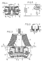
- Figures 3 and 4 also show in axial section details of variants of such a damper still established in accordance with the invention.
- Figure 5 also shows in axial section another variant of shock absorber according to the invention.
- shock absorbers considered here by way of example are intended to be interposed between the chassis of a vehicle and the internal combustion engine of this vehicle, for the purpose of supporting the engine by the chassis and damping and / or filtering the oscillations and vibrations that can be transmitted between these two sets.
- a portion of the wall of the capsule 7 is formed by a deformable flat membrane 10, the periphery of which is tightly connected to the remainder of said wall, means being provided for limiting the amplitude of the deflections of this membrane in the direction perpendicular to its mean plane to a value at most equal to 1 mm.
- the upper ring 91 advantageously came from molding with the bellows 8 and the lower ring 92 advantageously came from molding with the membrane 10.
- said membrane 10 is constituted by a circular rubber patch closing a circular hole made in the bottom of the capsule 7 coaxially with the assembly.
- the means for limiting the deflections of this membrane 10 can be, in a manner known per se, constituted by rigid grids arranged on either side of said membrane and integral with the capsule 7.
- This half cycle is followed by another half cycle in the opposite direction after the piston exceeds its neutral position corresponding to rest and so on.
- FIG. 2 reveals other provisions than those more specifically described above.
- the rigid capsule 7 is delimited by two cups flared in truncated cones and connected to each other head to tail at their large bases.
- This level is that N where the median axial zone of the disc 5 is located at rest.
- the cross section which is available for the circulation of the liquid L around this disc is maximum when the latter is in the vicinity of its rest position and decreases on the contrary when this disc deviates from said position.
- the wall of the capsule 7 could be cylindrical and hollowed out by vertically elongated grooves, the horizontal section of which would be all the greater as the point considered of the groove would be closer to the level N defined above.
- the faces of the bead 12, which are located transversely opposite the wall of the capsule 7, are given orientations substantially parallel to this wall when the piston 5 is in its rest position illustrated .
- the cross section of the constricted passage 11 is substantially the same over the entire length of this passage for said position of rest of the piston 5.
- FIG. 3 shows a variant according to which the disc 5, instead of being rigidly screwed against the end of the foot 4, would be mounted axially floating on the base of this foot.
- Rings 13 made of elastomeric material are then interposed between the facing faces of the disc 5 and its support in order to suppress the noises due to mutual shocks of the metal parts.
- These rings 13 can be attached to one and / or the other of the parts concerned and can be constituted by a portion of the bellows 8, as illustrated.
- the flat membrane 10 above is replaced by a membrane 14 in the form of an inverted pot, the bottom of which is tightly fixed to the base of the leg 4 by the screw 6 and the edge of which is extended by an outer rim 141 tightly fixed, like the edge of the previous flat membrane 10, against the edge of an opening cut in the bottom of the capsule 7: it is then this rim 141 which is extended by the ring 92 above.
- the bellows 8 can be formed by a pot completely identical to said pot 14, which leads to a symmetrical construction and greatly simplifies manufacturing.
- the auxiliary spring is no longer constituted, as in the previous embodiments, by two annular beads 91 and 92 working under compression and interposed axially between the housing 7 and 21 sheets, 22 constituting the rigid element 2, beads which may have a "stepped" profile to ensure a non-linear response of the damping as a function of the amplitudes of the oscillations to be damped.
- the housing 7 is axially separated from the two sheets 21, 22 by intervals a and b and it is connected to the rigid element 2 by an elastomer washer 93 of low stiffness working in shearing and bending.
- the beads 91 and 92 are also provided here, but they only serve to make the end-of-travel stops of the movements of the housing relative to the rigid element 2 progressive.
- the washer 93 can be interposed between the central axial zone, of maximum diameter, of the housing 7 and a facing cylindrical wall which surrounds it, forming part of the rigid element 2.
- this washer 93 has come from molding with the bellows 8 and the ring 9onge and extends these outwards, its peripheral edge being crimped between two facing pads respectively included by the two sheets 21 and 22, deformed or not, constituting the rigid element 2, possibly with the interposition of a metal ferrule 15 attached against said edge.
Landscapes
- Engineering & Computer Science (AREA)
- General Engineering & Computer Science (AREA)
- Mechanical Engineering (AREA)
- Combined Devices Of Dampers And Springs (AREA)
- Fluid-Damping Devices (AREA)
Claims (10)
- Dämpfungseinrichtung zum Einbau zwischen zwei starren Bauteilen, die aus zwei starren Elementen (1, 2) besteht, die an dem einen bzw. dem anderen Bauteil anbringbar sind, und folgende Teile enthält, die beide koaxial zueinander zwischen den beiden starren Elementen eingefügt sind: einerseits eine Hauptfederung (3) und andererseits ein Dämpfungssystem, das hintereinander einen starren Behälter (7), der mit einer viskosen Flüssigkeit (L) gefüllt ist, einen Kolben (5), der am Ende eines starren Fußstückes (4) sitzt und von der Flüssigkeit umgeben ist, und eine zusätzliche Federung (9) enthält, dadurch gekennzeichnet, daß der Behälter (7) unabhängig von der Hauptfederung (3) ist, daß die zusätzliche Federung (9) zwischen dem Behälter und dem starren Element (2) eingefügt ist, mit dem der Behälter verbunden ist, und daß das Fußstück (4) mit dem Rand einer Öffnung des Behälters, durch die es durchtritt, durch einen dichten und nachgiebigen Balg (8) verbunden ist.
- Vorrichtung nach Anspruch 1, dadurch gekennzeichnet, daß ein Abschnitt der Wandung, die den Behälter (7) begrenzt, aus einer dichten und nachgiebigen Membran (10) besteht, die mit Einrichtungen verbunden ist, die die Amplitude der vibrierenden Ausfederung seines beweglichsten Abschnittes in einer Richtung, die senkrecht zur mittleren Oberfläche dieses Abschnittes verläuft, auf einen unter 1 mm liegenden Wert begrenzt.
- Vorrichtung nach einem der vorhergehenden Ansprüche, dadurch gekennzeichnet, daß die Wandung des Behälters (7), die der gegenüberliegt, durch die das Fußstück (4) geführt ist, mit einer zweiten Öffnung versehen ist und daß der Rand dieser Öffnung mit dem Kolben (5) über einen zweiten dichten und deformierbaren Balg (14) verbunden ist.
- Vorrichtung nach Anspruch 3, dadurch gekennzeichnet, daß die beiden Bälge (8, 14) aus zwei Töpfen aus elastomerem Material bestehen, deren Böden dicht an dem Ende des Fußstückes (4) angebracht sind, das den Kolben (5) trägt, und deren Ränder durch äußere umgebogene Abschnitte verlängert sind, die ihrerseits dicht mit den Rändern der Öffnungen des Behälters verbunden sind.
- Vorrichtung nach Anspruch 4, dadurch gekennzeichnet, daß die beiden Töpfe (8, 14) aus einem Stück mit Wülsten (9₁, 9₂) durch Verformung hergestellt sind, die ringförmig ausgebildet sind und die zusätzliche Federung (9) bilden.
- Vorrichtung nach einem der vorhergehenden Ansprüche 4 und 5, dadurch gekennzeichnet, daß die beiden Töpfe (8, 14) identisch ausgebildet sind.
- Vorrichtung nach einem der vorhergehenden Ansprüche, dadurch gekennzeichnet, daß der Abschnitt der Wandung des Behälters (7), der den Kolben (5) umgibt, in dem Höhenbereich, in dem sich im Ruhezustand die mittlere axiale Zone des Kolbens befindet, vergrößert ist und sich verengt, wenn man sich von diesem Bereich auf beiden Seiten in Richtung der Schwingungen des Kolbens entfernt.
- Vorrichtung nach Anspruch 7, dadurch gekennzeichnet, daß sie als Umdrehungskörper um eine Achse ausgebildet ist und daß der Abschnitt der seitlichen ringförmigen Wandung des Behälters (7), der den Kolben umgibt, die Form von zwei Kegelstümpfen hat, die mit ihren großen Grundflächen aneinanderliegen.
- Vorrichtung nach einem der vorhergehenden Ansprüche, dadurch gekennzeichnet, daß der Kolben (5) eine Scheibe ist, die axial frei endend an dem starrem Fußstück (4) befestigt ist.
- Vorrichtung nach einem der vorhergehenden Ansprüche, dadurch gekennzeichnet, daß die zusätzliche Federung im wesentlichen aus einer Scheibe (9₃) aus elastomerem Material besteht, die auf Scherung beansprucht wird.
Applications Claiming Priority (2)
| Application Number | Priority Date | Filing Date | Title |
|---|---|---|---|
| FR8910242A FR2650355B1 (fr) | 1989-07-28 | 1989-07-28 | Perfectionnements aux dispositifs amortisseurs de vibrations |
| FR8910242 | 1989-07-28 |
Publications (2)
| Publication Number | Publication Date |
|---|---|
| EP0410896A1 EP0410896A1 (de) | 1991-01-30 |
| EP0410896B1 true EP0410896B1 (de) | 1994-04-20 |
Family
ID=9384277
Family Applications (1)
| Application Number | Title | Priority Date | Filing Date |
|---|---|---|---|
| EP90402175A Expired - Lifetime EP0410896B1 (de) | 1989-07-28 | 1990-07-27 | Verbesserungen an hydraulischen Schwingungsdämpfern |
Country Status (5)
| Country | Link |
|---|---|
| US (1) | US5127636A (de) |
| EP (1) | EP0410896B1 (de) |
| DE (1) | DE69008264T2 (de) |
| ES (1) | ES2051485T3 (de) |
| FR (1) | FR2650355B1 (de) |
Cited By (2)
| Publication number | Priority date | Publication date | Assignee | Title |
|---|---|---|---|---|
| US7341244B1 (en) | 2007-02-26 | 2008-03-11 | Paulstra Crc | Hydraulic antivibration support |
| DE102018217688A1 (de) * | 2018-10-16 | 2020-04-16 | Audi Ag | Hydraulisch dämpfendes Lager für ein Kraftfahrzeug |
Families Citing this family (22)
| Publication number | Priority date | Publication date | Assignee | Title |
|---|---|---|---|---|
| FR2675871B1 (fr) * | 1991-04-29 | 1995-02-17 | Hutchinson | Perfectionnements apportes aux dispositifs antivibratoires hydrauliques. |
| DE4131771A1 (de) * | 1991-09-24 | 1993-04-01 | Metzeler Gimetall Ag | Elastisches motorlager |
| DE4139046A1 (de) * | 1991-11-27 | 1993-06-03 | Metzeler Gimetall Ag | Elastisches motorlager |
| WO1995007419A1 (fr) * | 1993-09-08 | 1995-03-16 | Kabushiki Kaisha Komatsu Seisakusho | Support caoutchouc etanche au liquide |
| US5464196A (en) * | 1994-04-20 | 1995-11-07 | Fabreeka International, Inc. | Vibration isolator |
| US5927698A (en) * | 1996-07-24 | 1999-07-27 | Toyoda Gosei Co., Ltd. | Liquid sealed-type vibration insulating device |
| GB2316731B (en) * | 1996-07-29 | 2000-09-27 | Draftex Ind Ltd | Vibration damping assemblies |
| GB2317433B (en) * | 1996-09-24 | 2000-09-06 | Draftex Ind Ltd | Vibration damping assemblies |
| KR100216425B1 (ko) * | 1997-07-16 | 1999-08-16 | 정몽규 | 롤링 제한용 마운트의 구조 |
| US6378851B1 (en) | 2000-10-25 | 2002-04-30 | Lord Corporation | Fluid and elastomer apparatus with discrete volume compensator and secondary compliance |
| JP4270502B2 (ja) * | 2004-02-13 | 2009-06-03 | 東海ゴム工業株式会社 | エンジンマウント |
| US7055811B2 (en) * | 2004-05-03 | 2006-06-06 | Toyo Tire And Rubber Co., Ltd. | Vibration isolating device |
| US20080296816A1 (en) * | 2004-10-29 | 2008-12-04 | Fukoku Co., Ltd | Vibration-Isolating Support Device |
| US20090014930A1 (en) * | 2005-11-15 | 2009-01-15 | Fukoku Co., Ltd | Liquid sealed mount and method of assembling the same |
| KR100832361B1 (ko) * | 2006-11-22 | 2008-05-26 | (주)디티알 | 이중 절연 유체봉입식 엔진 마운트 |
| US7552916B1 (en) * | 2007-04-27 | 2009-06-30 | Cadillac Rubber & Plastics, Inc. | Hydraulically damped mounting device |
| CN101839301A (zh) * | 2010-05-27 | 2010-09-22 | 宁波奥赛减震系统有限公司 | 减震悬置 |
| DE102016203116A1 (de) * | 2016-02-26 | 2017-08-31 | Deckel Maho Pfronten Gmbh | Bearbeitungseinheit für eine Werkzeugmaschine und Werkzeugmaschine mit einer derartigen Bearbeitungseinheit |
| CN107775367B (zh) * | 2016-08-26 | 2024-06-07 | 中石化石油工程技术服务有限公司 | 一种浮箱式管具维修支撑架 |
| US10442469B2 (en) | 2017-08-03 | 2019-10-15 | The Pullman Company | Hydraulic body mount with compressible bumper |
| US10300953B2 (en) | 2017-08-03 | 2019-05-28 | The Pullman Company | Hydraulic body mount |
| CN113513558B (zh) * | 2021-07-07 | 2022-11-11 | 深圳市朝上科技有限责任公司 | 一种基于混合阻尼模式的高输出力隔振悬置 |
Family Cites Families (16)
| Publication number | Priority date | Publication date | Assignee | Title |
|---|---|---|---|---|
| US2380899A (en) * | 1944-01-21 | 1945-07-31 | Lord Mfg Co | Mounting |
| US3368807A (en) * | 1966-01-19 | 1968-02-13 | Litton Systems Inc | Vibration isolator |
| ES421635A1 (es) * | 1972-12-21 | 1976-07-16 | Arfina Anstalt Finanz | Dispositivo aislador de vibraciones. |
| DE2503581A1 (de) * | 1975-01-29 | 1976-08-05 | Kaspar Lochner | Vorrichtung zum daempfen von mechanischen sowie zum unterdruecken von akustischen schwingungen |
| IT1165137B (it) * | 1979-06-29 | 1987-04-22 | Gomma Antivibranti Applic | Sopporto ammortizzante per la sospensione di un corpo oscillante ad una struttura di sopporto,particolarmente per la sospensione del motore al telaio di un autoveicolo |
| DE3005983A1 (de) * | 1980-02-18 | 1981-08-20 | Fa. Carl Freudenberg, 6940 Weinheim | Gedaempftes federelement zur schwingungsisolierung |
| IT1131678B (it) * | 1980-07-04 | 1986-06-25 | Gomma Antivibranti Applic | Sopporto ammortizzante per la sospensione di un corpo oscillante ad una struttura di sopporto |
| IT1161640B (it) * | 1983-03-11 | 1987-03-18 | Pirelli | Unita' di sopporto atta a sopportare elasticamente una massa e a smorzarne le vibrazioni |
| FR2549558B1 (fr) * | 1983-07-21 | 1987-12-18 | Hutchinson | Dispositif amortisseur de vibrations |
| DE3330462C2 (de) * | 1983-08-24 | 1986-11-06 | Fa. Carl Freudenberg, 6940 Weinheim | Hydraulisch bedämpftes Motorlager |
| FR2563879B1 (fr) * | 1984-05-04 | 1988-08-26 | Hutchinson Sa | Support antivibratoire hydraulique |
| FR2577641B1 (fr) * | 1985-02-15 | 1989-05-05 | Hutchinson | Perfectionnements aux supports antivibratoires hydrauliques |
| JPS636248U (de) * | 1986-06-30 | 1988-01-16 | ||
| GB8619240D0 (en) * | 1986-08-06 | 1986-09-17 | Dunlop Ltd | Elastomeric mounting |
| DE8717411U1 (de) * | 1987-09-18 | 1988-09-15 | Metzeler GmbH, 8000 München | Elastisches Lager, insbesondere Motorlager für Kraftfahrzeuge |
| DE3808996A1 (de) * | 1988-03-17 | 1989-09-28 | Metzeler Gmbh | Hydraulisch daempfendes zweikammer - motorlager |
-
1989
- 1989-07-28 FR FR8910242A patent/FR2650355B1/fr not_active Expired - Fee Related
-
1990
- 1990-07-27 EP EP90402175A patent/EP0410896B1/de not_active Expired - Lifetime
- 1990-07-27 ES ES90402175T patent/ES2051485T3/es not_active Expired - Lifetime
- 1990-07-27 DE DE69008264T patent/DE69008264T2/de not_active Expired - Fee Related
- 1990-07-27 US US07/558,499 patent/US5127636A/en not_active Expired - Fee Related
Cited By (3)
| Publication number | Priority date | Publication date | Assignee | Title |
|---|---|---|---|---|
| US7341244B1 (en) | 2007-02-26 | 2008-03-11 | Paulstra Crc | Hydraulic antivibration support |
| DE102018217688A1 (de) * | 2018-10-16 | 2020-04-16 | Audi Ag | Hydraulisch dämpfendes Lager für ein Kraftfahrzeug |
| DE102018217688B4 (de) | 2018-10-16 | 2022-04-28 | Audi Ag | Hydraulisch dämpfendes Lager für ein Kraftfahrzeug |
Also Published As
| Publication number | Publication date |
|---|---|
| DE69008264T2 (de) | 1994-11-17 |
| DE69008264D1 (de) | 1994-05-26 |
| FR2650355A1 (fr) | 1991-02-01 |
| FR2650355B1 (fr) | 1994-01-28 |
| US5127636A (en) | 1992-07-07 |
| ES2051485T3 (es) | 1994-06-16 |
| EP0410896A1 (de) | 1991-01-30 |
Similar Documents
| Publication | Publication Date | Title |
|---|---|---|
| EP0410896B1 (de) | Verbesserungen an hydraulischen Schwingungsdämpfern | |
| EP0596787B1 (de) | Verbesserungen für hydraulische Antivibrationslagen | |
| EP0352184B1 (de) | Obere Gelenkverbindung zwischen einer Feder-Dämpfer-Einheit und dem Rahmen eines Kraftfahrzeugs | |
| EP0409707B1 (de) | Hydraulische Antischwingungsvorrichtungen | |
| FR2559864A1 (fr) | Isolateur de vibrations | |
| EP1301733B1 (de) | Hubbegrenzung für einen stossdämpfer eines kraftfahrzeuges und herstellverfahren dafür | |
| FR2492026A1 (fr) | Dispositif porteur en caoutchouc possedant une capacite d'amortissement pneumatique | |
| FR2755489A1 (fr) | Support antivibratoire hydraulique | |
| EP1176336A1 (de) | Hydraulisches, schwingungsdämpfendes Lager und Kraftfahrzeug, welches mit einem solchen Lager ausgerüstet ist | |
| FR2476782A1 (fr) | Amortisseur pour suspension de vehicule automobile | |
| EP0088682A1 (de) | Hydraulischer Membrandämpfer | |
| FR2922617A1 (fr) | Appui pour un ressort helicoidal de compression | |
| FR2828540A1 (fr) | Support antivibratoire hydraulique | |
| FR2812362A1 (fr) | Support antivibratoire hydraulique et son procede de fabrication | |
| EP0461024B1 (de) | Hydraulische Antischwingungslager | |
| EP0225227B1 (de) | Änderungen an hydraulischen Anti-Schwingungslagern | |
| FR2627545A1 (fr) | Coussinet isolant du bruit de structure, en particulier coussinet pour moteurs a combustion interne | |
| EP2282076B1 (de) | Schwingungsdämpfervorrichtung für ein Fahrzeug, und eine solche Vorrichtung umfassendes Fahrzeug | |
| EP0305246B1 (de) | Hydraulisch gedämpfte Lager | |
| EP0894995B1 (de) | Schwingungsdämpfendes Lager | |
| FR2628805A1 (fr) | Structure de montage elastique a remplissage de fluide a elements mobiles et a orifices | |
| FR2851312A1 (fr) | Support antivibratoire hydraulique | |
| EP0511907A1 (de) | Verbesserungen an hydraulischer Antischwingungsvorrichtungen | |
| EP0656486B1 (de) | Verbesserungen an hydraulischen Schwingungsdämpfern | |
| FR2635155A1 (fr) | Perfectionnements aux supports elastiques comportant des moyens de butee |
Legal Events
| Date | Code | Title | Description |
|---|---|---|---|
| PUAI | Public reference made under article 153(3) epc to a published international application that has entered the european phase |
Free format text: ORIGINAL CODE: 0009012 |
|
| AK | Designated contracting states |
Kind code of ref document: A1 Designated state(s): BE DE ES FR GB IT LU NL SE |
|
| 17P | Request for examination filed |
Effective date: 19910419 |
|
| 17Q | First examination report despatched |
Effective date: 19930312 |
|
| GRAA | (expected) grant |
Free format text: ORIGINAL CODE: 0009210 |
|
| AK | Designated contracting states |
Kind code of ref document: B1 Designated state(s): BE DE ES FR GB IT LU NL SE |
|
| PG25 | Lapsed in a contracting state [announced via postgrant information from national office to epo] |
Ref country code: IT Free format text: LAPSE BECAUSE OF FAILURE TO SUBMIT A TRANSLATION OF THE DESCRIPTION OR TO PAY THE FEE WITHIN THE PRE;WARNING: LAPSES OF ITALIAN PATENTS WITH EFFECTIVE DATE BEFORE 2007 MAY HAVE OCCURRED AT ANY TIME BEFORE 2007. THE CORRECT EFFECTIVE DATE MAY BE DIFFERENT FROM THE ONE RECORDED.SCRIBED TIME-LIMIT Effective date: 19940420 Ref country code: SE Free format text: THE PATENT HAS BEEN ANNULLED BY A DECISION OF A NATIONAL AUTHORITY Effective date: 19940420 Ref country code: NL Effective date: 19940420 |
|
| GBT | Gb: translation of ep patent filed (gb section 77(6)(a)/1977) |
Effective date: 19940420 |
|
| REF | Corresponds to: |
Ref document number: 69008264 Country of ref document: DE Date of ref document: 19940526 |
|
| REG | Reference to a national code |
Ref country code: ES Ref legal event code: FG2A Ref document number: 2051485 Country of ref document: ES Kind code of ref document: T3 |
|
| PG25 | Lapsed in a contracting state [announced via postgrant information from national office to epo] |
Ref country code: BE Effective date: 19940731 Ref country code: LU Free format text: LAPSE BECAUSE OF NON-PAYMENT OF DUE FEES Effective date: 19940731 |
|
| NLV1 | Nl: lapsed or annulled due to failure to fulfill the requirements of art. 29p and 29m of the patents act | ||
| PLBI | Opposition filed |
Free format text: ORIGINAL CODE: 0009260 |
|
| BERE | Be: lapsed |
Owner name: PAULSTRA G.M.B.H. Effective date: 19940731 |
|
| 26 | Opposition filed |
Opponent name: METZELER GIMETALL AG Effective date: 19950119 |
|
| PLBQ | Unpublished change to opponent data |
Free format text: ORIGINAL CODE: EPIDOS OPPO |
|
| PLAB | Opposition data, opponent's data or that of the opponent's representative modified |
Free format text: ORIGINAL CODE: 0009299OPPO |
|
| R26 | Opposition filed (corrected) |
Opponent name: METZELER GIMETALL AG Effective date: 19950119 |
|
| PLBL | Opposition procedure terminated |
Free format text: ORIGINAL CODE: EPIDOS OPPC |
|
| PLBM | Termination of opposition procedure: date of legal effect published |
Free format text: ORIGINAL CODE: 0009276 |
|
| STAA | Information on the status of an ep patent application or granted ep patent |
Free format text: STATUS: OPPOSITION PROCEDURE CLOSED |
|
| 27C | Opposition proceedings terminated |
Effective date: 19970316 |
|
| PGFP | Annual fee paid to national office [announced via postgrant information from national office to epo] |
Ref country code: ES Payment date: 19990701 Year of fee payment: 10 |
|
| PGFP | Annual fee paid to national office [announced via postgrant information from national office to epo] |
Ref country code: DE Payment date: 19990715 Year of fee payment: 10 |
|
| PGFP | Annual fee paid to national office [announced via postgrant information from national office to epo] |
Ref country code: GB Payment date: 19990720 Year of fee payment: 10 |
|
| PGFP | Annual fee paid to national office [announced via postgrant information from national office to epo] |
Ref country code: FR Payment date: 19990726 Year of fee payment: 10 |
|
| PG25 | Lapsed in a contracting state [announced via postgrant information from national office to epo] |
Ref country code: GB Free format text: LAPSE BECAUSE OF NON-PAYMENT OF DUE FEES Effective date: 20000727 |
|
| PG25 | Lapsed in a contracting state [announced via postgrant information from national office to epo] |
Ref country code: ES Free format text: LAPSE BECAUSE OF NON-PAYMENT OF DUE FEES Effective date: 20000728 |
|
| PG25 | Lapsed in a contracting state [announced via postgrant information from national office to epo] |
Ref country code: DE Free format text: LAPSE BECAUSE OF NON-PAYMENT OF DUE FEES Effective date: 20000731 |
|
| GBPC | Gb: european patent ceased through non-payment of renewal fee |
Effective date: 20000727 |
|
| PG25 | Lapsed in a contracting state [announced via postgrant information from national office to epo] |
Ref country code: FR Free format text: LAPSE BECAUSE OF NON-PAYMENT OF DUE FEES Effective date: 20010330 |
|
| REG | Reference to a national code |
Ref country code: FR Ref legal event code: ST |
|
| REG | Reference to a national code |
Ref country code: ES Ref legal event code: FD2A Effective date: 20010810 |