EP0410771A2 - Appareil de traitement d'image - Google Patents
Appareil de traitement d'image Download PDFInfo
- Publication number
- EP0410771A2 EP0410771A2 EP90308235A EP90308235A EP0410771A2 EP 0410771 A2 EP0410771 A2 EP 0410771A2 EP 90308235 A EP90308235 A EP 90308235A EP 90308235 A EP90308235 A EP 90308235A EP 0410771 A2 EP0410771 A2 EP 0410771A2
- Authority
- EP
- European Patent Office
- Prior art keywords
- image
- desired range
- memory area
- image data
- image information
- Prior art date
- Legal status (The legal status is an assumption and is not a legal conclusion. Google has not performed a legal analysis and makes no representation as to the accuracy of the status listed.)
- Withdrawn
Links
Images

Classifications
-
- G—PHYSICS
- G06—COMPUTING; CALCULATING OR COUNTING
- G06F—ELECTRIC DIGITAL DATA PROCESSING
- G06F17/00—Digital computing or data processing equipment or methods, specially adapted for specific functions
-
- H—ELECTRICITY
- H04—ELECTRIC COMMUNICATION TECHNIQUE
- H04N—PICTORIAL COMMUNICATION, e.g. TELEVISION
- H04N1/00—Scanning, transmission or reproduction of documents or the like, e.g. facsimile transmission; Details thereof
- H04N1/387—Composing, repositioning or otherwise geometrically modifying originals
- H04N1/3872—Repositioning or masking
- H04N1/3873—Repositioning or masking defined only by a limited number of coordinate points or parameters, e.g. corners, centre; for trimming
- H04N1/3875—Repositioning or masking defined only by a limited number of coordinate points or parameters, e.g. corners, centre; for trimming combined with enlarging or reducing
Definitions
- the present invention relates generally to an image data processing apparatus, and more particularly, to an image data processing apparatus such as a document image filing apparatus.
- a document image filing apparatus which reads image data, such as documents created in large quantities through two-dimensional scanning by a two-dimensional scanner, stores this read image data on an optical disc, retrieves and reads optional stored image data, and outputs them in a visible state through an output device, for instance, a CRT (Cathode Ray Tube) display device or a printer using an interface.
- image data such as documents created in large quantities through two-dimensional scanning by a two-dimensional scanner
- image data of one of the documents is read with a scanner and stored in a page memory which is an image memory, and is displayed on a CRT display device.
- Image data of the other document is read with the scanner, stored in the other region of the image memory, and is displayed on the CRT display device.
- a designation is given to reduce the image of the other document at a desired reduction rate, and after executing the reduction process accordingly, the image stored in the region is updated to the reduced size and displayed on the CRT display device. Thereafter, a superimposition with the image of another document is designated.
- the reduced image stored in the other region is stored in the designated position in the first region according to the designation and then displayed on the CRT display device.
- the present invention therefore seeks to provide an image data processing apparatus which assures efficient image editing operation.
- the present invention also seeks to provide an image data processing apparatus which is able to reduce the size of image memory areas to be used and makes efficient use of image memory.
- An image data processing apparatus includes a scanner for individually reading first and second image information from first and second documents, a page memory for storing the first image information into its first memory area, a display device for displaying a first image corresponding to the first image information stored in the first memory area of the page memory, a keyboard or a mouse for defining a desired range to be substituted with a second image corresponding to the second image information, in the first image displayed on the display device, a CPU for determining a magnifying ratio of the second image suited to the desired range, according to the sizes of the desired range and the second image, an enlargement/reduction circuit for magnifying the second image in response to the magnifying ratio determined by the CPU and the CPU for further processing a storage of the second image information read by the scanner into a second memory area corresponding to the desired range in the first memory area, according to the magnifying ratio.
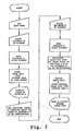
- FIGURE 1 the general construction of the image data processing apparatus will briefly explained before a detailed description of the present invention is presented.
- FIGURE 1 is a block diagram showing general construction of the image data processing apparatus.
- the image data processing apparatus comprises a control module 10, a memory module 12, an image processing module 14, a communication control module 16, a scanner 18, an optical disc 20 and an optical disc device 22, a aboard 23, a CRT display device 24, a printer 25, a magnetic disc 26, a magnetic disc device 27, a mouse 29, a system bus 30 and an image data bus 32.
- the control module 10 comprises a CPU (Central Processing Unit) 34 which performs various processes such as storage, retrieval and editing of image data, etc. and the interface circuit 36 which connects the optical disc device 22 and the magnetic disc device 27 to the CPU 34.
- CPU Central Processing Unit
- the keyboard 23 and the mouse 29 are connected to the CPU 34.
- the keyboard, mouse, and CPU together form a means for defining the size and orientation of image data to be displayed.
- the interface circuit 36 includes a DMA (Direct Memory Access) channel and its associated circuits and transfers data at high speed between the optical disc device 22 or the magnetic disc device 27 and memories in the memory module 12, the image processing module 14 or the communication control module without involving the CPU 34.
- DMA Direct Memory Access
- the memory module 12 comprises a main memory 38 which stores various processing programs (which perform operations such as storage, retrieval, editing, etc. of image data and control data, etc.), a page memory 40 (which is an image memory having a storage capacity corresponding to image data of several pages of A4 standard size document) which acts as a storage means to store the page image data, the display memory 42 as a display interface, and the display control device 44.
- various processing programs which perform operations such as storage, retrieval, editing, etc. of image data and control data, etc.
- a page memory 40 which is an image memory having a storage capacity corresponding to image data of several pages of A4 standard size document which acts as a storage means to store the page image data
- the display memory 42 as a display interface
- the display control device 44 the display control device 44.
- the page memory 40 is a memory for temporarily storing, for instance, image data to be stored in or read out of the optical disc 20.
- image data to be displayed in the display window (not shown) which is formed in the CRT display device 24, that is, magnified to enlarge or reduce, rotated, superimposed or reversed black and white image data of the page memory 40, are stored.
- the display control device 44 controls the display process of the CRT display device 24.
- the image processing module 14 comprises the enlargement/reduction circuit 46 which performs enlargement/reduction of image data, the length and breadth conversion circuit 48 which performs a rotating of the image data by length and breadth conversion of the image data, the compression/expansion circuit (CODEC) 50 which performs the encode process by compressing (reduce redundancy) and expanding (restore the reduced redundancy), the scanner interface 52 for the scanner 18, the printer interface 54 for the printer 25 and the internal bus 56 which connects the enlargement/reduction circuit 46 and the length and breadth conversion circuit 48, the compression/expansion circuit 50, the scanner interface 52 and the printer interface 54.
- CDEC compression/expansion circuit
- the communication control module 16 comprises the communication interface 58, which supplies retrieval data transmitted through the communication line to the main memory 38 and transmits the image data corresponding to the received retrieval data. Further, it supplies image data to be stored in the optical disc 20 to the page memory 40 and, at the same time, supplies retrieval data corresponding to the image data to the main memory 38.
- the details of the communication interface 58 will be described later.
- the system bus 30 is the bus for transmitting/receiving control data among the modules and connects the control module 10, the memory module 12, the image process module 14 and the communication control module 16.
- the image data bus 32 is the bus for transmitting/receiving image data and connects the memory module 12, the image process module 14 and the communication control module 16.
- the scanner 18 is, for instance, a two-dimensional scanner which generates electric signals corresponding to image data on a document by scanning the surface of the document two-dimensionally with laser beam light. This scanner functions as a reading means for reading an image formed on a document.
- the optical disc device 22 stores image data read by the scanner 18 in the optical disc 20 successively and retrieves image data corresponding to retrieval data designated by the keyboard 23, etc., from the optical disc 20.
- the keyboard 23 is used to input peculiar retrieval data corresponding to image data to be stored in the optical disc 20 and various operating commands such as storage, retrieval, edit process, etc. Further, the mouse 29 is used to select or direct the display content at the position where the cursor is positioned (for example, various operation modes, defining of range for edited image or icon) by giving an instruction at a desired position by moving the cursor (not shown) being displayed on the display window of the CRT display device 24 in the vertical and horizontal directions.
- the CRT display device (Cathode Ray Tube display device) 24 operates to display image data read by the scanner 18 or retrieved from the optical disc 20.
- This CRT display device 24 is a multi-window type display device which has, e.g., four windows (not shown) formed in the display area so that four different sets of image data can be displayed simultaneously. Each set of the image data displayed on each window can be enlarged, reduced, rotated or scrolled independently.
- the printer 25 is to print and output (hard copy) image data read through the scanner 18, retrieved from the optical disc 20, or displayed on the CRT display device 24.
- the magnetic disc device 27 stores various process programs in the magnetic disc 28 which is loaded on this magnetic disc device 27 and further, stores retrieval data composed of retrieval data input from the keyboard 23 and storage address, image size, etc. on the optical disc 20 in which image data corresponding to the retrieval data is stored.
- the edit mode is selected and set through the keyboard 23 for two documents A and B that are read by the scanner 18, and placing the document A on the scanner 18, it is directed to read the image of the document A through the keyboard 23.
- the scanner 18 is then operated by the CPU 34, the scanner 18 scans the image of this set document A two-dimensionally and photoelectrically converts it into image data.
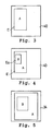
- This photoelectrically converted image line data is stored successively in the storage area E in the page memory 40 shown in FIGURE 3.
- the A4 standard size space is secured for the storage area E in the page memory 40 corresponding to the size of the document A that is read by the scanner 18.
- the image of the document A stored in the storage area E of the page memory 40 is stored in the display memory 42 and displayed on the CRT display device 24.
- the desired superimposing position, superimposing range, and rotating angle of the image of the document B are set up by tracing the image being displayed on the CRT display device 24 using the mouse 29.
- the CPU 34 operates the scanner 18 to scan the image of the set document B two-dimensionally and photoelectrically convert the image into image data. In this case, the CPU 34 calculates a reduction rate of the image based on the defined superimposing range of the image of the document B and its image size read by the scanner 18.
- the line data of the image photoelectrically converted by the scanner 18 is reduced at the reduction rate through the enlargement/reduction circuit 46, and stored in order in a selected area Ea in the storage area E of the page memory 40, shown in FIGURE 4.
- the selected area Ea is determined according to the superimposing position and the superimposing range defined by the mouse 29.
- the image of the document A and the reduced image of the document B which have been superimposed and stored in the storage area E of the page memory 40 are then stored in the display memory 42 and displayed on the CRT display device 24 as shown in FIGURE 5.
- the images reduced through the enlargement/reduction circuit 46 are rotated using the length and breadth conversion circuit 48 and then are stored in order in the selected area Ea in the storage area E of the page memory 40.
- the number of image edit processes involved in combining the reduced image of document B into the image of document A is reduced and it is therefore possible to promote efficiency of the image editing operation and reduce its time consumption.
- 2 areas in A4 standard size had been needed in the image memory in the past, but now, only one A4 standard size area is required in the image memory.
- the image memory can be used for other applications, for instance, for storage of character data, proceeding images, etc. or as a memory for CPU. As a result, the areas of the image memory used in editing is reduced and the image memory can be efficiently used.
- two images can be edited even when one of the image sizes is the same as the storage capacity of the image memory.
- the present invention it is possible to provide an image data processing apparatus which increases the efficiency of the image editing operation and reduces its time consumption, and also assures efficient use of the image memory.
- the present invention can provide an extremely preferable image data processing apparatus.
Landscapes
- Engineering & Computer Science (AREA)
- Multimedia (AREA)
- Signal Processing (AREA)
- Physics & Mathematics (AREA)
- Theoretical Computer Science (AREA)
- Mathematical Physics (AREA)
- Databases & Information Systems (AREA)
- Software Systems (AREA)
- General Engineering & Computer Science (AREA)
- General Physics & Mathematics (AREA)
- Data Mining & Analysis (AREA)
- Processing Or Creating Images (AREA)
- Editing Of Facsimile Originals (AREA)
- Information Retrieval, Db Structures And Fs Structures Therefor (AREA)
- Image Processing (AREA)
Applications Claiming Priority (2)
| Application Number | Priority Date | Filing Date | Title |
|---|---|---|---|
| JP1195689A JPH0359778A (ja) | 1989-07-28 | 1989-07-28 | 画像処理装置 |
| JP195689/89 | 1989-07-28 |
Publications (2)
| Publication Number | Publication Date |
|---|---|
| EP0410771A2 true EP0410771A2 (fr) | 1991-01-30 |
| EP0410771A3 EP0410771A3 (en) | 1992-09-23 |
Family
ID=16345360
Family Applications (1)
| Application Number | Title | Priority Date | Filing Date |
|---|---|---|---|
| EP19900308235 Withdrawn EP0410771A3 (en) | 1989-07-28 | 1990-07-26 | Image processing apparatus |
Country Status (4)
| Country | Link |
|---|---|
| US (1) | US5195174A (fr) |
| EP (1) | EP0410771A3 (fr) |
| JP (1) | JPH0359778A (fr) |
| KR (1) | KR930004440B1 (fr) |
Cited By (1)
| Publication number | Priority date | Publication date | Assignee | Title |
|---|---|---|---|---|
| WO1992020033A1 (fr) * | 1991-04-24 | 1992-11-12 | Michael Sussman | Dispositif numerique pour l'agrandissement des documents |
Families Citing this family (15)
| Publication number | Priority date | Publication date | Assignee | Title |
|---|---|---|---|---|
| US5271065A (en) * | 1990-09-28 | 1993-12-14 | Xerox Corporation | Electronic printing system for printing signatures |
| JP3251959B2 (ja) * | 1991-10-17 | 2002-01-28 | 株式会社リコー | 画像形成装置 |
| US5420965A (en) * | 1992-06-05 | 1995-05-30 | Software Projects, Inc. | Single pass method of compressing data transmitted to command driven terminal |
| JPH06191093A (ja) * | 1992-12-25 | 1994-07-12 | Fuji Xerox Co Ltd | 記録装置 |
| JP3305454B2 (ja) * | 1993-10-01 | 2002-07-22 | キヤノン株式会社 | 画像形成システム |
| US5767855A (en) * | 1997-05-19 | 1998-06-16 | International Business Machines Corporation | Selectively enlarged viewer interactive three-dimensional objects in environmentally related virtual three-dimensional workspace displays |
| JP3962454B2 (ja) * | 1997-09-08 | 2007-08-22 | キヤノン株式会社 | 画像処理装置及び方法 |
| US7382927B2 (en) * | 1999-01-08 | 2008-06-03 | Sharp Laboratories Of America, Inc. | System for constructing mosaic images |
| JP2001186334A (ja) * | 1999-12-27 | 2001-07-06 | Canon Inc | 画像処理装置、画像処理システム、画像処理方法、及び記憶媒体 |
| US6774912B1 (en) | 2000-03-16 | 2004-08-10 | Matrox Graphics Inc. | Multiple display device display controller with video overlay and full screen video outputs |
| US7400333B1 (en) | 2000-03-16 | 2008-07-15 | Matrox Graphics Inc. | Video display system with two controllers each able to scale and blend RGB and YUV surfaces |
| JP4398474B2 (ja) * | 2004-12-28 | 2010-01-13 | 富士通株式会社 | 画像内の処理対象の位置を特定する画像処理装置 |
| KR100777462B1 (ko) * | 2005-01-19 | 2007-11-21 | 삼성전자주식회사 | 스캐닝장치, 그것을 구비하는 스캐닝시스템 및 스캐닝방법 |
| JP2007013607A (ja) * | 2005-06-30 | 2007-01-18 | Canon Inc | 画像処理装置、画像処理装置の制御方法、プログラム及び記憶媒体 |
| JP5532992B2 (ja) * | 2010-02-10 | 2014-06-25 | セイコーエプソン株式会社 | 書画カメラ、書画カメラの制御方法およびプログラム |
Citations (3)
| Publication number | Priority date | Publication date | Assignee | Title |
|---|---|---|---|---|
| JPS6019355A (ja) * | 1983-07-13 | 1985-01-31 | Fujitsu Ltd | 文書作成装置 |
| JPS6370666A (ja) * | 1986-09-12 | 1988-03-30 | Nippon Telegr & Teleph Corp <Ntt> | 画像貼り合わせ装置 |
| JPS63272267A (ja) * | 1987-04-30 | 1988-11-09 | Toshiba Corp | 情報処理装置 |
Family Cites Families (1)
| Publication number | Priority date | Publication date | Assignee | Title |
|---|---|---|---|---|
| JPS61275795A (ja) * | 1985-05-31 | 1986-12-05 | キヤノン株式会社 | 文書処理装置 |
-
1989
- 1989-07-28 JP JP1195689A patent/JPH0359778A/ja active Pending
-
1990
- 1990-07-25 US US07/557,001 patent/US5195174A/en not_active Expired - Fee Related
- 1990-07-26 EP EP19900308235 patent/EP0410771A3/en not_active Withdrawn
- 1990-07-27 KR KR1019900011606A patent/KR930004440B1/ko active IP Right Grant
Patent Citations (3)
| Publication number | Priority date | Publication date | Assignee | Title |
|---|---|---|---|---|
| JPS6019355A (ja) * | 1983-07-13 | 1985-01-31 | Fujitsu Ltd | 文書作成装置 |
| JPS6370666A (ja) * | 1986-09-12 | 1988-03-30 | Nippon Telegr & Teleph Corp <Ntt> | 画像貼り合わせ装置 |
| JPS63272267A (ja) * | 1987-04-30 | 1988-11-09 | Toshiba Corp | 情報処理装置 |
Non-Patent Citations (3)
| Title |
|---|
| PATENT ABSTRACTS OF JAPAN vol. 12, no. 304 (E-646)(3151) 18 August 1988 & JP-A-63 070 666 ( NIPPON TELEGR & TELEPH CORP ) 30 March 1988 * |
| PATENT ABSTRACTS OF JAPAN vol. 13, no. 99 (E-724)(3447) 8 March 1989 & JP-A-63 272 267 ( TOSHIBA CORP ) 9 November 1988 * |
| PATENT ABSTRACTS OF JAPAN vol. 9, no. 136 (E-320)(1859) 12 June 1985 & JP-A-60 019 355 ( FUJITSU K.K. ) 31 January 1985 * |
Cited By (3)
| Publication number | Priority date | Publication date | Assignee | Title |
|---|---|---|---|---|
| WO1992020033A1 (fr) * | 1991-04-24 | 1992-11-12 | Michael Sussman | Dispositif numerique pour l'agrandissement des documents |
| AU656401B2 (en) * | 1991-04-24 | 1995-02-02 | Michael Sussman | Digital document magnifier |
| US5586196A (en) * | 1991-04-24 | 1996-12-17 | Michael Sussman | Digital document magnifier |
Also Published As
| Publication number | Publication date |
|---|---|
| EP0410771A3 (en) | 1992-09-23 |
| KR910003520A (ko) | 1991-02-27 |
| JPH0359778A (ja) | 1991-03-14 |
| US5195174A (en) | 1993-03-16 |
| KR930004440B1 (ko) | 1993-05-27 |
Similar Documents
| Publication | Publication Date | Title |
|---|---|---|
| US4893258A (en) | Data processing apparatus having enlargement/reduction functions capable of setting different magnification in different directions | |
| US5119081A (en) | Control apparatus of image filing system | |
| US5195174A (en) | Image data processing apparatus capable of composing one image from a plurality of images | |
| JPH0212570A (ja) | 画像処理装置 | |
| JPH04344524A (ja) | 画像表示装置 | |
| EP0533177B1 (fr) | Méthode de détection et d'élimination de bruit | |
| US5199102A (en) | Image processing apparatus having multiple display areas for editing | |
| US5499110A (en) | Image processing apparatus for synthesizing different input data without using hard copy | |
| US5357601A (en) | Apparatus for processing superimposed image information by designating sizes of superimposed and superimposing images | |
| JPS6084590A (ja) | 画像処理システム | |
| JPH0512396A (ja) | 画像情報処理装置 | |
| US5583955A (en) | Image processing apparatus | |
| JP2559710B2 (ja) | 画像処理方法 | |
| JP3064305B2 (ja) | ディジタル複写機 | |
| JP2513636B2 (ja) | 画像処理装置 | |
| JP2721154B2 (ja) | 画像処理装置 | |
| JP2641432B2 (ja) | インタフエース装置 | |
| JP2945028B2 (ja) | 画像処理指定領域情報計算装置 | |
| JPH0581397A (ja) | ページスクロール方法及び画像処理装置 | |
| JPH04342076A (ja) | 画像情報処理装置 | |
| JPH04342363A (ja) | 画像情報処理装置 | |
| JPH02171919A (ja) | 画像処理装置 | |
| JPH0362265A (ja) | 画像処理装置 | |
| JPH02260028A (ja) | 画像処理装置 | |
| JPH02260030A (ja) | 画像処理装置 |
Legal Events
| Date | Code | Title | Description |
|---|---|---|---|
| PUAI | Public reference made under article 153(3) epc to a published international application that has entered the european phase |
Free format text: ORIGINAL CODE: 0009012 |
|
| 17P | Request for examination filed |
Effective date: 19900821 |
|
| AK | Designated contracting states |
Kind code of ref document: A2 Designated state(s): DE FR GB |
|
| PUAL | Search report despatched |
Free format text: ORIGINAL CODE: 0009013 |
|
| AK | Designated contracting states |
Kind code of ref document: A3 Designated state(s): DE FR GB |
|
| STAA | Information on the status of an ep patent application or granted ep patent |
Free format text: STATUS: THE APPLICATION HAS BEEN WITHDRAWN |
|
| 18W | Application withdrawn |
Withdrawal date: 19930518 |