EP0410073B1 - Device for transporting mushrooms in mushroom growing rooms - Google Patents
Device for transporting mushrooms in mushroom growing rooms Download PDFInfo
- Publication number
- EP0410073B1 EP0410073B1 EP90102527A EP90102527A EP0410073B1 EP 0410073 B1 EP0410073 B1 EP 0410073B1 EP 90102527 A EP90102527 A EP 90102527A EP 90102527 A EP90102527 A EP 90102527A EP 0410073 B1 EP0410073 B1 EP 0410073B1
- Authority
- EP
- European Patent Office
- Prior art keywords
- plate
- shaped receiving
- conveyor chain
- shaped
- receiving container
- Prior art date
- Legal status (The legal status is an assumption and is not a legal conclusion. Google has not performed a legal analysis and makes no representation as to the accuracy of the status listed.)
- Expired - Lifetime
Links
- 235000001674 Agaricus brunnescens Nutrition 0.000 title claims abstract description 39
- 230000000694 effects Effects 0.000 claims 1
- 230000001747 exhibiting effect Effects 0.000 claims 1
- 230000000087 stabilizing effect Effects 0.000 description 2
- 241000222519 Agaricus bisporus Species 0.000 description 1
- 241000233866 Fungi Species 0.000 description 1
- 238000002347 injection Methods 0.000 description 1
- 239000007924 injection Substances 0.000 description 1
Images


Classifications
-
- A—HUMAN NECESSITIES
- A01—AGRICULTURE; FORESTRY; ANIMAL HUSBANDRY; HUNTING; TRAPPING; FISHING
- A01G—HORTICULTURE; CULTIVATION OF VEGETABLES, FLOWERS, RICE, FRUIT, VINES, HOPS OR SEAWEED; FORESTRY; WATERING
- A01G18/00—Cultivation of mushrooms
- A01G18/70—Harvesting
-
- A—HUMAN NECESSITIES
- A23—FOODS OR FOODSTUFFS; TREATMENT THEREOF, NOT COVERED BY OTHER CLASSES
- A23N—MACHINES OR APPARATUS FOR TREATING HARVESTED FRUIT, VEGETABLES OR FLOWER BULBS IN BULK, NOT OTHERWISE PROVIDED FOR; PEELING VEGETABLES OR FRUIT IN BULK; APPARATUS FOR PREPARING ANIMAL FEEDING- STUFFS
- A23N15/00—Machines or apparatus for other treatment of fruits or vegetables for human purposes; Machines or apparatus for topping or skinning flower bulbs
- A23N15/04—Devices for topping fruit or vegetables
- A23N15/045—Devices for topping mushrooms
Definitions
- the invention relates to a device for transporting mushrooms in mushroom farms.
- DE-39 10 230 C1 (registered on March 30, 1989, published on January 18, 1990), which has not been published beforehand, has disclosed a device for collecting, transporting and dispensing mushrooms, in which a conveyor device is provided which is designed as a vertical conveyor part. A strand of this vertical conveying part is deflected out of the vertical part and converted into a horizontal conveying part, the actual conveying device carrying freely pivotable collecting containers which are always directed with their open side upwards, regardless of the direction in which they rotate, ie whether horizontally or vertically. This ensures that, regardless of the height of the horizontal conveyor, the mushrooms can be discharged at a locally fixed, fixed point, so that measures can be taken here to enable the mushrooms to be transferred from the horizontal conveyor to the processing points without damage.
- the invention has for its object to provide measures in a device for transporting mushrooms in mushroom farms to automatically cut off the foot of the harvested mushroom during the transport of the mushroom.
- plate-shaped receptacles on a rotating conveyor chain, these plate-shaped receptacles having an opening into which the mushroom can be inserted.
- This opening widens upwards in a funnel shape or tapers downwards in a funnel shape, so that, depending on the size of the mushroom head, the mushroom foot protrudes more or less far through the opening down to the underside of the plate-shaped receptacle.
- a cutting knife is arranged such that it cuts off the mushroom foot protruding beyond the underside of the plate-shaped receptacle during the conveying movement of the receptacle.
- stop means or guide means are provided in the area of the deflection rollers for the conveyor chain, which act on the plate-shaped receptacles and guarantee the always horizontal position of these receptacles.
- the horizontal position of the plate-shaped receptacle is ensured by a sliding guide in which the end of the plate-shaped receptacle facing away from the conveyor chain is guided horizontally.
- a frame 21 is shown diagrammatically, the growing beds 22, 23, 24 and 25 accommodates in which mushrooms P , z. B. mushrooms are grown.
- a conveyor device 27 driven by a motor 41 is provided, which consists of a vertical conveyor part 28 and a horizontal conveyor part 29, whereby a correspondingly circulating conveyor chain 5 (FIG. 5) carries receptacles 1 which are pivotably suspended, such as this will be explained below using further exemplary embodiments.
- the conveyor device 27 leads to a collecting belt 35, on which the mushrooms P contained in the receiving containers 1 can be delivered and conveyed away.
- a cutting station 34 is arranged, in which the foot of the mushrooms P - as will be explained below - is cut off.
- the receptacle 1 is pivoted via additional mechanical means, not shown separately in the drawing, so that the mushroom can tip out.
- the horizontal conveyor part 29 is fastened to support cables 36 which lead to a motor-driven pulley 37. As a result, the entire horizontal conveying part 29 is at a height in front of the frame 21 can be raised and lowered.
- the actual conveyor chain 5 is deflected via two deflection points 30 and 31 which are mounted on a height-adjustable sliding carriage 32 which can slide up and down on a corresponding guide 38 of the vertical conveyor part 29.
- the horizontal conveying part 29 can be arranged and adjusted at any height in front of the frame 21 and thus in front of the respective cultivation bed 22 to 25, so that a mushroom can easily be dispensed into a receptacle 1.
- plate-shaped receptacle 1 1 to 10 plate-shaped receptacle 1 are shown, the z. B. have a rectangular basic shape and have a central receiving opening 2.
- the receiving opening 2 is round and funnel-shaped and tapers from the top of the plate-shaped receptacle 1 to the bottom, as shown particularly clearly in FIGS. 3 and 4 and 6 and 10.
- the plate-shaped receptacle 1 consists of an injection molded part and has an opening 3 for a support pin 4 arranged on the conveyor chain 5.
- the diameter of the supporting pin 4 is matched to the receiving opening 3 in such a way that it is only possible to turn the plate-shaped receiving container 1 on the supporting pin 4 with difficulty, so that this rotary movement does not occur by itself. but must be initiated and maintained using appropriate slings.
- the actual receptacle opening 2 is somewhat extended downward over the lower edge of an edge 6, as is clearly shown in FIGS. 6 and 3, namely by creating sliding webs 9 and 10 which are made by the Guide the cutting knife 11 shown in FIGS. 6 and 10 serve. Due to the funnel-shaped design of the receiving opening 2, the mushroom P to be inserted into this receiving opening 2 can penetrate more or less downward, as this depends on the size of the mushroom head. This always ensures the correct position for the attachment of the cutting knife 11 when the actual mushroom foot is cut off.
- the upper edge area of the receiving opening 2 is designated 7 and the lower edge area 8.
- Fig. 6 is intended to illustrate that when the plate-shaped receptacle 1 is guided into the area of the cutting knife 11, the cutting knife 11 guides itself on the oblique edge of the webs 9 and 10 and thus ensures that the actual mushroom foot is reliably cut off.
- FIG. 7 shows how the actual conveyor chain 5 is deflected from a horizontal to a vertical position via the deflection wheel 18. This would normally include the plate-shaped receptacles 1 pivoted from the horizontal to the vertical position, since they are not freely suspended on the conveyor chain 5.
- an additional conveyor chain 12 and an additional deflection chain wheel 18a are provided in the region of the deflection points 30 and 31.
- the additional conveyor chain 12 has abutment pins 14 (FIG.
- a guide curve 17 is provided, which ensures that the plate-shaped receptacle 1 is always in a horizontal position. As shown in FIG. 7, the edge edges of the plate-shaped receptacle 1 lie against the inside of the guide curve 17 when the conveyor chain 5 is deflected around the deflection sprocket 19.
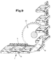
- FIG. 9 A further possibility of horizontally aligning the plate-shaped receptacle 1 in the region of the deflection points 30, 31 is shown in FIG. 9.
- a deflection sprocket 20 is provided and a guide plate 16 is combined with the deflection sprocket 20.
- An abutment pin 15 is provided on the plate-shaped receptacle 1, which comes to rest on the outer edge of the guide plate 16 and thereby guarantees the always horizontal position of the plate-shaped receptacle 1.
- the plate-shaped receptacle 1 are freely swingable on the conveyor chain 5 in that the support pin 4 with the interposition of ice pendulum plates 39 carries the receptacle 1.
- the receptacle 1 is rigidly attached to the pendulum plate.
Landscapes
- Life Sciences & Earth Sciences (AREA)
- Mycology (AREA)
- Environmental Sciences (AREA)
- Chemical & Material Sciences (AREA)
- Engineering & Computer Science (AREA)
- Food Science & Technology (AREA)
- Polymers & Plastics (AREA)
- Mushroom Cultivation (AREA)
- Sorting Of Articles (AREA)
- Medicines Containing Plant Substances (AREA)
- Chain Conveyers (AREA)
- Apparatuses For Bulk Treatment Of Fruits And Vegetables And Apparatuses For Preparing Feeds (AREA)
Abstract
Description
Die Erfindung bezieht sich auf eine Vorrichtung zum Transportieren von Pilzen in Pilzzuchtbetrieben.The invention relates to a device for transporting mushrooms in mushroom farms.
Aus der nicht vorveröffentlichten DE-39 10 230 C1 (angemeldet am 30.03.1989, veröffentlicht am 18.01.1990) ist eine Vorrichtung zum Sammeln, Transportieren und Abgeben von Pilzen bekanntgeworden, bei welcher eine Fördervorrichtung vorgesehen wird, die als Vertikalförderteil ausgebildet ist. Ein Trum dieses Vertikalförderteiles wird aus dem Vertikalteil ausgelenkt und zu einem Horizontalförderteil umfunktioniert, wobei die eigentliche Fördervorrichtung frei schwenkbare Sammelbehälter trägt, die stets mit ihrer offenen Seite nach oben gerichtet sind, unabhängig in welcher Richtung sie umlaufen, d. h. ob horizontal oder vertikal. Hierdurch wird erreicht, daß unabhängig von der Höhenlage des Horizontalförderers das Abgeben der Pilze an einem örtlich fixierten, feststehenden Punkt erfolgen kann, so daß hier Maßnahmen getroffen werden können, um ein beschädigungsloses Übergeben der Pilze vom Horizontalförderer zu den weiterverarbeitenden Stellen zu ermöglichen.DE-39 10 230 C1 (registered on March 30, 1989, published on January 18, 1990), which has not been published beforehand, has disclosed a device for collecting, transporting and dispensing mushrooms, in which a conveyor device is provided which is designed as a vertical conveyor part. A strand of this vertical conveying part is deflected out of the vertical part and converted into a horizontal conveying part, the actual conveying device carrying freely pivotable collecting containers which are always directed with their open side upwards, regardless of the direction in which they rotate, ie whether horizontally or vertically. This ensures that, regardless of the height of the horizontal conveyor, the mushrooms can be discharged at a locally fixed, fixed point, so that measures can be taken here to enable the mushrooms to be transferred from the horizontal conveyor to the processing points without damage.
Der Erfindung liegt die Aufgabe zugrunde, bei einer Vorrichtung zum Transportieren von Pilzen in Pilzzuchtbetrieben Maßnahmen vorzusehen, um automatisch während des Transportes des Pilzes ein Abschneiden des Fußes des geernteten Pilzes zu erreichen.The invention has for its object to provide measures in a device for transporting mushrooms in mushroom farms to automatically cut off the foot of the harvested mushroom during the transport of the mushroom.
Diese der Erfindung zugrundeliegende Aufgabe wird durch die Lehre des Hauptanspruches gelöst.This object on which the invention is based is achieved by the teaching of the main claim.
Vorteilhafte Ausgestaltungen sind in den Unteransprüchen erläutert.Advantageous configurations are explained in the subclaims.
Mit anderen Worten ausgedrückt wird vorgeschlagen, plattenförmige Aufnahmebehälter an einer umlaufenden Förderkette anzuordnen, wobei diese plattenförmigen Aufnahmebehälter eine Öffnung aufweisen, in die der Pilz eingesetzt werden kann. Diese Öffnung erweitert sich trichterförmig nach oben oder verjüngt sich trichterförmig nach unten, so daß in Abhängigkeit der Größe des Pilzkopfes der Pilzfuß mehr oder weniger weit durch die Öffnung nach unten zur Unterseite der plattenförmigen Aufnahmebehälter vorsteht. In den Weg der Förderkette und der daran angeordneten plattenförmigen Aufnahmebehälter ist ein Schneidmesser derart angeordnet, daß es bei der Förderbewegung des Aufnahmebehälters den über die Unterseite des plattenförmigen Aufnahmebehälters vorstehenden Pilzfuß abschneidet.In other words, it is proposed to arrange plate-shaped receptacles on a rotating conveyor chain, these plate-shaped receptacles having an opening into which the mushroom can be inserted. This opening widens upwards in a funnel shape or tapers downwards in a funnel shape, so that, depending on the size of the mushroom head, the mushroom foot protrudes more or less far through the opening down to the underside of the plate-shaped receptacle. In the path of the conveyor chain and the plate-shaped receptacles arranged thereon, a cutting knife is arranged such that it cuts off the mushroom foot protruding beyond the underside of the plate-shaped receptacle during the conveying movement of the receptacle.
Durch die erfindungsgemäße Einrichtung wird also erreicht, daß in der jeweiligen Höhe der in unterschiedlichen Höhen übereinander angeordneten Zuchtbeete ständig vorbeibewegte plattenförmige Aufnahmebehälter vorhanden sind, in die die Ernteperson den ergriffenen und abgeernteten Pilz einsetzt.With the device according to the invention it is thus achieved that at the respective height of the cultivation beds arranged one above the other at different heights, plate-shaped receptacles continuously moved past are present, in which the harvested person inserts the picked and harvested mushroom.
Diese plattenförmigen Aufnahmebehälter werden nun mit der Förderkette zu einer Sammelstelle geführt, wobei auf dem Weg zu dieser Sammelstelle die Schneidestation vorgesehen ist, in der das Abschneiden des Pilzfußes bei der Bewegung der Förderkette automatisch erfolgt.These plate-shaped receptacles are now led with the conveyor chain to a collection point, the cutting station being provided on the way to this collection point, in which the mushroom foot is cut off automatically when the conveyor chain moves.
Um sicherzustellen, daß die plattenförmigen Aufnahmebehälter stets eine horizontale Lage aufweisen, also der Pilz nicht aus diesen plattenförmigen Aufnahmebehältern herausfallen kann, gleichzeitig aber die plattenförmigen Aufnahmebehälter auch die erforderliche Stabilität besitzen, um den Widerstand zu überwinden, der beim Anfahren des Schneidmessers auftritt, sind die plattenförmigen Aufnahmebehälter gemäß einer ersten Ausführungsform der Erfindung mittels Tragzapfen an der Förderkette angeordnet, wobei die Tragzapfen in eine Öffnung im plattenförmigen Behälter greifen und hier nur schwer drehend den plattenförmigen Aufnahmebehälter halten. Um die stets horizontale Lage sicherzustellen, sind im Bereich der Umlenkrollen für die Förderkette Anschlagmittel oder Führungsmittel vorgesehen, die auf die plattenförmigen Aufnahmebehälter einwirken und die stets horizontale Lage dieser Aufnahmebehälter garantieren.To ensure that the plate-shaped receptacles always have a horizontal position, that is to say the mushroom cannot fall out of these plate-shaped receptacles, but at the same time the plate-shaped receptacles also have the necessary stability to overcome the resistance which occurs when the cutting knife is started up, these are plate-shaped receptacle arranged according to a first embodiment of the invention by means of trunnions on the conveyor chain, the trunnions engage in an opening in the plate-shaped container and here hold the plate-shaped receptacle only with difficulty rotating. In order to ensure the always horizontal position, stop means or guide means are provided in the area of the deflection rollers for the conveyor chain, which act on the plate-shaped receptacles and guarantee the always horizontal position of these receptacles.
Gemäß einer anderen Ausführungsform der Erfindung wird die horizontale Lage der plattenförmigen Aufnahmebehälter durch eine Gleitführung sichergestellt, in der das der Förderkette abgewandte Ende des plattenförmigen Aufnahmebehälters horizontal geführt wird. Diese Anordnung hat den Vorteil, daß die plattenförmigen Aufnahmebehälter an der Förderkette frei schwenkbar anschließen und dadurch die Umlenkeinrichtungen im Bereich der Umlenkung der Förderkette aus der horizontalen in die vertikale Lage nicht erforderlich sind (s. vergleichbar hierzu US-PS 48 46 337 bzw. DE-PS 35 25 460).According to another embodiment of the invention, the horizontal position of the plate-shaped receptacle is ensured by a sliding guide in which the end of the plate-shaped receptacle facing away from the conveyor chain is guided horizontally. This arrangement has the advantage that the plate-shaped receptacles connect freely pivotable to the conveyor chain and thereby the Deflection devices in the region of the deflection of the conveyor chain from the horizontal to the vertical position are not necessary (see comparable US-PS 48 46 337 or DE-PS 35 25 460).
Ausführungsbeispiele der Erfindung werden nachfolgend anhand der Zeichnungen erläutert. Die Zeichnungen zeigen dabei in den
- Fig. 1 bis 4 einen plattenförmigen Aufnahmebehälter in Draufsicht, in Unteransicht, im Schnitt gemäß der Linie A - A und im Schnitt gemäß der Linie B - B, in
- Fig. 5 eine Ansicht auf die an einer Förderkette angeschlossenen plattenförmigen Aufnahmebehälter, in
- Fig. 6 die Anordnung des Schneidmessers mit in einer Aufnahmeöffnung des plattenförmigen Aufnahmebehälters eingesetztem Pilz, in
- Fig. 7 eine Führungskette und eine Führungskurve zur Lagehalterung der plattenförmigen Aufnahmebehälter, in
- Fig. 8 eine Ansicht auf einen Teil der Führungskette in Fig. 7, in
- Fig. 9 eine abgeänderte Ausführungsform zur Lagestabilisierung der plattenförmigen Aufnahmebehälter, in
- Fig. 10 eine weitere abgeänderte Ausführungsform zur Lagestabilisierung der plattenförmigen Aufnahmebehälter im Bereich der Schneidestation und in
- Fig. 11 schematisch und schaubildlich eine Gesamtansicht auf einen mit Zuchtbeeten und Fördervorrichtung ausgerüsteten Pilzzuchtbetrieb.
- 1 to 4 a plate-shaped receptacle in plan view, in bottom view, in section along the line A - A and in section along the line B - B, in
- Fig. 5 is a view of the plate-shaped receptacle connected to a conveyor chain, in
- 6 shows the arrangement of the cutting knife with the mushroom inserted in a receiving opening of the plate-shaped receiving container, in
- Fig. 7 is a guide chain and a guide curve for holding the position of the plate-shaped receptacle, in
- Fig. 8 is a view of part of the guide chain in Fig. 7, in
- Fig. 9 shows a modified embodiment for stabilizing the position of the plate-shaped receptacle, in
- Fig. 10 shows another modified embodiment for stabilizing the position of the plate-shaped receptacle in the area of the cutting station and in
- 11 schematically and diagrammatically an overall view of a mushroom growing operation equipped with growing beds and conveying device.
In Fig. 11 ist schaubildlich ein Gestell 21 dargestellt, das Zuchtbeete 22, 23, 24 und 25 aufnimmt, in denen Pilze P, z. B. Champignons gezüchtet werden. Vor dem Gestell 21 ist eine von einem Motor 41 angetriebene Fördervorrichtung 27 vorgesehen, die aus einem Vertikalförderteil 28 und einem Horizontalförderteil 29 besteht, wobei von einer entsprechend umlaufend geführten Förderkette 5 (Fig. 5) Aufnahmebehälter 1 getragen werden, die schwenkbar aufgehängt sind, wie dies nachfolgend anhand weiterer Ausführungsbeispiele noch erläutert wird.In Fig. 11 a
Die Fördervorrichtung 27 führt zu einem Sammelband 35, auf das die in den Aufnahmebehältern 1 enthaltenen Pilze P abgegeben und abgefördert werden können.The
Vor der Übergabe auf das Sammelband 35 ist eine Schneidestation 34 angeordnet, in der der Fuß der Pilze P - wie nachfolgend erläutert wird - abgeschnitten wird. Im Bereich des Sammelbandes 35 wird über zusätzliche, in der Zeichnung nicht gesondert dargestellte mechanische Mittel der Aufnahmebehälter 1 so geschwenkt, daß ein Auskippen des Pilzes möglich ist.Before the transfer to the
Der Horizontalförderteil 29 ist an Tragseilen 36 befestigt, die zu einer motorisch angetriebenen Seilrolle 37 führen. Hierdurch ist der gesamte Horizontalförderteil 29 in der Höhe vor dem Gestell 21 heb- und senkbar. Die Auslenkung der eigentlichen Förderkette 5 erfolgt über zwei Umlenkstellen 30 und 31, die an einem höhenbeweglichen Gleitschlitten 32 gelagert sind, der an einer entsprechenden Führung 38 des Vertikalförderteiles 29 auf- und abgleiten kann.The
Es ist erkennbar, daß der Horizontalförderteil 29 in jeder beliebigen Höhenlage vor dem Gestell 21 und damit vor dem jeweiligen Zuchtbeet 22 bis 25 angeordnet und eingestellt werden kann, so daß ein einfaches Abgeben eines Pilzes in einen Aufnahmebehälter 1 möglich ist.It can be seen that the
In den Fig. 1 bis 10 sind plattenförmige Aufnahmebehälter 1 dargestellt, die z. B. rechteckige Grundgestalt aufweisen und eine mittlere Aufnahmeöffnung 2 besitzen. Die Aufnahmeöffnung 2 ist dabei rund und trichterförmig ausgebildet und verjüngt sich von der Oberseite des plattenförmigen Aufnahmebehälters 1 zur Unterseite hin, so wie dies besonders deutlich die Fig. 3 und 4 sowie 6 und 10 zeigen.1 to 10 plate-
Der plattenförmige Aufnahmebehälter 1 besteht aus einem Spritzgußteil und weist eine Öffnung 3 für einen an der Förderkette 5 angeordneten Tragzapfen 4 auf. Der Durchmesser des Tragzapfens 4 ist bei einer ersten Ausführungsform gemäß den Fig. 6 bis 9 dabei so auf die Aufnahmeöffnung 3 abgestimmt, daß nur ein schwergängiges Drehen des plattenförmigen Aufnahmebehälters 1 an dem Tragzapfen 4 möglich ist, so daß diese Drehbewegung nicht von alleine eintritt, sondern über entsprechende Anschlagmittel eingeleitet und aufrechterhalten werden muß.The plate-
An der Unterseite des plattenförmigen Aufnahmebehälters 1 ist die eigentliche Aufnahmeöffnung 2 über die Unterkante eines Randes 6 nach unten hin etwas verlängert, so wie dies die Fig. 6 und die Fig. 3 deutlich zeigen, indem nämlich Aufgleitstege 9 und 10 geschaffen werden, die der Führung des in den Fig. 6 und 10 dargestellten Schneidmessers 11 dienen. Durch die trichterförmige Ausbildung der Aufnahmeöffnung 2 kann der in diese Aufnahmeöffnung 2 einzusetzende Pilz P mehr oder weniger weit nach unten durchtreten, so wie dies von der Größe des Pilzkopfes abhängt. Hierdurch wird immer die richtige Stelle für den Ansatz des Schneidmessers 11 beim Abschneiden des eigentlichen Pilzfußes sichergestellt.On the underside of the plate-
In Fig. 3 ist der obere Randbereich der Aufnahmeöffnung 2 mit 7 und der untere Randbereich mit 8 bezeichnet.In Fig. 3, the upper edge area of the receiving
Der von der Förderkette 5 getragene Tragzapfen 4 (Fig. 6) greift mittig an einer Schmalseite des plattenförmigen Aufnahmebehälters 1 an.The carrying pin 4 (FIG. 6) carried by the
Fig. 6 soll verdeutlichen, daß, wenn der plattenförmige Aufnahmebehälter 1 in den Bereich des Schneidmessers 11 geführt wird, das Schneidmesser 11 sich an der schrägen Kante der Stege 9 und 10 führt und damit ein sicheres Abschneiden des eigentlichen Pilzfußes gewährleistet wird.Fig. 6 is intended to illustrate that when the plate-
Die Fig. 7 zeigt, wie die eigentliche Förderkette 5 über das Umlenkrad 18 aus einer horizontalen in eine vertikale Lage umgelenkt wird. Hierbei würden normalerweise auch die plattenförmigen Aufnahmebehälter 1 aus der horizontalen in die vertikale Lage geschwenkt, da sie nicht frei pendelnd an der Förderkette 5 aufgehängt sind. Um trotzdem stets eine horizontale Lage der plattenförmigen Aufnahmebehälter 1 zu gewährleisten, ist im Bereich der Umlenkstellen 30 und 31 jeweils eine zusätzliche Förderkette 12 und ein zusätzliches Umlenkkettenrad 18a vorgesehen. Die zusätzliche Förderkette 12 weist Widerlagerstifte 14 auf (Fig. 8), die in den Weg der plattenförmigen Aufnahmebehälter 1 greifen und dabei eine Randkante des plattenförmigen Aufnahmebehälters 1 sobeaufschlagen, daß der plattenförmige Aufnahmebehälter 1 stets in der horizontalen Lage an dem Tragzapfen 4 und damit der Kette 5 gehalten wird.FIG. 7 shows how the
Das gleiche Problem tritt bei dem Umlenkrad 19 auf, und hier ist eine Führungskurve 17 vorgesehen, die für die stets horizontale Lage der plattenförmigen Aufnahmebehälter 1 Sorge trägt. Wie dies die Fig. 7 zeigt, legen sich die Randkanten der plattenförmigen Aufnahmebehälter 1 an das Innere der Führungskurve 17 bei Umlenkung der Förderkette 5 um das Umlenkkettenrad 19 an.The same problem occurs with the
Eine weitere Möglichkeit, die plattenförmigen Aufnahmebehälter 1 im Bereich der Umlenkstellen 30, 31 horizontal auszurichten, zeigt Fig. 9. Hier ist ein Umlenkkettenrad 20 vorgesehen und mit dem Umlenkkettenrad 20 ist ein Führungsblech 16 kombiniert. An den plattenförmigen Aufnahmebehältern 1 ist ein Widerlagerstift 15 vorgeshen, der an der Außenkante des Führungsbleches 16 zur Anlage kommt und dadurch die stets horizontale Lage der plattenförmigen Aufnahmebehälter 1 garantiert.A further possibility of horizontally aligning the plate-
Bei einer abgeänderten Ausführungsform, die anhand von Fig. 10 erläutert wird, sind die plattenförmigen Aufnahmebehälter 1 frei pendelbar an der Förderkette 5 dadurch angeordnet, daß der Tragzapfen 4 unter Zwischenschaltung eis Pendelbleches 39 den Aufnahmebehälter 1 trägt. Der Aufnahmebehälter 1 ist dabei starr an dem Pendelblech befestigt.In a modified embodiment, which is explained with reference to FIG. 10, the plate-shaped
Wie dies aus dem deutschen Patent 35 25 460 bzw. dem US-Patent 48 46 337 bekannt ist, bleibt dadurch der Aufnahmebehälter 1 trotz Umlenkung der Förderkette 5 aus der horizontalen in die vertikale Lage stets horizontal ausgerichtet. Um nunmehr den Aufnahmebehälter 1 im Bereich der Schneidestation 34 festzulegen, damit das Schneidmesser 11 den Pilzfuß des Pilzes P einwandfrei abschneiden kann, ist eine Gleitführung 40 vorgesehen, in der das der Förderkette 5 abgewandte Ende des Aufnahmebehälters 1 in horizontaler Ausrichtung festgelegt wird.As is known from
Claims (10)
- Device for transporting mushrooms in mushroom cultivating concerns, characterised by a powered, where necessary vertically adjustable, conveyor device (27), which is configured to circulate in front of the culture beds (22, 23, 24, 25), having a conveyor chain (5) on which plate-shaped receiving containers (1) are centrally disposed pivotably about a horizontal supporting journal (4), each plate-shaped receiving container (1) exhibiting a receiving opening (2) for receiving a mushroom (P) and a cutting bay (34) being provided in the path of the plate-shaped receiving container (1), in which cutting bay there is disposed, level with the bottom edge of the receiving container (1), a cutting blade (11), which cuts off the base of the mushroom protruding downwards out of the receiving opening (2) beyond the bottom edge of the plate-shaped receiving container (1).
- Device according to Claim 1, characterised in that the receiving opening (2) is configured in the shape of a funnel.
- Device according to Claim 1 or 2, characterised in that the lower border (8) of the receiving opening (2) protrudes beyond the border (6) of the plate-shaped receiving container (1).
- Device according to one or more of the preceding claims, characterised in that there are disposed on the underside of the plate-shaped receiving container (1) bars (9, 10), which extend transversely to the longitudinal axis from the border (6) of the plate-shaped receiving container (1) to the lower border (8) of the receiving opening (2).
- Device according to one or more of the preceding claims, characterised in that the plate-shaped receiving containers (1) consist of a plastic injection-moulded part.
- Device according to one or more of the preceding Claims 1 to 5, characterised in that the supporting journal (4) is disposed in a clamping manner in a supporting opening (3) in the receiving container (1) and in that, in the area of the deflection of the conveyor chain (5) from a horizontal into a vertical or from a vertical into a horizontal direction, stop means or guide means are provided, which bring about a constantly horizontal position of the plate-shaped receiving containers (1) on the conveyor chain (5).
- Device according to Claim 6, characterised in that, as the guide means, a circulating chain (12) is provided, which is equipped with abutment pins (14) protruding into the path of the plate-shaped receiving container (1) and which is guided such that, in the area of the deflection of the conveyor chain (5), the plate-shaped receiving containers (1) are kept horizontal.
- Device according to Claim 6, characterised in that the plate-shaped receiving containers (1) exhibit an abutment pin (15), which is disposed off-centre on the narrow side of the plate-shaped receiving container (1) and, in the area of the deflection of the conveyor chain (5), comes into contact with a guide plate (16) which has the effect of the plate-shaped receiving containers (1) being held constantly in a horizontal position.
- Device according to Claim 6, characterised by a guide curve (17) disposed in the area of the deflection, which guide curve is disposed at a distance from the conveyor chain (5) such that the plate-shaped receiving containers (1) remain constantly in the horizontal position despite the deflection of the conveyor chain (5).
- Device according to one or more of the preceding Claims 1 to 6, characterised in that, in the area of the cutting bay (34), the receiving container (1) is guided by its end facing away from the conveyor chain (5), in a pivot-proof manner, in a U-shaped slideway (40), the supporting journal (4) fixed to the conveyor chain (5) being disposed in a freely pivotable manner in the supporting opening (3).
Priority Applications (1)
| Application Number | Priority Date | Filing Date | Title |
|---|---|---|---|
| AT90102527T ATE83888T1 (en) | 1989-07-27 | 1990-02-09 | DEVICE FOR TRANSPORTING MUSHROOMS IN MUSHROOM FARMS. |
Applications Claiming Priority (2)
| Application Number | Priority Date | Filing Date | Title |
|---|---|---|---|
| DE3924870 | 1989-07-27 | ||
| DE3924870A DE3924870C1 (en) | 1989-07-27 | 1989-07-27 |
Publications (2)
| Publication Number | Publication Date |
|---|---|
| EP0410073A1 EP0410073A1 (en) | 1991-01-30 |
| EP0410073B1 true EP0410073B1 (en) | 1992-12-30 |
Family
ID=6385970
Family Applications (1)
| Application Number | Title | Priority Date | Filing Date |
|---|---|---|---|
| EP90102527A Expired - Lifetime EP0410073B1 (en) | 1989-07-27 | 1990-02-09 | Device for transporting mushrooms in mushroom growing rooms |
Country Status (9)
| Country | Link |
|---|---|
| US (1) | US5081920A (en) |
| EP (1) | EP0410073B1 (en) |
| AT (1) | ATE83888T1 (en) |
| DD (1) | DD295604A5 (en) |
| DE (2) | DE3924870C1 (en) |
| DK (1) | DK0410073T3 (en) |
| ES (1) | ES2038006T3 (en) |
| GR (1) | GR3007196T3 (en) |
| RU (1) | RU1777549C (en) |
Families Citing this family (17)
| Publication number | Priority date | Publication date | Assignee | Title |
|---|---|---|---|---|
| DE4215146A1 (en) * | 1992-05-08 | 1993-11-11 | Klaus Dr Seidel | Device for cooking dough portions |
| NL9500104A (en) * | 1995-01-20 | 1996-09-02 | Ccm Beheer Bv | Stem crop guide. |
| GB9621582D0 (en) * | 1996-10-16 | 1996-12-04 | Russell Tony A | Handling of mushrooms |
| IES980319A2 (en) * | 1998-04-28 | 2000-10-04 | John Hayes | Apparatus and method for processing and packing mushrooms |
| DE29910876U1 (en) * | 1999-06-29 | 2000-11-30 | Wiesenhof-Pilzland Vertriebsgesellschaft mbH, 49429 Visbek | Apparatus for harvesting mushrooms, transport device and container for receiving mushrooms |
| DE19929510A1 (en) * | 1999-06-29 | 2001-01-04 | Wiesenhof Pilzland Vertriebsgm | Method and device for processing mushrooms or the like |
| NL1017453C2 (en) | 2001-02-26 | 2002-08-27 | Champignonkwekerij Van Doremae | Method for picking and further processing of mushrooms grown in beds, boxes, containers or similar involves hand picking and placing of mushrooms into drawers placed in racks next to beds, boxes, containers or similar |
| BE1014812A3 (en) * | 2002-05-03 | 2004-04-06 | Districhamp N V | Device for cutting and transport of picked mushrooms. |
| EP1810563A1 (en) * | 2006-01-24 | 2007-07-25 | Gerardus Jacobus Wilhelmus Verdellen | Arrangement and method for manually harvesting and processing mushrooms |
| US20130340329A1 (en) * | 2010-12-22 | 2013-12-26 | Hendrik van den Top | Harvesting Device, Grow Space, Grow System and Method |
| BE1025212B1 (en) * | 2017-05-08 | 2018-12-10 | Delfort Comm. V. | DEVICE FOR TRANSPORTING MUSHROOMS |
| WO2018207085A1 (en) * | 2017-05-08 | 2018-11-15 | Delfort Comm. V. | Device for conveying mushrooms |
| CN107668746B (en) * | 2017-11-03 | 2023-06-23 | 漳州职业技术学院 | Mushroom fungus pole excision device |
| US11297777B2 (en) * | 2018-05-01 | 2022-04-12 | John H. Oberthier | Apparatus and methods for growing organic matter |
| NL2024283B1 (en) * | 2019-11-21 | 2021-08-18 | Cornelissen/Derkx Beheer B V | Device for growing mushrooms |
| CN112056156B (en) * | 2020-09-03 | 2022-08-02 | 刘国强 | Automatic white fungus picking machine of pay-off |
| CN112715145A (en) * | 2021-01-25 | 2021-04-30 | 吕和辉 | Tremella cutting equipment |
Family Cites Families (19)
| Publication number | Priority date | Publication date | Assignee | Title |
|---|---|---|---|---|
| US2243530A (en) * | 1938-06-08 | 1941-05-27 | Kok Albert | Apparatus for pitting cherries |
| US2307665A (en) * | 1940-04-26 | 1943-01-05 | Carmichael Machine Company | Conveyer |
| US2712334A (en) * | 1950-01-11 | 1955-07-05 | Edward W Bridge | Vegetable orienting and trimming machine |
| US2935176A (en) * | 1959-02-19 | 1960-05-03 | Lorenzen Coby | Fruit orienting device |
| US3080902A (en) * | 1960-10-07 | 1963-03-12 | Sidney Ross | Produce centering arrangement |
| US3537495A (en) * | 1967-07-28 | 1970-11-03 | William S Pearson | Mushroom cutting machine |
| US3567011A (en) * | 1968-10-18 | 1971-03-02 | Reynolds Tobacco Co R | Cigarette transfer apparatus for changing direction and reducing velocity of cigarettes |
| US3605984A (en) * | 1969-07-07 | 1971-09-20 | Borden Inc | Apparatus for orienting core-bearing fruit |
| US3734004A (en) * | 1970-10-19 | 1973-05-22 | Losito Mushroom Corp | Automatic mushroom trimming machine |
| FR2164997A5 (en) * | 1971-12-14 | 1973-08-03 | Aubert Maguero Paul | Mushroom handling device - for centring stems of mushrooms in tubes |
| US3832802A (en) * | 1973-02-12 | 1974-09-03 | T Huys | Apparatus and method for cultivating plants |
| FR2384462A1 (en) * | 1977-01-12 | 1978-10-20 | Bournier Edgard | Installation for trimming cultivated mushrooms - conveys them from wash tank with stalks correctly orientated for trimming heads |
| US4168642A (en) * | 1977-10-28 | 1979-09-25 | Green Giant Company | Broccoli quartering machine |
| FR2419033A1 (en) * | 1978-03-09 | 1979-10-05 | Peruffo Alessandro | Machine to size grade and trim dry mushrooms - sorts sizes via divergent conveyor bands and trims stalks to equal lengths |
| DE3640816C1 (en) * | 1985-07-17 | 1988-02-11 | Josef Kuehlmann | Egg transport device |
| NL8701239A (en) * | 1987-05-22 | 1988-12-16 | Top Hendrik Van Den | APPARATUS FOR GROWING GARDEN CONSTRUCTION PRODUCTS, IN PARTICULAR MUSHROOMS. |
| US4913044A (en) * | 1988-02-10 | 1990-04-03 | Lindsay Olive Growers | Apparatus for cutting a work object |
| JPH02289165A (en) * | 1988-12-07 | 1990-11-29 | Nordson Corp | Apparatus for applying adhesive to elastic string |
| DE3910230C1 (en) * | 1989-03-30 | 1990-01-18 | Josef 4419 Laer De Kuehlmann | Apparatus for collecting, transporting and discharging mushrooms |
-
1989
- 1989-07-27 DE DE3924870A patent/DE3924870C1/de not_active Expired - Lifetime
-
1990
- 1990-02-09 ES ES199090102527T patent/ES2038006T3/en not_active Expired - Lifetime
- 1990-02-09 EP EP90102527A patent/EP0410073B1/en not_active Expired - Lifetime
- 1990-02-09 DK DK90102527.0T patent/DK0410073T3/en active
- 1990-02-09 DE DE9090102527T patent/DE59000684D1/en not_active Expired - Fee Related
- 1990-02-09 AT AT90102527T patent/ATE83888T1/en not_active IP Right Cessation
- 1990-06-07 US US07/534,740 patent/US5081920A/en not_active Expired - Fee Related
- 1990-07-25 DD DD90343068A patent/DD295604A5/en not_active IP Right Cessation
- 1990-07-26 RU SU904830537A patent/RU1777549C/en active
-
1993
- 1993-03-02 GR GR930400441T patent/GR3007196T3/el unknown
Also Published As
| Publication number | Publication date |
|---|---|
| RU1777549C (en) | 1992-11-23 |
| ES2038006T3 (en) | 1993-07-01 |
| DK0410073T3 (en) | 1993-03-08 |
| DD295604A5 (en) | 1991-11-07 |
| US5081920A (en) | 1992-01-21 |
| DE3924870C1 (en) | 1990-07-26 |
| GR3007196T3 (en) | 1993-07-30 |
| DE59000684D1 (en) | 1993-02-11 |
| EP0410073A1 (en) | 1991-01-30 |
| ATE83888T1 (en) | 1993-01-15 |
Similar Documents
| Publication | Publication Date | Title |
|---|---|---|
| EP0410073B1 (en) | Device for transporting mushrooms in mushroom growing rooms | |
| DE69016963T2 (en) | Device for automatically setting up and conveying containers. | |
| DE69000502T2 (en) | DEVICE FOR CONVEYING OBJECTS, LIKE FILLED BAGS, FROM A CONVEYOR TO A COLLECTING DEVICE, LIKE A CARDBOARD UNDER THIS CONVEYOR. | |
| EP1160166B1 (en) | Apparatus for forming groups and method of operating the same | |
| DE3887533T2 (en) | METHOD AND DEVICE FOR REMOVING RIBBONS FROM BUNCHES OF LETTERS. | |
| DE69005772T2 (en) | Apparatus for harvesting mushrooms. | |
| DE2415376A1 (en) | DEVICE FOR PACKING EGGS IN CONTAINERS | |
| DE2807236C2 (en) | Planting machine for potatoes, onions or the like | |
| EP4417039A2 (en) | System for cultivating and harvesting mushrooms | |
| EP2200791B1 (en) | Depositing/transporting-away device for cut foodstuff and food cutting machine | |
| DE2205172C2 (en) | Extraction device for driving silos | |
| DE60102601T2 (en) | Method and device for conveying objects | |
| DE2027372A1 (en) | ||
| DE3910230C1 (en) | Apparatus for collecting, transporting and discharging mushrooms | |
| DE3943281A1 (en) | DEVICE FOR COLLECTING FISH EGGS | |
| DD264139A5 (en) | DEVICE FOR WORKING FLOOR BODIES | |
| DE19642823A1 (en) | Automatic handling machine for inserting plants in pots | |
| EP0536507B1 (en) | Device for splitting a whole cheese | |
| DE3114718A1 (en) | "DEVICE FOR STACKING SHEET METAL CUTTINGS IN TABLE SCISSORS" | |
| DE19700512B4 (en) | Sorting and feeding machine | |
| DE102015105615B4 (en) | Harvesting blade for a harvesting device and a harvesting device, a harvesting system and a method for automated harvesting of crops | |
| DE19613634A1 (en) | Plastic scrap processing machine suitable for bottles and baled scrap | |
| DE1556096B2 (en) | DEVICE FOR REMOVING LIGHT MOLDED PARTS FROM A COLLECTION CONTAINER OF A STEEP CONVEYOR | |
| DE269185C (en) | ||
| DE599254C (en) | Conveyor belt with tail grippers for fish processing machines |
Legal Events
| Date | Code | Title | Description |
|---|---|---|---|
| PUAI | Public reference made under article 153(3) epc to a published international application that has entered the european phase |
Free format text: ORIGINAL CODE: 0009012 |
|
| AK | Designated contracting states |
Kind code of ref document: A1 Designated state(s): AT BE CH DE DK ES FR GB GR IT LI NL SE |
|
| 17P | Request for examination filed |
Effective date: 19901212 |
|
| 17Q | First examination report despatched |
Effective date: 19920506 |
|
| GRAA | (expected) grant |
Free format text: ORIGINAL CODE: 0009210 |
|
| AK | Designated contracting states |
Kind code of ref document: B1 Designated state(s): AT BE CH DE DK ES FR GB GR IT LI NL SE |
|
| REF | Corresponds to: |
Ref document number: 83888 Country of ref document: AT Date of ref document: 19930115 Kind code of ref document: T |
|
| REF | Corresponds to: |
Ref document number: 59000684 Country of ref document: DE Date of ref document: 19930211 |
|
| ET | Fr: translation filed | ||
| ITF | It: translation for a ep patent filed | ||
| REG | Reference to a national code |
Ref country code: DK Ref legal event code: T3 |
|
| GBT | Gb: translation of ep patent filed (gb section 77(6)(a)/1977) |
Effective date: 19930209 |
|
| REG | Reference to a national code |
Ref country code: GR Ref legal event code: FG4A Free format text: 3007196 |
|
| REG | Reference to a national code |
Ref country code: ES Ref legal event code: FG2A Ref document number: 2038006 Country of ref document: ES Kind code of ref document: T3 |
|
| PLBE | No opposition filed within time limit |
Free format text: ORIGINAL CODE: 0009261 |
|
| STAA | Information on the status of an ep patent application or granted ep patent |
Free format text: STATUS: NO OPPOSITION FILED WITHIN TIME LIMIT |
|
| 26N | No opposition filed | ||
| EAL | Se: european patent in force in sweden |
Ref document number: 90102527.0 |
|
| PGFP | Annual fee paid to national office [announced via postgrant information from national office to epo] |
Ref country code: SE Payment date: 19951128 Year of fee payment: 7 |
|
| PGFP | Annual fee paid to national office [announced via postgrant information from national office to epo] |
Ref country code: GR Payment date: 19960124 Year of fee payment: 7 |
|
| PGFP | Annual fee paid to national office [announced via postgrant information from national office to epo] |
Ref country code: FR Payment date: 19960126 Year of fee payment: 7 |
|
| PGFP | Annual fee paid to national office [announced via postgrant information from national office to epo] |
Ref country code: DE Payment date: 19960129 Year of fee payment: 7 |
|
| PGFP | Annual fee paid to national office [announced via postgrant information from national office to epo] |
Ref country code: GB Payment date: 19960131 Year of fee payment: 7 |
|
| PGFP | Annual fee paid to national office [announced via postgrant information from national office to epo] |
Ref country code: BE Payment date: 19960207 Year of fee payment: 7 |
|
| PGFP | Annual fee paid to national office [announced via postgrant information from national office to epo] |
Ref country code: ES Payment date: 19960216 Year of fee payment: 7 |
|
| PGFP | Annual fee paid to national office [announced via postgrant information from national office to epo] |
Ref country code: CH Payment date: 19960223 Year of fee payment: 7 |
|
| PGFP | Annual fee paid to national office [announced via postgrant information from national office to epo] |
Ref country code: AT Payment date: 19960226 Year of fee payment: 7 |
|
| PGFP | Annual fee paid to national office [announced via postgrant information from national office to epo] |
Ref country code: DK Payment date: 19960227 Year of fee payment: 7 |
|
| PGFP | Annual fee paid to national office [announced via postgrant information from national office to epo] |
Ref country code: NL Payment date: 19960229 Year of fee payment: 7 |
|
| PG25 | Lapsed in a contracting state [announced via postgrant information from national office to epo] |
Ref country code: GB Effective date: 19970209 Ref country code: DK Effective date: 19970209 Ref country code: AT Effective date: 19970209 |
|
| REG | Reference to a national code |
Ref country code: DK Ref legal event code: EBP |
|
| PG25 | Lapsed in a contracting state [announced via postgrant information from national office to epo] |
Ref country code: SE Effective date: 19970210 Ref country code: ES Free format text: LAPSE BECAUSE OF NON-PAYMENT OF DUE FEES Effective date: 19970210 |
|
| PG25 | Lapsed in a contracting state [announced via postgrant information from national office to epo] |
Ref country code: LI Effective date: 19970228 Ref country code: CH Effective date: 19970228 Ref country code: BE Effective date: 19970228 |
|
| BERE | Be: lapsed |
Owner name: KUHLMANN JOSEF Effective date: 19970228 |
|
| PG25 | Lapsed in a contracting state [announced via postgrant information from national office to epo] |
Ref country code: GR Free format text: THE PATENT HAS BEEN ANNULLED BY A DECISION OF A NATIONAL AUTHORITY Effective date: 19970831 |
|
| PG25 | Lapsed in a contracting state [announced via postgrant information from national office to epo] |
Ref country code: NL Effective date: 19970901 |
|
| REG | Reference to a national code |
Ref country code: GR Ref legal event code: MM2A Free format text: 3007196 |
|
| GBPC | Gb: european patent ceased through non-payment of renewal fee |
Effective date: 19970209 |
|
| REG | Reference to a national code |
Ref country code: CH Ref legal event code: PL |
|
| PG25 | Lapsed in a contracting state [announced via postgrant information from national office to epo] |
Ref country code: FR Effective date: 19971030 |
|
| PG25 | Lapsed in a contracting state [announced via postgrant information from national office to epo] |
Ref country code: DE Effective date: 19971101 |
|
| EUG | Se: european patent has lapsed |
Ref document number: 90102527.0 |
|
| NLV4 | Nl: lapsed or anulled due to non-payment of the annual fee |
Effective date: 19970901 |
|
| REG | Reference to a national code |
Ref country code: FR Ref legal event code: ST |
|
| REG | Reference to a national code |
Ref country code: ES Ref legal event code: FD2A Effective date: 19990405 |
|
| PG25 | Lapsed in a contracting state [announced via postgrant information from national office to epo] |
Ref country code: IT Free format text: LAPSE BECAUSE OF NON-PAYMENT OF DUE FEES;WARNING: LAPSES OF ITALIAN PATENTS WITH EFFECTIVE DATE BEFORE 2007 MAY HAVE OCCURRED AT ANY TIME BEFORE 2007. THE CORRECT EFFECTIVE DATE MAY BE DIFFERENT FROM THE ONE RECORDED. Effective date: 20050209 |