EP0408417A1 - Klassierungs- und Einschliessungsvorrichtung für von einem Traktor gezogenen Stein-Schwadformer, der zwei in bezug auf die Fahrtrichtung des Traktors im "V" ausgebreitete Schenkel besitzt, die ausserdem nachgiebige und schwingungsfähige Zahnungen tragen - Google Patents
Klassierungs- und Einschliessungsvorrichtung für von einem Traktor gezogenen Stein-Schwadformer, der zwei in bezug auf die Fahrtrichtung des Traktors im "V" ausgebreitete Schenkel besitzt, die ausserdem nachgiebige und schwingungsfähige Zahnungen tragen Download PDFInfo
- Publication number
- EP0408417A1 EP0408417A1 EP90401876A EP90401876A EP0408417A1 EP 0408417 A1 EP0408417 A1 EP 0408417A1 EP 90401876 A EP90401876 A EP 90401876A EP 90401876 A EP90401876 A EP 90401876A EP 0408417 A1 EP0408417 A1 EP 0408417A1
- Authority
- EP
- European Patent Office
- Prior art keywords
- teeth
- stones
- swather
- tractor
- vibrating
- Prior art date
- Legal status (The legal status is an assumption and is not a legal conclusion. Google has not performed a legal analysis and makes no representation as to the accuracy of the status listed.)
- Granted
Links
Images


Classifications
-
- A—HUMAN NECESSITIES
- A01—AGRICULTURE; FORESTRY; ANIMAL HUSBANDRY; HUNTING; TRAPPING; FISHING
- A01B—SOIL WORKING IN AGRICULTURE OR FORESTRY; PARTS, DETAILS, OR ACCESSORIES OF AGRICULTURAL MACHINES OR IMPLEMENTS, IN GENERAL
- A01B43/00—Gatherers for removing stones, undesirable roots or the like from the soil, e.g. tractor-drawn rakes
- A01B43/005—Windrower-type machines
-
- A—HUMAN NECESSITIES
- A01—AGRICULTURE; FORESTRY; ANIMAL HUSBANDRY; HUNTING; TRAPPING; FISHING
- A01B—SOIL WORKING IN AGRICULTURE OR FORESTRY; PARTS, DETAILS, OR ACCESSORIES OF AGRICULTURAL MACHINES OR IMPLEMENTS, IN GENERAL
- A01B35/00—Other machines for working soil
- A01B35/20—Tools; Details
- A01B35/22—Non-rotating tools; Resilient or flexible mounting of rigid tools
- A01B35/24—Spring tools
-
- A—HUMAN NECESSITIES
- A01—AGRICULTURE; FORESTRY; ANIMAL HUSBANDRY; HUNTING; TRAPPING; FISHING
- A01D—HARVESTING; MOWING
- A01D33/00—Accessories for digging harvesters
- A01D33/10—Crop collecting devices, with or without weighing apparatus
- A01D33/105—Devices for gathering the crop in a row
Definitions
- the present invention relates to a device for calibrating and confining a stone swather pulled by a tractor, of the type comprising two axes, deployed in a "V" shape relative to the axis of advance of the tractor, these axes also bearing toothing. flexible and vibrant.
- the rotor On a machine of the first type, the rotor, by turning, migrates the stones cluttering the ground to the side, where they form a swath which can then be picked up or crushed on site.
- Rotor rakes are nevertheless heavy, expensive, and sluggish machines, which in particular require connecting the rotor to the power source of the tractor providing traction.
- a rake of the second type provides the advantage of simplicity.
- This general configuration of stone swathers is found in French patents FR-1,283,266, FR-2,344,210 and FR-2,340,673.
- the conventional rigid teeth do not ensure any selection between soil, stones, roots and other plant debris, the swath formed at the rear of the machine being thus very heterogeneous and difficult to treat.
- a rigid toothing quickly becomes cluttered and no longer performs its raking work after a certain time.
- the present invention aims to remedy this drawback by proposing a calibration and containment device for swath of stones with oblique arms deployed in a "V" shape and provided with vibrating teeth arranged in a comb, characterized in that at least one bar, or a series of shorter bars arranged in succession, is arranged outside the comb of the vibrating teeth carried by each arm, in a direction substantially parallel to the direction of this arm, and at a determining height relative to the ground, with the spacing of the teeth between them, the maximum size of the stones being able to escape laterally at l outside of the "V" after having been raked upstream of the swather.
- the device according to the invention thus advantageously remedies the aforementioned drawbacks of swaths with "V" arms.
- One of its goals is to further strengthen the efficiency of the alignment of the stones, especially on difficult, muddy terrain, cluttered with plant debris, or of uneven level.
- Another of its aims is to improve the selectivity of the teeth by amplifying the phenomenon of vibration of these.
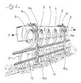
- the stone swather 1 comprises a set of two arms 2 deployed in "V", converging towards their rear end 3, so as to leave a passage 4 along the axis of movement swather 1, which preferably shares said "V” in two equal surfaces.
- Each of the arms 2 carries a row of vibrating teeth 5 arranged in a comb in a plane substantially parallel to the vertical median plane of the swather 1.
- These teeth 5 may, for example, have a classic "swan neck” shape, the posterior claw 6 (fig. 2,3) of a tooth 5 turning its concavity towards the front of the swather 1, so as to excavate the surface of the soil 7 and to bring to the surface the stones which are buried there.
- the swather 1 is pulled behind a tractor 8, schematically represented in FIG. 1, via, for example, a three-point lifting device, running on a tractor 8, of which only two of the points are seen.
- articulation 9 Pivoting bearing wheels 10, located at the front end 11 of the arms 2 making up the "V" of the swather 1, and carrying wheels 12 located at the rear end 3 of said arms 2, make it possible to move the swather 1 and are also adjustable in height, so that the vibrating teeth 5 can be driven into the ground 7.
- the spacing of two teeth 5, in relation to the height of the part of these teeth 5 not sunk into the ground 7, provide a first calibration of the stones.
- a bar 13, or a series of shorter bars 13 arranged longitudinally in succession, is arranged outside the row of vibrating teeth 5 carried by each arm 2, in a direction substantially parallel to the direction of these arms 2.
- the operation of the swather 1 described above is as follows: the tractor 8, attached by the fixing points 9 to the swather 1, pulls it in the direction of the arrow F, so that the "V "has its base backwards.
- the stones dug up all along the arms 2 by the action of the vibrating teeth 5, are pushed back progressively during the advancement of the tractor 8 and the swather 1, towards the posterior ends 3 of the arms 2, where they are grouped together and form a swath whose width is substantially equal to the width of the passage 4 provided for this purpose between the ends 3 of the arms 2.
- the bar 13, or the series of bars 13, then advantageously makes it possible to confine the stones encumbering the interstice of two or more vibrating teeth 5 and prevent their lateral escape outside said "V". It should be noted that a series of substantially aligned bars 13 is preferably used, shorter than a single bar 13 disposed along an arm 2, and therefore more manageable.
- the ground clearance of the bars 13 is adjustable and, unexpectedly, allows a second calibration of the stones dug up by the vibrating teeth 5, so as to leave only stones on the ground 7, behind the swather 1 whose size does not interfere with crops.
- This means 14 can, without limitation, be a screw system, a slide system, a hydraulic system, a pneumatic system, a sliding system, etc.
- curved bars 16 can slide in the slides 15 and are integral with the bars 13 at their lower end.
- the clearance provided by the outward curvature of the bars 36 advantageously provides an intervention space above the teeth 5 and in particular makes it possible to easily replace them in the event of breakage.
- Another adjustment means 14 is shown in FIG. 2: straight bars 16a are fixed to the arm 2 and a slide 15a, integral with the bars 13, makes it possible to adjust their height relative to the ground.
- the bars 13 are in permanent contact with the teeth 5, and according to their height relative to the ground, are in positive support on a different part of the teeth 5.
- This arrangement significantly improves the efficiency of the calibration and confinement device according to the invention.
- this permanent contact of the bars 13 with the teeth 5 provides an unexpected advantage which appreciably improves the selectivity of the vibrating teeth 5, with respect to the stones, with respect to the gangue of earth which surrounds them, at the roots, or other plant debris present in the soil 7.
- the teeth 5 in fact transmit their vibration to the bar 13 or to the bars 13, this vibration therefore being amplified along an arm 2, which makes it possible to separate all the better. the stones of the earth.
- bars 13 which are normally made of metal, but can be made of any other material usual in the field of agriculture.
- the shape of these bars 13 is also indifferent to their effectiveness; they can be round, flat, "U” -shaped, in the form of angles or other profiles.
- the arms 2, constituting the "V" of the swather 1 are articulated so that the vertical lifting of one of their part 17 allows the transport of the swather 1 on the road.
- This lifting system is distinct from the three-point lifting device, conventionally present on the tractor 8, and which only allows the entire swather 1 to be raised relative to the ground 7.
- the device for lifting the arms 2 vertically, and which makes it possible to reduce the lateral dimensions of the swather 1, is produced, for example, in the following manner: the frame 18 connecting together the arm 2 of the swather 1, is articulated along the longitudinal axis of advancement of the swather 1, by means of hinges 19, the locking and locking of which in the open position is ensured by flanges 20, now for this purpose , between them, the parts of the chassis 18 separated by the hinges 19.
- a device with jacks 21 connecting a part 22 of the chassis 18 of the swather 1 to the movable part 17 of the arms 2, essentially ensures the lifting of said arms 2 vertically, or substantially vertically.
- a comb 23 comprising a longitudinal bar 130 is disposed along an axis substantially parallel to the row of teeth vibrating 5, outside of them.
- a set of rigid teeth 24 advantageously perpendicular to this bar 130, extend towards the ground 7 over an appropriate length, between the interstices located between two teeth 5 carried by an arm 2, so as to obstruct the stones interfering in these interstices.
- the height of the comb 23 is adjustable, as well as the spacing of each of the rigid teeth 24 perpendicular to the longitudinal bar 130.
- the swather 1 according to the invention moves at a speed of between 7 and 10 km / h which depends on the nature of the terrain. This high speed for a machine for removing stones from the ground can be achieved, without loss of efficiency on the swath, thanks to the containment and calibration device object of the invention.
- the device according to the invention can be used in the field of stone removal from stony soils, the swaths of stones obtained having a homogeneous composition facilitating their collection or their crushing on site.
Landscapes
- Life Sciences & Earth Sciences (AREA)
- Environmental Sciences (AREA)
- Engineering & Computer Science (AREA)
- Mechanical Engineering (AREA)
- Soil Sciences (AREA)
- Soil Working Implements (AREA)
- On-Site Construction Work That Accompanies The Preparation And Application Of Concrete (AREA)
Priority Applications (1)
| Application Number | Priority Date | Filing Date | Title |
|---|---|---|---|
| AT90401876T ATE100993T1 (de) | 1989-07-03 | 1990-06-28 | Klassierungs- und einschliessungsvorrichtung fuer von einem traktor gezogenen stein-schwadformer, der zwei in bezug auf die fahrtrichtung des traktors im ''v'' ausgebreitete schenkel besitzt, die ausserdem nachgiebige und schwingungsfaehige zahnungen tragen. |
Applications Claiming Priority (2)
| Application Number | Priority Date | Filing Date | Title |
|---|---|---|---|
| FR8908902A FR2648982B1 (fr) | 1989-07-03 | 1989-07-03 | Dispositif de calibrage et de confinement pour andaineuse de pierres tiree par un tracteur, du type comprenant deux axes, deployes en " v " par rapport a l'axe d'avancement du tracteur, ces axes portant par ailleurs une denture souple et vibrante |
| FR8908902 | 1989-07-03 |
Publications (2)
| Publication Number | Publication Date |
|---|---|
| EP0408417A1 true EP0408417A1 (de) | 1991-01-16 |
| EP0408417B1 EP0408417B1 (de) | 1994-02-02 |
Family
ID=9383404
Family Applications (1)
| Application Number | Title | Priority Date | Filing Date |
|---|---|---|---|
| EP90401876A Expired - Lifetime EP0408417B1 (de) | 1989-07-03 | 1990-06-28 | Klassierungs- und Einschliessungsvorrichtung für von einem Traktor gezogenen Stein-Schwadformer, der zwei in bezug auf die Fahrtrichtung des Traktors im "V" ausgebreitete Schenkel besitzt, die ausserdem nachgiebige und schwingungsfähige Zahnungen tragen |
Country Status (5)
| Country | Link |
|---|---|
| EP (1) | EP0408417B1 (de) |
| AT (1) | ATE100993T1 (de) |
| DE (1) | DE69006409D1 (de) |
| ES (1) | ES2051484T3 (de) |
| FR (1) | FR2648982B1 (de) |
Families Citing this family (1)
| Publication number | Priority date | Publication date | Assignee | Title |
|---|---|---|---|---|
| RU2442302C2 (ru) * | 2010-01-11 | 2012-02-20 | Федеральное государственное образовательное учреждение высшего профессионального образования "Горский государственный аграрный университет" | Камнеуборочная машина-валкователь |
Citations (4)
| Publication number | Priority date | Publication date | Assignee | Title |
|---|---|---|---|---|
| FR32114E (fr) * | 1925-11-21 | 1927-09-10 | Appareil pour rassembler les pierres éparses à la surface du sol | |
| FR1283266A (fr) * | 1960-12-20 | 1962-02-02 | épierreur perfectionné | |
| FR2340673A1 (fr) * | 1976-02-10 | 1977-09-09 | Carre Francois | Andaineuse de pierres |
| FR2344210A1 (fr) * | 1976-03-16 | 1977-10-14 | Souchet Jean | Appareil a nettoyer les sols en surface et faible profondeur |
-
1989
- 1989-07-03 FR FR8908902A patent/FR2648982B1/fr not_active Expired - Lifetime
-
1990
- 1990-06-28 ES ES90401876T patent/ES2051484T3/es not_active Expired - Lifetime
- 1990-06-28 DE DE90401876T patent/DE69006409D1/de not_active Expired - Lifetime
- 1990-06-28 AT AT90401876T patent/ATE100993T1/de not_active IP Right Cessation
- 1990-06-28 EP EP90401876A patent/EP0408417B1/de not_active Expired - Lifetime
Patent Citations (4)
| Publication number | Priority date | Publication date | Assignee | Title |
|---|---|---|---|---|
| FR32114E (fr) * | 1925-11-21 | 1927-09-10 | Appareil pour rassembler les pierres éparses à la surface du sol | |
| FR1283266A (fr) * | 1960-12-20 | 1962-02-02 | épierreur perfectionné | |
| FR2340673A1 (fr) * | 1976-02-10 | 1977-09-09 | Carre Francois | Andaineuse de pierres |
| FR2344210A1 (fr) * | 1976-03-16 | 1977-10-14 | Souchet Jean | Appareil a nettoyer les sols en surface et faible profondeur |
Also Published As
| Publication number | Publication date |
|---|---|
| EP0408417B1 (de) | 1994-02-02 |
| DE69006409D1 (de) | 1994-03-17 |
| ES2051484T3 (es) | 1994-06-16 |
| FR2648982A1 (fr) | 1991-01-04 |
| ATE100993T1 (de) | 1994-02-15 |
| FR2648982B1 (fr) | 1991-10-25 |
Similar Documents
| Publication | Publication Date | Title |
|---|---|---|
| EP0255458B1 (de) | Landmaschine zum seitlichen Versetzen und Wenden von Futterschwaden | |
| EP0641157B1 (de) | Maschine zur abfallvernichtung auf bananenplantagen | |
| FR2991130A1 (fr) | Machine agricole pour la culture en butte de plantes vivaces, notamment d'asperges | |
| FR2816165A1 (fr) | Machine de ramassage et de broyage de vegetaux | |
| EP0408417B1 (de) | Klassierungs- und Einschliessungsvorrichtung für von einem Traktor gezogenen Stein-Schwadformer, der zwei in bezug auf die Fahrtrichtung des Traktors im "V" ausgebreitete Schenkel besitzt, die ausserdem nachgiebige und schwingungsfähige Zahnungen tragen | |
| FR2698237A1 (fr) | Dispositif de coupe de l'herbe. | |
| BE542199A (de) | ||
| GB1601478A (en) | Root harvesters | |
| EP1224854B1 (de) | Vorrichtung zum Sammeln von landwirtschaftlichen, am Boden liegenden Produkten, insbesondere von kleinen Früchten | |
| FR2464630A1 (fr) | Machine d'arrachage de betteraves | |
| EP0093683B1 (de) | Landwirtschaftliche Maschinen zum Umsetzen von Viehfutter oder anderen auf dem Boden liegenden Pflanzen | |
| EP0346255B1 (de) | Bodenbearbeitungsmaschine mit Scharen und einem Rotor | |
| FR2502455A1 (fr) | Ramasseur pour machines de recolte | |
| FR2604330A1 (fr) | Andaineur de noix, chataignes, noisettes ou autres fruits au sol | |
| US4905767A (en) | Rock picking device | |
| EP0780049A1 (de) | Rübenerntemaschine | |
| JPH0331132Y2 (de) | ||
| EP0190777B1 (de) | Roder | |
| EP0417023A1 (de) | Maschine zur Vorbereitung des Bodens vor dem Säen | |
| BE1010576A6 (fr) | Dispositif d'arrachage de souches de petits arbres ou autres plantes. | |
| FR2695895A1 (fr) | Dispositif pour éviter l'embourbement des roues jumelées d'un engin. | |
| FR2555014A1 (fr) | Procede et dispositif perfectionnes pour l'arrachage de racines telles que betteraves sucrieres | |
| FR2624687A1 (fr) | Dispositif de ramassage et d'evacuation de racines arrachees par un soc | |
| FR3101516A3 (fr) | Accessoire agricole pour récupérer et déplacer des cultures agricoles reposant sur le sol | |
| BE709573A (de) |
Legal Events
| Date | Code | Title | Description |
|---|---|---|---|
| PUAI | Public reference made under article 153(3) epc to a published international application that has entered the european phase |
Free format text: ORIGINAL CODE: 0009012 |
|
| AK | Designated contracting states |
Kind code of ref document: A1 Designated state(s): AT BE CH DE DK ES GB GR IT LI LU NL SE |
|
| 17P | Request for examination filed |
Effective date: 19910521 |
|
| 17Q | First examination report despatched |
Effective date: 19920828 |
|
| GRAA | (expected) grant |
Free format text: ORIGINAL CODE: 0009210 |
|
| AK | Designated contracting states |
Kind code of ref document: B1 Designated state(s): AT BE CH DE DK ES GB GR IT LI LU NL SE |
|
| PG25 | Lapsed in a contracting state [announced via postgrant information from national office to epo] |
Ref country code: IT Free format text: LAPSE BECAUSE OF FAILURE TO SUBMIT A TRANSLATION OF THE DESCRIPTION OR TO PAY THE FEE WITHIN THE PRE;WARNING: LAPSES OF ITALIAN PATENTS WITH EFFECTIVE DATE BEFORE 2007 MAY HAVE OCCURRED AT ANY TIME BEFORE 2007. THE CORRECT EFFECTIVE DATE MAY BE DIFFERENT FROM THE ONE RECORDED.SCRIBED TIME-LIMIT Effective date: 19940202 Ref country code: GR Free format text: LAPSE BECAUSE OF FAILURE TO SUBMIT A TRANSLATION OF THE DESCRIPTION OR TO PAY THE FEE WITHIN THE PRESCRIBED TIME-LIMIT Effective date: 19940202 Ref country code: GB Effective date: 19940202 Ref country code: SE Effective date: 19940202 Ref country code: NL Effective date: 19940202 Ref country code: AT Effective date: 19940202 Ref country code: DK Effective date: 19940202 Ref country code: DE Effective date: 19940202 |
|
| REF | Corresponds to: |
Ref document number: 100993 Country of ref document: AT Date of ref document: 19940215 Kind code of ref document: T |
|
| REF | Corresponds to: |
Ref document number: 69006409 Country of ref document: DE Date of ref document: 19940317 |
|
| REG | Reference to a national code |
Ref country code: ES Ref legal event code: FG2A Ref document number: 2051484 Country of ref document: ES Kind code of ref document: T3 |
|
| PG25 | Lapsed in a contracting state [announced via postgrant information from national office to epo] |
Ref country code: CH Effective date: 19940630 Ref country code: LU Free format text: LAPSE BECAUSE OF NON-PAYMENT OF DUE FEES Effective date: 19940630 Ref country code: LI Effective date: 19940630 Ref country code: BE Effective date: 19940630 |
|
| NLV1 | Nl: lapsed or annulled due to failure to fulfill the requirements of art. 29p and 29m of the patents act | ||
| GBV | Gb: ep patent (uk) treated as always having been void in accordance with gb section 77(7)/1977 [no translation filed] |
Effective date: 19940202 |
|
| PLBE | No opposition filed within time limit |
Free format text: ORIGINAL CODE: 0009261 |
|
| STAA | Information on the status of an ep patent application or granted ep patent |
Free format text: STATUS: NO OPPOSITION FILED WITHIN TIME LIMIT |
|
| BERE | Be: lapsed |
Owner name: MASURE JACQUES Effective date: 19940630 |
|
| 26N | No opposition filed | ||
| REG | Reference to a national code |
Ref country code: CH Ref legal event code: PL Ref country code: CH Ref legal event code: AUV Free format text: LE BREVET CI-DESSUS EST TOMBE EN DECHEANCE FAUTE DE PAIEMENT, DE LA 5E ANNUITE. |
|
| PGFP | Annual fee paid to national office [announced via postgrant information from national office to epo] |
Ref country code: ES Payment date: 20060629 Year of fee payment: 17 |
|
| REG | Reference to a national code |
Ref country code: ES Ref legal event code: FD2A Effective date: 20070629 |
|
| PG25 | Lapsed in a contracting state [announced via postgrant information from national office to epo] |
Ref country code: ES Free format text: LAPSE BECAUSE OF NON-PAYMENT OF DUE FEES Effective date: 20070629 |