EP0408071B1 - Hin- und hergehendes Mehrfarbendrucksystem mit spezifizierter Positionierung von Druckköpfen relativ zu einem Druckbogen - Google Patents
Hin- und hergehendes Mehrfarbendrucksystem mit spezifizierter Positionierung von Druckköpfen relativ zu einem Druckbogen Download PDFInfo
- Publication number
- EP0408071B1 EP0408071B1 EP90113478A EP90113478A EP0408071B1 EP 0408071 B1 EP0408071 B1 EP 0408071B1 EP 90113478 A EP90113478 A EP 90113478A EP 90113478 A EP90113478 A EP 90113478A EP 0408071 B1 EP0408071 B1 EP 0408071B1
- Authority
- EP
- European Patent Office
- Prior art keywords
- printing
- writing sheet
- pitch
- printing operation
- return
- Prior art date
- Legal status (The legal status is an assumption and is not a legal conclusion. Google has not performed a legal analysis and makes no representation as to the accuracy of the status listed.)
- Expired - Lifetime
Links
Images


Classifications
-
- B—PERFORMING OPERATIONS; TRANSPORTING
- B41—PRINTING; LINING MACHINES; TYPEWRITERS; STAMPS
- B41J—TYPEWRITERS; SELECTIVE PRINTING MECHANISMS, i.e. MECHANISMS PRINTING OTHERWISE THAN FROM A FORME; CORRECTION OF TYPOGRAPHICAL ERRORS
- B41J2/00—Typewriters or selective printing mechanisms characterised by the printing or marking process for which they are designed
- B41J2/005—Typewriters or selective printing mechanisms characterised by the printing or marking process for which they are designed characterised by bringing liquid or particles selectively into contact with a printing material
- B41J2/01—Ink jet
- B41J2/21—Ink jet for multi-colour printing
- B41J2/2132—Print quality control characterised by dot disposition, e.g. for reducing white stripes or banding
-
- B—PERFORMING OPERATIONS; TRANSPORTING
- B41—PRINTING; LINING MACHINES; TYPEWRITERS; STAMPS
- B41J—TYPEWRITERS; SELECTIVE PRINTING MECHANISMS, i.e. MECHANISMS PRINTING OTHERWISE THAN FROM A FORME; CORRECTION OF TYPOGRAPHICAL ERRORS
- B41J19/00—Character- or line-spacing mechanisms
- B41J19/14—Character- or line-spacing mechanisms with means for effecting line or character spacing in either direction
- B41J19/142—Character- or line-spacing mechanisms with means for effecting line or character spacing in either direction with a reciprocating print head printing in both directions across the paper width
Definitions
- the present invention relates to a reciprocating color printer such as a plane-scanning type color printer.
- the plane-scanning color printers as printers having a printing head for printing an image or character on a recording sheet by reciprocation are known, as exemplified by description in JP-A-1 75 255.
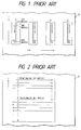
- Conventional plane-scanning type color printing systems will briefly be described hereinbelow with reference to Figs. 1 to 3.
- the plane-scanning type color printer is equipped with four printing heads (yellow, magenta, cyan and black printing heads) illustrated at characters A to D, each of which has N ink-discharging nozzles and is arranged to be mounted on an appropriate carriage, not shown, so as to allow reciprocation.
- a recording sheet illustrated at character P is fed in a direction indicated by an arrow Y and the printing heads A to D are movable in directions (forward and return directions) indicated by an arrow X which is perpendicular to the direction Y.
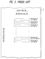
- Each printing head discharges ink in accordance with the movement in the forward direction, i.e., from the left side to the right side in the illustration, so as to color-print N lines as illustrated in Fig. 2.
- the recording sheet is fed by an amount corresponding to the N lines for the return direction color printing.
- the printing head similarly discharges ink in accordance with the movement in the return direction, i.e., from the right side to the left side in the illustration, so as to color-print N lines as illustrated in Fig. 2.
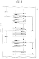
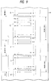
- FIG. 3 another conventional plane-scanning type color printer is similarly equipped with printing heads A to D each of which has N ink-discharging nozzles which are successively arranged at a predetermined interval which is twice the line-printing pitch (half density), where the term "line-printing pitch” refers to the pitch, or distance between, lines to be finally printed by the printing heads for printing images or characters on a surface of a writing sheet.
- line-printing pitch refers to the pitch, or distance between, lines to be finally printed by the printing heads for printing images or characters on a surface of a writing sheet.
- each printing head performs the color-printing at the location of every other line to be printed, i.e., prints at half density, so as to print N (first to Nth) lines.
- the first to Nth lines are printed by the first to Nth ink-discharging nozzles of the printing head so as to leave a separation for printing one line therebetween.
- the recording sheet P is moved by a distance corresponding to one print line and the printing head moves in the returning direction so as to newly color-print N additional lines between the first to Nth lines formed by the going-direction printing due to the same printing head.
- a color printing system for color-printing images or characters on a surface of a writing sheet
- the color printing system comprising: a plurality of printing heads which are successively arranged in parallel to each other and each of which linearly reciprocates bidirectionally so as to go in a forward direction and return in a return direction along the surface of the writing sheet for the color printing, each of the plurality of printing heads having a plurality of ink-discharging nozzles facing the surface of the writing sheet, the plurality of ink-discharging nozzles being successively arranged with a pitch which is equal to or greater than twice the pitch of lines to be finally printed by the plurality of printing heads so as to write the images or characters on the surface of the writing sheet; and writing-sheet feeding means for moving the writing sheet in a direction perpendicular to the forward and return directions, wherein when the printing heads and writing sheet feeding means change performance of a printing operation from the forward direction to the return direction the feeding means operates to move the writing sheet by a distance
- the predetermined number M is set to be substantially equal to the number of nozzles N.
- M is set to be substantially equal to the number of nozzles N, and the feeding means moves the writing sheet by a distance corresponding to N times the line-printing pitch both in changing from the forward direction printing operation to the return direction printing operation and in changing from the return direction printing operation to the forward direction printing operation.
- N is an even number
- M is chosen to equal N + 1 or N - 1.
- the feeding means moves the writing sheet by a distance corresponding to (N + 1) times the line-printing pitch in changing from the return direction printing operation to the forward direction printing operation and moves the sheet by a distance corresponding to (N-1) times the line-printing pitch in turning from the forward direction printing operation to the return direction printing operation.
- the feeding means moves the writing sheet by a distance corresponding to (N - 1) times the line-printing pitch in changing from the return direction printing operation to the forward direction printing operation and moves the sheet by a distance corresponding to (N + 1) times the line-printing pitch in turning from the forward direction printing operation to the return direction printing operation.
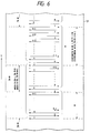
- Fig. 4 is an illustration for describing a reciprocating color printing system according to an embodiment of the present invention.
- the color printing system is provided with yellow, magenta, cyan and black printing heads A to D each of which is mounted on a carriage so as to be movable in directions indicated by an arrow X (horizontal directions in the illustration).
- Each of the printing heads A to D has N ink-discharging nozzles each of which discharges yellow, magenta, cyan or black ink toward a writing sheet by the aid of an electric field established between electrodes, for example.
- the writing sheet illustrated at character P is arranged to be movable in a direction indicated by an arrow Y which is perpendicular to the printing head moving directions X.
- a printing head arrangement in which the printing density is set to be d , the distance between the nozzles is set to be greater than 2/d and the axes of the printing heads are arranged to be inclined with respect to the printing head moving directions so that the distance between the nozzles assumes 2/d, that is, the line pitch assumes 2l. That is, such a printing head arrangement can be employed for this embodiment under the condition that the inclination of each of the printing heads is adapted to be changeable so that the printing density is d/2.
- the printing heads A to D move from the left side to the right side in the illustration in the forward-direction printing operation and, on the other hand, move from the right side to the left side in the return-direction printing operation.
- the first to Nth ink-discharging nozzles (illustrated at 1 to N in the Figure) of each of the printing heads A to D print first to Nth color lines on every other line (with a separation for one print line therebetween) as illustrated in Fig.
- the first color print line formed by the first ink-discharging nozzle 1 thereof is positioned between the print lines due to the [(M+1)/2]th ink-discharging nozzle and the [(M+3)/2]th ink-discharging nozzles in the forward-direction printing operation. Even if the value of M is taken to be 3 which is a minimum value, (M+1)/2 becomes 2.
- the print lines formed by the same ink-discharging nozzle are arranged so as not to be adjacent to each other.
- the recording sheet is moved by a distance corresponding to (2N - M) times the line-printing pitch so that the printing head again performs the forward-direction printing operation for the first to Nth lines which are successively arranged in parallel to each other on every other line.
- the first ink-discharging nozzle 1 of the printing head is positioned between the print lines formed by the [(2N-M+1)/2]th ink-discharging nozzle and the [(2N-M+3)/2]th nozzle.
- the printing head similarly performs the return-direction printing operation.
- the print lines formed by the same ink-discharging nozzle are not adjacent to each other, thereby providing a high-quality color print.
- a second embodiment of this invention will be described hereinbelow with reference to Fig. 6.
- the moved distance of the recording sheet P is set to M times the print line pitch (M is an odd number and determined to be substantially equal to N).
- M is an odd number and determined to be substantially equal to N.
- the necessary capacity of the line buffer memory is as small as possible.
- M is substantially equal to N, not only the memory capacity can be reduced but also the print line due to the first ink-discharging nozzle becomes adjacent to the print line due to the ink-discharging nozzle disposed at the vicinity of the N/2th ink-discharging nozzle, thereby substantially removing the disadvantage resulting from the difference of the ink-discharging amounts between the nozzles.
- the recording sheet P is moved by a distance which is obtained by multiplying the line-printing pitch by a value shown by the following table.
- the print line adjacent to the print line due to the first ink-discharging nozzle is the print line due to the Kth ink-discharging nozzle.
- a line buffer memory for temporarily storing the print signals at every print line is divided in correspondance with N print lines.
- the print signals for the forward-direction printing are stored in the even addresses and the print signals for the return-direction printing are stored in the odd addresses.
- the print signals for the forward-direction printing is also appropriate for the print signals for the forward-direction printing to be stored in the odd addresses and the print signals for the return-direction printing to be stored in the even addresses.
- N is an even number, i.e., 2K
- the print line due to the first ink-discharging nozzle is positioned between the print lines due to the (K+1)th ink-discharging nozzle and the (K+2)th ink-discharging nozzle.
- the print line due to the ink-discharging nozzle disposed at one end of the printing head becomes adjacent to the print line due to the ink-discharging nozzle disposed at the center portion of the printing head, and therefore, it is possible not only to improve the color print quality but also to reduce the number of the line buffer memories.
Landscapes
- Engineering & Computer Science (AREA)
- Quality & Reliability (AREA)
- Ink Jet (AREA)
- Dot-Matrix Printers And Others (AREA)
- Color, Gradation (AREA)
Claims (6)
- Ein Farbdrucksystem zum Farbdrucken von Bildern oder Zeichen auf einer Oberfläche eines Schreibblattes (P), wobei das Farbdrucksystem umfaßt:
eine Mehrzahl von Druckköpfen (A bis D), die aufeinanderfolgend parallel zueinander angeordnet sind, wobei jeder der Mehrzahl von Druckköpfen sich in zwei Richtungen hin- und herbewegt, um sich entlang der Oberfläche des Schreibblattes für den Farbdruck in einer Vorwärtsrichtung zu bewegen und in einer Rückwärtsrichtung zurückzuwegen, wobei jeder der Mehrzahl von Druckköpfen eine Mehrzahl von Tintenausstoßdüsen (N) aufweist, die der Oberfläche des Blattes zugewandt sind, wobei die Mehrzahl von Tintenausstoßdüsen aufeinanderfolgend mit einer Teilung, die gleich oder größer ist als das zweifache einer Teilung von Linien, die schließlich durch die Mehrzahl von Druckköpfen zu drucken sind, um die Bilder oder Zeichen auf die Oberfläche des Schreibblattes zu schreiben, angeordnet sind; und
Schreibblattzuführmittel zum Bewegen des Schreibblattes in einer Richtung senkrecht zu den Vorwärts- und Rückwärtsrichtungen;
dadurch gekennzeichnet, daß
in Verbindung mit einem Wechsel bei der Durchführung eines Druckvorgangs durch die Mehrzahl von Druckköpfen und die Schreibblattzuführmittel von der Vorwärtsrichtung zu der Rückwärtsrichtung das Zuführmittel tätig wird, um das Schreibblatt um eine Strecke, die dem M-fachen der Teilung der Drucklinien entspricht, zu bewegen, wobei M eine vorgegebene ungerade Zahl ist, die sich in einem Bereich von 1 < M < 2N - 1 bewegt, und N die Anzahl der Tintenausstoßdüsen eines jeden der Mehrzahl von Druckköpfen ist, und wobei in Verbindung mit einem Wechsel die Durchführung des Druckvorgangs von einer Rückkehrrichtung zu der Vorwärtsrichtung das Zuführmittel das Schreibblatt um eine Strecke bewegt, die dem 2N-M-fachen der Liniendruckteilung entspricht. - Ein Farbdrucksystem wie in Anspruch 1 beansprucht, worin die vorgegebene Zahl M so festgelegt ist, daß sie im wesentlichen gleich der Anzahl der Düsen N ist, und wenn N eine ungerade Zahl ist, bewegt das Zuführmittel das Schreibblatt um eine Strecke, die dem N-fachen der Liniendruckteilung entspricht, sowohl bei einem Wechsel von dem Druckvorgang in der Vorwärtsrichtung zu dem Druckvorgang in der Rückwärtsrichtung, als auch bei einem Wechsel von dem Druckvorgang in der Rückwärtsrichtung zu dem Druckvorgang in der Vorwärtsrichtung.
- Ein Farbdrucksystem wie in Anspruch 1 beansprucht, worin die vorgegebene Anzahl M so festgelegt ist, daß sie im wesentlichen gleich der Düsenzahl N ist, und wenn N eine gerade Zahl ist, bewegt das Zuführmittel das Schreibblatt um eine Strecke, die dem (N + 1)- oder dem (N - 1)-fachen der Liniendruckteilung entspricht, bei einem Wechsel von dem Druckvorgang in der Rückwärtsrichtung zu dem Druckvorgang in der Vorwärtsrichtung und bewegt entsprechend das Schreibblatt um eine Strecke, die dem (N - 1)- oder dem (N + 1)-fachen der Liniendruckteilung entspricht, bei einem Wechsel von dem Druckvorgang in der Vorwärtsrichtung zu dem Druckvorgang in der Rückwärtsrichtung.
- Ein Verfahren zum Farbdrucken von Bildern oder Zeichen auf einer Oberfläche eines Schreibblattes in einem Farbdrucksystem mit einer Mehrzahl von Druckköpfen (A bis D), die aufeinanderfolgend parallel zueinander angeordnet sind, und wobei jeder der Mehrzahl von Druckköpfen sich in zwei Richtungen linear hin- und herbewegt, um entlang der Oberfläche des Schreibblattes für den Farbdruck in einerVorwärtsrichtung zu laufen und in einer Rückwärtsrichtung zurückzulaufen, wobei jeder der Mehrzahl von Druckköpfen eine Mehrzahl von Tintenausstoßdüsen (N) aufweist, die der Oberfläche des Blattes zugewandt sind, wobei die Mehrzahl von tintenausstoßenden Düsen aufeinanderfolgend mit einer Teilung angeordnet sind, die gleich groß ist wie oder größer ist als das zweifache einer Teilung von Linien, die schließlich durch die Mehrzahl von Druckköpfen zum Schreiben der Bilder oder Zeichen auf der Oberfläche des Schreibblattes gedruckt werden sollen; und Schreibblatt-Zuführmittel zum Bewegen des Schreibblattes in einer Richtung senkrecht zu den Vorwärts- und Rückwärtsrichtungen, dadurch gekennzeichnet, daß es die Schritte aufweist
Bewirken, daß das Zuführmittel das Schreibblatt (P) um eine Strecke, die dem M-fachen der Teilung der gedruckten Linien entspricht, bewegt, nachdem die Mehrzahl von Druckköpfen den Druckvorgang in der Vorwärtsrichtung ausgeführt haben, um das Schreibblatt, das durch eine Bewegung der Mehrzahl von Druckköpfen in der Rückwärtsrichtung bedruckt werden soll, zu positionieren, wobei M eine vorgegebene ungerade Zahl ist, die sich in einem Bereich von 1 < M < 2N - 1 bewegt, und N die Zahl der tintenausstoßenden Düsen eines jeden der Mehrzahl von Druckköpfen ist, und
Bewirken, daß das Zuführmittel das Schreibblatt um eine Strecke bewegt, die dem 2N - M-fachen der Liniendruckteilung entspricht, nachdem die Mehrzahl von Druckköpfen den Druckvorgang in der Rückwärtsrichtung ausgeführt haben, um das Schreibblatt, das durch eine Bewegung der Mehrzahl von Druckköpfen in der Vorwärtsrichtung zu bedrucken ist, zu positionieren. - Das Farbdruckverfahren wie in Anspruch 4 beansprucht, das den weiteren Schritt umfaßt, daß die vorgegebene Anzahl M im wesentlichen gleich der Anzahl der Düsen N festgelegt wird, und daß bewirkt wird, daß das Zuführmittel das Schreibblatt um eine Strecke bewegt, die dem N-fachen der Liniendruckteilung entspricht, und zwar sowohl bei einem Wechsel von dem Druckvorgang in der Vorwärtsrichtung zu einem Druckvorgang in der Rückwärtsrichtung als auch bei einem Wechsel von dem Druckvorgang in der Rückwärtsrichtung zu dem Druckvorgang in der Vorwärtsrichtung, wenn N eine ungerade Zahl ist.
- Das Farbdruckverfahren wie in Anspruch 4 beansprucht, welches den weiteren Schritt aufweist, daß die vorgegebene Anzahl M so festgelegt wird, daß sie im wesentlichen gleich der Anzahl der Düsen N ist, und daß bewirkt wird, daß das Zuführmittel das Schreibblatt um eine Strecke bewegt, die dem (N + 1)- oder (N - 1)-fachen der Liniendruckteilung entspricht, bei einem Wechsel von dem Druckvorgang in der Rückwärtsrichtung zu dem Druckvorgang in der Vorwärtsrichtung, und entsprechend das Schreibblatt um eine Strecke bewegt, die dem (N - 1)- oder (N + 1)-fachen der Liniendruckteilung entspricht, bei einem Wechsel von dem Druckvorgang in der Vorwärtsrichtung zu dem Druckvorgang in der Rückwärtsrichtung, wenn N eine gerade Zahl ist.
Applications Claiming Priority (2)
| Application Number | Priority Date | Filing Date | Title |
|---|---|---|---|
| JP1181042A JP2817224B2 (ja) | 1989-07-13 | 1989-07-13 | カラープリンタ |
| JP181042/89 | 1989-07-13 |
Publications (3)
| Publication Number | Publication Date |
|---|---|
| EP0408071A2 EP0408071A2 (de) | 1991-01-16 |
| EP0408071A3 EP0408071A3 (en) | 1991-10-23 |
| EP0408071B1 true EP0408071B1 (de) | 1994-12-07 |
Family
ID=16093750
Family Applications (1)
| Application Number | Title | Priority Date | Filing Date |
|---|---|---|---|
| EP90113478A Expired - Lifetime EP0408071B1 (de) | 1989-07-13 | 1990-07-13 | Hin- und hergehendes Mehrfarbendrucksystem mit spezifizierter Positionierung von Druckköpfen relativ zu einem Druckbogen |
Country Status (4)
| Country | Link |
|---|---|
| US (1) | US5121142A (de) |
| EP (1) | EP0408071B1 (de) |
| JP (1) | JP2817224B2 (de) |
| DE (1) | DE69014738T2 (de) |
Families Citing this family (16)
| Publication number | Priority date | Publication date | Assignee | Title |
|---|---|---|---|---|
| US6012797A (en) * | 1991-03-29 | 2000-01-11 | Canon Kabushiki Kaisha | Method for driving an ink jet recording head having improved discharge stability and recording apparatus having the same |
| JP3176120B2 (ja) * | 1991-05-27 | 2001-06-11 | キヤノン株式会社 | インクジェット記録装置及びインクジェット記録方法 |
| US5430469A (en) * | 1991-06-05 | 1995-07-04 | Canon Kabushiki Kaisha | Tone recording method using ink recording head |
| WO1993003591A1 (en) * | 1991-07-31 | 1993-02-18 | Cambridge Management Corporation | Close-packed impedance-controlled connectors |
| US5485183A (en) * | 1993-06-30 | 1996-01-16 | Dataproducts Corporation | Interlaced dot-on-dot printing |
| US5790150A (en) * | 1994-02-17 | 1998-08-04 | Colorspan Corporation | Method for controlling an ink jet printer in a multipass printing mode |
| US5686944A (en) * | 1994-03-02 | 1997-11-11 | Seiko Epson Corporation | Serial printer with hybrid print control of interlaced and minute feed printing |
| WO1996014989A2 (en) * | 1994-11-10 | 1996-05-23 | Lasermaster Corporation | Large format ink jet printer and ink supply system |
| US5805183A (en) * | 1994-11-10 | 1998-09-08 | Lasermaster Corporation | Ink jet printer with variable advance interlacing |
| JPH0970959A (ja) * | 1995-09-04 | 1997-03-18 | Canon Inc | 記録装置 |
| JP4193216B2 (ja) | 1997-04-08 | 2008-12-10 | セイコーエプソン株式会社 | ドット記録方法およびドット記録装置 |
| JPH11179890A (ja) | 1997-12-24 | 1999-07-06 | Canon Inc | 記録装置及びその制御方法 |
| US6158841A (en) * | 1998-02-17 | 2000-12-12 | Seiko Epson Corporation | Dot recording with plural nozzle groups |
| JP4566397B2 (ja) * | 2000-11-30 | 2010-10-20 | キヤノン株式会社 | インクジェット記録装置、及びインクジェット記録方法 |
| JP3884993B2 (ja) * | 2001-06-07 | 2007-02-21 | キヤノン株式会社 | 画像記録装置および画像記録方法 |
| JP5031234B2 (ja) * | 2006-01-12 | 2012-09-19 | キヤノン株式会社 | インクジェット記録装置および記録方法 |
Family Cites Families (8)
| Publication number | Priority date | Publication date | Assignee | Title |
|---|---|---|---|---|
| US4063254A (en) * | 1976-06-28 | 1977-12-13 | International Business Machines Corporation | Multiple array printer |
| US4198642A (en) * | 1978-01-09 | 1980-04-15 | The Mead Corporation | Ink jet printer having interlaced print scheme |
| US4232324A (en) * | 1978-06-05 | 1980-11-04 | International Business Machines Corporation | Apparatus for arranging scanning heads for interlacing |
| JPS5693559A (en) * | 1979-12-26 | 1981-07-29 | Ibm | Printer |
| US4401991A (en) * | 1981-10-08 | 1983-08-30 | International Business Machines Corporation | Variable resolution, single array, interlace ink jet printer |
| US4540996A (en) * | 1982-05-11 | 1985-09-10 | Canon Kabushiki Kaisha | Recording apparatus |
| NL8402353A (nl) * | 1984-07-26 | 1986-02-17 | Philips Nv | Werkwijze en drukinrichting voor het lijnsgewijs drukken op een drager van door punt- of lijnvormige elementen samengestelde beelden. |
| US4728968A (en) * | 1985-08-30 | 1988-03-01 | Siemens Aktiengesellschaft | Arrangement of discharge openings in a printhead of a multi-color ink printer |
-
1989
- 1989-07-13 JP JP1181042A patent/JP2817224B2/ja not_active Expired - Lifetime
-
1990
- 1990-07-13 EP EP90113478A patent/EP0408071B1/de not_active Expired - Lifetime
- 1990-07-13 DE DE69014738T patent/DE69014738T2/de not_active Expired - Fee Related
-
1991
- 1991-08-12 US US07/746,082 patent/US5121142A/en not_active Expired - Lifetime
Also Published As
| Publication number | Publication date |
|---|---|
| US5121142A (en) | 1992-06-09 |
| JPH0345350A (ja) | 1991-02-26 |
| DE69014738D1 (de) | 1995-01-19 |
| DE69014738T2 (de) | 1995-04-27 |
| EP0408071A3 (en) | 1991-10-23 |
| EP0408071A2 (de) | 1991-01-16 |
| JP2817224B2 (ja) | 1998-10-30 |
Similar Documents
| Publication | Publication Date | Title |
|---|---|---|
| EP0408071B1 (de) | Hin- und hergehendes Mehrfarbendrucksystem mit spezifizierter Positionierung von Druckköpfen relativ zu einem Druckbogen | |
| US4528576A (en) | Recording apparatus | |
| US4864328A (en) | Dual mode ink jet printer | |
| EP1106369B1 (de) | Kombination von Drucken in ein und zwei Richtungen unter Verwendung verschiedener Tintenarten | |
| US6312102B1 (en) | Color ink jet recording method and apparatus using black ink and color-mixed black ink | |
| JP2731908B2 (ja) | プリンタ駆動方法 | |
| US6663222B2 (en) | Ink jet printer with nozzle arrays that are moveable with respect to each other | |
| US6378982B2 (en) | Printing apparatus and a printing method | |
| EP1288002B1 (de) | Verfahren und Gerät zur Optimierung von diskreten Tropfenvolumen für Mehrfachtropfentintenstrahldrucker | |
| EP1288003A1 (de) | Tintenstrahldrucker mit verbesserter Trocknungszeit | |
| US6402294B2 (en) | Printer, printing method, and data storage medium | |
| US5619233A (en) | Bidirectional ink jet printing with head signature reduction | |
| US6655773B2 (en) | Gray scale pattern and recording method and recording apparatus employing the gray scale pattern | |
| US6142605A (en) | Bidirectional color printing using multipass printmodes with at least partially swath-aligned inkjet printheads | |
| JPS6338309B2 (de) | ||
| EP0836946B1 (de) | Tintenstrahldruckkopf zum Drucken mit hoher Auflösung und Verfahren zum Betrieb desselben | |
| JPS6277951A (ja) | インクジエツト記録方法 | |
| WO2003004274B1 (en) | Method for determining the skew of a printhead of a printed | |
| US6976747B2 (en) | Ink-jet printing apparatus and ink-jet printing method | |
| JPH0377066B2 (de) | ||
| JPH0376226B2 (de) | ||
| JPS5887064A (ja) | 往復ドツト印字位置制御方式 | |
| US7206095B2 (en) | Printing apparatus and method | |
| EP1216838B1 (de) | Tintenstrahldrucker mit relativ zueinander beweglichen Düsenreihen | |
| JPH0376223B2 (de) |
Legal Events
| Date | Code | Title | Description |
|---|---|---|---|
| PUAI | Public reference made under article 153(3) epc to a published international application that has entered the european phase |
Free format text: ORIGINAL CODE: 0009012 |
|
| 17P | Request for examination filed |
Effective date: 19900713 |
|
| AK | Designated contracting states |
Kind code of ref document: A2 Designated state(s): DE FR GB |
|
| PUAL | Search report despatched |
Free format text: ORIGINAL CODE: 0009013 |
|
| AK | Designated contracting states |
Kind code of ref document: A3 Designated state(s): DE FR GB |
|
| 17Q | First examination report despatched |
Effective date: 19930524 |
|
| GRAA | (expected) grant |
Free format text: ORIGINAL CODE: 0009210 |
|
| AK | Designated contracting states |
Kind code of ref document: B1 Designated state(s): DE FR GB |
|
| PG25 | Lapsed in a contracting state [announced via postgrant information from national office to epo] |
Ref country code: FR Effective date: 19941207 |
|
| REF | Corresponds to: |
Ref document number: 69014738 Country of ref document: DE Date of ref document: 19950119 |
|
| EN | Fr: translation not filed | ||
| PLBE | No opposition filed within time limit |
Free format text: ORIGINAL CODE: 0009261 |
|
| STAA | Information on the status of an ep patent application or granted ep patent |
Free format text: STATUS: NO OPPOSITION FILED WITHIN TIME LIMIT |
|
| 26N | No opposition filed | ||
| REG | Reference to a national code |
Ref country code: GB Ref legal event code: IF02 |
|
| PGFP | Annual fee paid to national office [announced via postgrant information from national office to epo] |
Ref country code: DE Payment date: 20050707 Year of fee payment: 16 |
|
| PGFP | Annual fee paid to national office [announced via postgrant information from national office to epo] |
Ref country code: GB Payment date: 20050713 Year of fee payment: 16 |
|
| PG25 | Lapsed in a contracting state [announced via postgrant information from national office to epo] |
Ref country code: GB Free format text: LAPSE BECAUSE OF NON-PAYMENT OF DUE FEES Effective date: 20060713 |
|
| PG25 | Lapsed in a contracting state [announced via postgrant information from national office to epo] |
Ref country code: DE Free format text: LAPSE BECAUSE OF NON-PAYMENT OF DUE FEES Effective date: 20070201 |
|
| GBPC | Gb: european patent ceased through non-payment of renewal fee |
Effective date: 20060713 |