EP0407810A2 - Reinigungsvorrichtung für ein photoempfindliches Element innerhalb eines electrophotographischen Aufzeichnungsgeräts - Google Patents
Reinigungsvorrichtung für ein photoempfindliches Element innerhalb eines electrophotographischen Aufzeichnungsgeräts Download PDFInfo
- Publication number
- EP0407810A2 EP0407810A2 EP90112193A EP90112193A EP0407810A2 EP 0407810 A2 EP0407810 A2 EP 0407810A2 EP 90112193 A EP90112193 A EP 90112193A EP 90112193 A EP90112193 A EP 90112193A EP 0407810 A2 EP0407810 A2 EP 0407810A2
- Authority
- EP
- European Patent Office
- Prior art keywords
- photosensitive member
- toner
- casing
- blade
- recording apparatus
- Prior art date
- Legal status (The legal status is an assumption and is not a legal conclusion. Google has not performed a legal analysis and makes no representation as to the accuracy of the status listed.)
- Ceased
Links
Images


Classifications
-
- G—PHYSICS
- G03—PHOTOGRAPHY; CINEMATOGRAPHY; ANALOGOUS TECHNIQUES USING WAVES OTHER THAN OPTICAL WAVES; ELECTROGRAPHY; HOLOGRAPHY
- G03G—ELECTROGRAPHY; ELECTROPHOTOGRAPHY; MAGNETOGRAPHY
- G03G15/00—Apparatus for electrographic processes using a charge pattern
- G03G15/06—Apparatus for electrographic processes using a charge pattern for developing
- G03G15/08—Apparatus for electrographic processes using a charge pattern for developing using a solid developer, e.g. powder developer
- G03G15/0896—Arrangements or disposition of the complete developer unit or parts thereof not provided for by groups G03G15/08 - G03G15/0894
- G03G15/0898—Arrangements or disposition of the complete developer unit or parts thereof not provided for by groups G03G15/08 - G03G15/0894 for preventing toner scattering during operation, e.g. seals
-
- G—PHYSICS
- G03—PHOTOGRAPHY; CINEMATOGRAPHY; ANALOGOUS TECHNIQUES USING WAVES OTHER THAN OPTICAL WAVES; ELECTROGRAPHY; HOLOGRAPHY
- G03G—ELECTROGRAPHY; ELECTROPHOTOGRAPHY; MAGNETOGRAPHY
- G03G21/00—Arrangements not provided for by groups G03G13/00 - G03G19/00, e.g. cleaning, elimination of residual charge
- G03G21/0005—Arrangements not provided for by groups G03G13/00 - G03G19/00, e.g. cleaning, elimination of residual charge for removing solid developer or debris from the electrographic recording medium
- G03G21/007—Arrangement or disposition of parts of the cleaning unit
Definitions
- This invention relates to a toner seal method and apparatus of a photosensitive member cleaning device disposed inside an electrophotographic recording apparatus.
- a developing device 2 is disposed on the right of a photosensitive member 1 and a photosensitive member cleaning device 3 is disposed on the left.
- a transfer electrode 4 for a recording sheet of paper (hereinafter referred to as "paper") and a separating electrode 5 adjacent to the former are disposed below the photosensitive member 1, so that paper 6 passes above the transfer electrode 4 and the separating electrode 5 while keeping contact tangentially with the photosensitive member 1.
- the photosensitive member 1 is rotated continuously in a direction represented by arrow by a main motor, not shown in the drawing, and is provided with a predetermined potential by a charging electrode 1a.
- a latent image is first formed on the photosensitive member 1 by exposure 15 and when it reaches the position of the developing device 2, a toner 12 inside the developing device attaches to the portion of the latent image due to the electrostatic action with the photosensitive member 1, forming thereby a toner image 16.
- paper 6 is transferred to the lower surface of the photosensitive member 1 by a pair of conveyor rollers 7a disposed on a front transfer table 7 and the toner image 16 is transferred to this paper 6 by the potential of the transfer electrode 4.
- paper 6 is subsequently transferred to a rear transfer table 7b and then to a fixing device 13, where fixing treatment is carried out. Thereafter, paper is discharged outside the electrophotographic recording apparatus and the image recording process is complete.
- the photosensitive member 1 is separated from paper 6 and reaches the cleaning device 3, where the residual toner 12a attaching to the surface and other foreign matters such as paper dust are removed by a blade 3a fitted to the cleaning device 3.
- a recovery casing 9 of the cleaning device 3 is equipped with a toner guide plate 11 made of a PET material and is shaped in a sealed type. Particularly, its blade end portion surface and the portion of the photosensitive member surface of the photosensitive number 1 are provided with a toner seal member in order to prevent invasion and scatter of the residual toner 12a and the paper dust that have been removed, into the electrophotographic recording apparatus.
- the photosensitive member 1 rotates again to the position of the exposure 15 with a predetermined potential and then the first step of image recording is started. In this way, the steps of exposure to the photosensitive member 1, development, transfer, separation, cleaning and fixing of the image to paper 6 are carried out repeatedly and continuously and image recording to paper 6 is effected.
- the photosensitive member cleaning device 3 is one of the important functions of the electrophotographic recording apparatus with the developing device 2 and the fixing device 13.
- the residual toner 12a and the paper dust that attaches to the surface of the photosensitive member 1 are removed and cleaned by the cleaning device 3 after transfer and the exposure 15 is made to this cleaned photosensitive member surface. Accordingly, a clear toner image 16 can be always obtained.
- the residual toner 12a and the paper dust that have thus been removed enter and scatter from the side surface of the blade 3a and near the photosensitive member surface at the end portion of the photosensitive member 1 into the electrophotographic recording apparatus.
- the present invention contemplates to provide a toner seal method and apparatus which can be adapted easily and reliably even to a narrow and complicated surface.
- a toner seal method which is characterized in that a toner seal member for preventing leakage of a residual toner on a photosensitive member surface, which is removed by a blade and stored in a recovery casing, is folded in such a manner as to come into contact with the photosensitive member surface, an end surface of the blade and an end surface of a toner guide plate for the casing which is in parallel with the end surface of the blade, and is bonded to the casing near a photosensitive member, said folding being made in a direction crossing the weaving direction of loops of a velvet woven fabric constituting the seal member.
- a toner seal apparatus which is characterized in that a toner seal member for preventing leakage of a residual toner on a photosensitive member surface which is removed by a blade and stored in a recovery casing is bonded to the casing at its portion near a photosensitive member and an end portion of the blade, said seal member being bonded through a rigid member having a shape that models the casing to be bonded.
- the casing 9 described above has a frame for supporting rotatably the photosensitive member 1 and for holding members such as a blade 3a, a toner transfer screw 10 and a toner guide plate 11, besides its function of storing the residual toner. Therefore, it has a complicated shape having an upper side surface portion, a bottom surface portion, a ridge line and a step portion and its space is extremely limited.
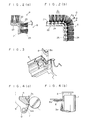
- a toner seal member 8 in accordance with the present invention is made of a flexible fluff-like member such as a felt, a velvet or a woolen cloth and fixed to a rigid support member 8a such as a single metallic plate as shown in Figs. 5 (a) and 5(b).
- This support member 8a is provided with a bent portion A in match with the shape of the casing 9 and a step portion D of a lower surface and is designed so that a surface C and the step portion D serve as bonding reference surfaces.
- a double-face adhesive tape 8b is bonded with an upper sheet 8c to the C surface side of the support member 8a.
- the support member 8a To fit the support member 8a to the casing 9, it can be bonded along the shape of the casing after peeling the upper sheet 8c as shown in Fig. 3.
- a surface portion B of the toner seal member 8 bonded in this manner covers an end surface of the photosensitive member 1 and the bent portion A simultaneously covers end surface portion of the blade 3a and toner guide plate 11 under the state where it comes into light pressure contact with them. Accordingly, it is sealed without applying any trouble to the operation of each of these members. Therefore, the residual toner 12a and paper dust recovered do not leak and scatter outside the casing 9 but are sequentially transferred to a predetermined position by the toner screw 10 through the toner guide plate 11 and are then recovered.
- the fitting reference of the toner seal member 8 is clear and definite. Since it is equipped with the support member made of the stiff material, the toner seal member 8 can be fitted easily and reliably, its fitting does not require any specific skill and fitting variance during mass-production can be eliminated completely.
- the present invention is constituted as described above, fitting of the toner seal member 8 is simple and reliable, the work done factor can be improved remarkably and leakage and scatter of the residual toner 12a and the paper dust into the electrophotographic recording apparatus do not occur. In consequence, contamination of important functional portions does not occur and a quality recorded image can be obtained for an extended period of time. Since the frequency of the cleaning maintenance work due to contamination inside the apparatus can be reduced remarkably, the economical effect is extremely great, too.
- the fluffed woven fabric such as the velvet or the woolen cloth, to which the piles 24 are aligned in the same height and implanted, can be obtained as shown in the front sectional view of Fig. 1(b) or in the side sectional view of Fig. 1(c).
- the piles of this woven fabric are tightly bound by the warps 21 and the wefts 22 or 23 of the woven fabric and do not fall off, but a stitch fixing agent 25 is applied to the bottom portion of the fabric in order to prevent further strongly fall-off.
- the structure of the warps and the wefts is not particularly limited to that of the embodiment described above.
- the fluffed woven fabric it is possible to use a moquette material consisting 100 % of acrylic fibers and having the pile fluff length of 3 to 4 mm.
- the former method the pile density of the fold portions P is close to zero due to the properties of the woven fabric even when the expansion angle ⁇ due to the turn-down of the pile yards is taken into consideration, and the fold portion cannot at all play the role of the seal. Therefore, part of the residual toner 12a which has been scraped off falls down through this fold portion and contaminates the interior of the recording apparatus.
- the pile yard density of the folded portion Q does not much drop due to the expansion of the angle ⁇ in the turn-down direction of the dense pile yarns, and the fall-off of the residual toner 12a does not occur.
- this folding angle is not 90°, it is more preferably at right angles.
- the bonding work of the toner seal member 8 to the limited position of the inner surface of the casing 9 having the complicated shape can be made easily and reliably without any specific skill by merely folding and bonding a single sheet of woven fabric in a predetermined direction but not cutting the woven fabric constituting the seal member into a plurality of pieces and bonding them. Moreover, the trouble of fall of the residual toner 12a into the recording apparatus can be eliminated completely.
- bonding of the seal member 8 to the casing 9 is made by use of an adhesive. It can be made by coating the adhesive to the surface of the stitch fixing agent 25 or by bonding a double-face adhesive tape. Since the toner seal member 8 covers the photosensitive surface portion at the end of the photosensitive member 1 and the end surface portions of the blade 3a and the toner guide plate 11 under the lightly pressure-contact state, these members can be sealed without any trouble in their operations. Accordingly, the residual toner 12a and the paper dust recovered do not leak and scatter outside the casing but are transferred sequentially to the predetermined position by the toner screw 10 through the toner guide plate and recovered there.
- this embodiment has the structure described above, fitting of the toner seal member can be made easily and reliably and the work done factor can be improved remarkably. Since leakage and scatter of the residual toner 12a and the paper dust into the electrophotographic recording apparatus do not occur, contamination of the important functional portions does not occur, either, a quality recorded image can be obtained for a long period and the economical effect is extremely great because the frequency of the cleaning maintenance work can be reduced remarkably.
Landscapes
- Physics & Mathematics (AREA)
- General Physics & Mathematics (AREA)
- Cleaning In Electrography (AREA)
Applications Claiming Priority (2)
| Application Number | Priority Date | Filing Date | Title |
|---|---|---|---|
| JP181308/89 | 1989-07-12 | ||
| JP1181308A JPH0344688A (ja) | 1989-07-12 | 1989-07-12 | トナーシール方法及び装置 |
Publications (2)
| Publication Number | Publication Date |
|---|---|
| EP0407810A2 true EP0407810A2 (de) | 1991-01-16 |
| EP0407810A3 EP0407810A3 (en) | 1992-04-29 |
Family
ID=16098407
Family Applications (1)
| Application Number | Title | Priority Date | Filing Date |
|---|---|---|---|
| EP19900112193 Ceased EP0407810A3 (en) | 1989-07-12 | 1990-06-27 | Toner seal method and apparatus in electrophotographic recording apparatus |
Country Status (3)
| Country | Link |
|---|---|
| US (1) | US5029316A (de) |
| EP (1) | EP0407810A3 (de) |
| JP (1) | JPH0344688A (de) |
Cited By (1)
| Publication number | Priority date | Publication date | Assignee | Title |
|---|---|---|---|---|
| EP1310834A1 (de) * | 2001-11-07 | 2003-05-14 | Toyo Boseki Kabushiki Kaisha | Dichtungselement zur Vermeidung des Entweichens von Micropartikeln |
Families Citing this family (18)
| Publication number | Priority date | Publication date | Assignee | Title |
|---|---|---|---|---|
| EP0530491B1 (de) * | 1991-08-02 | 1997-05-07 | Minolta Co., Ltd. | Elektrofotografisches Bilderzeugungsgerät mit abnehmbarer Bilderzeugerkassette |
| US5216467A (en) * | 1992-01-30 | 1993-06-01 | Xerox Corporation | Brush-based carrier bead removal device for a developer housing in a xerographic apparatus |
| US5303008A (en) * | 1992-06-08 | 1994-04-12 | Eastman Kodak Company | Seal-forming device for a toner receiving aperture |
| EP0585882B1 (de) * | 1992-08-31 | 1997-10-29 | Kabushiki Kaisha Toshiba | In einem elektrophotographischen Gerät verwendeten Entwicklungs- und Reinigungsvorrichtung |
| US5475467A (en) * | 1993-04-19 | 1995-12-12 | Canon Kabushiki Kaisha | Sealing member, and process cartridge and image forming apparatus using same |
| JP3605203B2 (ja) * | 1995-11-10 | 2004-12-22 | コニカミノルタビジネステクノロジーズ株式会社 | 画像形成装置 |
| JP3554164B2 (ja) * | 1997-11-07 | 2004-08-18 | キヤノン株式会社 | プロセスカートリッジ、電子写真画像形成装置及びシール部材 |
| JP2000075650A (ja) * | 1998-08-31 | 2000-03-14 | Canon Inc | 現像剤シール部材、現像ユニット、プロセスカートリッジ及び画像形成装置 |
| US6487383B2 (en) | 2001-04-12 | 2002-11-26 | Lexmark International, Inc. | Dynamic end-seal for toner development unit |
| JP3611811B2 (ja) * | 2001-08-22 | 2005-01-19 | ティー・アンド・エム株式会社 | 高速回転体用シール材およびその使用方法ならびに現像装置 |
| US6553195B2 (en) | 2001-09-27 | 2003-04-22 | Kurt Matthew Korfhage | Dynamic end seal for image forming apparatus |
| US6744999B2 (en) * | 2002-06-24 | 2004-06-01 | Xerox Corporation | Blade seal for a xerographic module |
| JP2005134844A (ja) * | 2003-10-31 | 2005-05-26 | Canon Inc | シール部材、現像装置、プロセスカートリッジ、及び画像形成装置 |
| US7627264B2 (en) * | 2005-09-30 | 2009-12-01 | Brother Kogyo Kabushiki Kaisha | Developing device and image forming apparatus |
| US7623807B2 (en) * | 2005-12-15 | 2009-11-24 | Lexmark International, Inc. | Dynamic seal for component surfaces |
| US8099012B2 (en) * | 2007-12-18 | 2012-01-17 | Lexmark International, Inc. | Developer roll lip seal |
| US8116657B2 (en) * | 2007-12-18 | 2012-02-14 | Lexmark International, Inc. | Upper seal for inhibiting doctor blade toner leakage |
| US8644725B2 (en) | 2011-05-18 | 2014-02-04 | Lexmark International, Inc. | Multiple stiffness seal for imaging component surfaces |
Family Cites Families (5)
| Publication number | Priority date | Publication date | Assignee | Title |
|---|---|---|---|---|
| US3809012A (en) * | 1972-11-24 | 1974-05-07 | Xerox Corp | Developer seal |
| JPS5749978A (en) * | 1980-09-10 | 1982-03-24 | Konishiroku Photo Ind Co Ltd | Cleaning device of recorder |
| US4564283A (en) * | 1984-06-22 | 1986-01-14 | Xerox Corporation | Blade cleaner apparatus for removing toner from a charge-retentive surface |
| US4681426A (en) * | 1986-05-19 | 1987-07-21 | Xerox Corporation | Brush end seals for blade cleaner housing |
| JPH0622862Y2 (ja) * | 1986-09-22 | 1994-06-15 | 三田工業株式会社 | 電子写真複写機のクリ−ニング装置 |
-
1989
- 1989-07-12 JP JP1181308A patent/JPH0344688A/ja active Pending
-
1990
- 1990-06-27 EP EP19900112193 patent/EP0407810A3/en not_active Ceased
- 1990-06-29 US US07/545,839 patent/US5029316A/en not_active Expired - Fee Related
Cited By (3)
| Publication number | Priority date | Publication date | Assignee | Title |
|---|---|---|---|---|
| EP1310834A1 (de) * | 2001-11-07 | 2003-05-14 | Toyo Boseki Kabushiki Kaisha | Dichtungselement zur Vermeidung des Entweichens von Micropartikeln |
| US6681086B2 (en) | 2001-11-07 | 2004-01-20 | Toyo Boseki Kabushiki Kaisha | Sealing member for preventing escape of micro particles |
| CN100362436C (zh) * | 2001-11-07 | 2008-01-16 | 东洋纺织株式会社 | 防止微细粉粒体泄漏的密封材料 |
Also Published As
| Publication number | Publication date |
|---|---|
| US5029316A (en) | 1991-07-02 |
| JPH0344688A (ja) | 1991-02-26 |
| EP0407810A3 (en) | 1992-04-29 |
Similar Documents
| Publication | Publication Date | Title |
|---|---|---|
| US5029316A (en) | Toner seal method and apparatus in electrophotographic recording apparatus | |
| CN101639648B (zh) | 显影装置和电子照相成像装置 | |
| EP0563560B1 (de) | Bilderzeugungsgerät | |
| US4681426A (en) | Brush end seals for blade cleaner housing | |
| US5444522A (en) | Replaceable cleaner subsystem that prevents particle spillage | |
| JP3255339B2 (ja) | 画像形成装置 | |
| EP0272486B1 (de) | Reinigungsvorrichtung für ein Bilderzeugungsgerät | |
| JPS6114679A (ja) | 残留トナー除去用クリーニング装置及びこれを用いた複写装置 | |
| JP3967001B2 (ja) | トナーを用いる電子写真装置用のトナーの漏れを防止するためのシール材及びその製造方法 | |
| US6760554B2 (en) | Drop seal actuator | |
| JP2669471B2 (ja) | キャリヤ粒子除去装置を備えた複写機 | |
| JP3384721B2 (ja) | 作像ユニット | |
| US5450186A (en) | Retractable flexible cleaner brush | |
| JPH06503659A (ja) | 静電写真複写装置のための改善したクリーニング組立体 | |
| US5034779A (en) | Fibre traps in electrostatographic machines | |
| US4516850A (en) | Toner cleaning device for electrophotographic copying machine | |
| JPH0990694A (ja) | クリーニング装置及びプロセスカートリッジ | |
| US5235390A (en) | Developing device with toner cartridge cover shaped to prevent leakage | |
| JPS62278575A (ja) | 画像生成機 | |
| US5241352A (en) | Air detoned cleaner brush | |
| JP3292586B2 (ja) | 画像形成装置 | |
| CA2036828C (en) | Developing device | |
| JPH01142666A (ja) | 画像形成装置 | |
| US5937251A (en) | Developing device and image forming apparatus | |
| CA1120090A (en) | Electrostatic copying process and apparatus |
Legal Events
| Date | Code | Title | Description |
|---|---|---|---|
| PUAI | Public reference made under article 153(3) epc to a published international application that has entered the european phase |
Free format text: ORIGINAL CODE: 0009012 |
|
| AK | Designated contracting states |
Kind code of ref document: A2 Designated state(s): DE FR GB |
|
| PUAL | Search report despatched |
Free format text: ORIGINAL CODE: 0009013 |
|
| AK | Designated contracting states |
Kind code of ref document: A3 Designated state(s): DE FR GB |
|
| 17P | Request for examination filed |
Effective date: 19921001 |
|
| 17Q | First examination report despatched |
Effective date: 19930312 |
|
| STAA | Information on the status of an ep patent application or granted ep patent |
Free format text: STATUS: THE APPLICATION HAS BEEN REFUSED |
|
| 18R | Application refused |
Effective date: 19940407 |