EP0407654A2 - Appareil d'indication et procédé pour la détermination de la position absolute d'une aiquille dans l'appareil - Google Patents
Appareil d'indication et procédé pour la détermination de la position absolute d'une aiquille dans l'appareil Download PDFInfo
- Publication number
- EP0407654A2 EP0407654A2 EP89119662A EP89119662A EP0407654A2 EP 0407654 A2 EP0407654 A2 EP 0407654A2 EP 89119662 A EP89119662 A EP 89119662A EP 89119662 A EP89119662 A EP 89119662A EP 0407654 A2 EP0407654 A2 EP 0407654A2
- Authority
- EP
- European Patent Office
- Prior art keywords
- rotating field
- pointer
- rotor
- signal
- display device
- Prior art date
- Legal status (The legal status is an assumption and is not a legal conclusion. Google has not performed a legal analysis and makes no representation as to the accuracy of the status listed.)
- Granted
Links
Images

Classifications
-
- G—PHYSICS
- G01—MEASURING; TESTING
- G01D—MEASURING NOT SPECIALLY ADAPTED FOR A SPECIFIC VARIABLE; ARRANGEMENTS FOR MEASURING TWO OR MORE VARIABLES NOT COVERED IN A SINGLE OTHER SUBCLASS; TARIFF METERING APPARATUS; MEASURING OR TESTING NOT OTHERWISE PROVIDED FOR
- G01D5/00—Mechanical means for transferring the output of a sensing member; Means for converting the output of a sensing member to another variable where the form or nature of the sensing member does not constrain the means for converting; Transducers not specially adapted for a specific variable
- G01D5/12—Mechanical means for transferring the output of a sensing member; Means for converting the output of a sensing member to another variable where the form or nature of the sensing member does not constrain the means for converting; Transducers not specially adapted for a specific variable using electric or magnetic means
- G01D5/14—Mechanical means for transferring the output of a sensing member; Means for converting the output of a sensing member to another variable where the form or nature of the sensing member does not constrain the means for converting; Transducers not specially adapted for a specific variable using electric or magnetic means influencing the magnitude of a current or voltage
- G01D5/20—Mechanical means for transferring the output of a sensing member; Means for converting the output of a sensing member to another variable where the form or nature of the sensing member does not constrain the means for converting; Transducers not specially adapted for a specific variable using electric or magnetic means influencing the magnitude of a current or voltage by varying inductance, e.g. by a movable armature
- G01D5/22—Mechanical means for transferring the output of a sensing member; Means for converting the output of a sensing member to another variable where the form or nature of the sensing member does not constrain the means for converting; Transducers not specially adapted for a specific variable using electric or magnetic means influencing the magnitude of a current or voltage by varying inductance, e.g. by a movable armature differentially influencing two coils
- G01D5/2208—Mechanical means for transferring the output of a sensing member; Means for converting the output of a sensing member to another variable where the form or nature of the sensing member does not constrain the means for converting; Transducers not specially adapted for a specific variable using electric or magnetic means influencing the magnitude of a current or voltage by varying inductance, e.g. by a movable armature differentially influencing two coils by influencing the self-induction of the coils
- G01D5/2216—Mechanical means for transferring the output of a sensing member; Means for converting the output of a sensing member to another variable where the form or nature of the sensing member does not constrain the means for converting; Transducers not specially adapted for a specific variable using electric or magnetic means influencing the magnitude of a current or voltage by varying inductance, e.g. by a movable armature differentially influencing two coils by influencing the self-induction of the coils by a movable ferromagnetic element, e.g. a core
Definitions
- the invention relates to a method for determining the absolute position of a pointer in a display device which is moved by a rotor of a rotating field motor via a gear, and a display device with a pointer which is moved by a rotor from a rotor of a rotating field motor and with a stop for the pointer, the rotating field motor having at least two field-generating coils, which are electrically connected to a control device that generates a signal at the output for each coil.
- a large number of positions of the pointer are assigned to each angular position of the rotor in the motor.
- the absolute position of the pointer can therefore no longer be determined from the motor data alone. This is particularly disadvantageous if the energy supply to the actuating system is interrupted for some reason and the actuating system loses the information about the current pointer position. This can be the case in particular when using the display device mentioned at the beginning in motor vehicles, where, for example, the electrical connection to the battery must be completely interrupted for safety reasons when repairs are being carried out to the electrical equipment.
- the use of external sensors for example inductive proximity switches, mechanical limit switches, light barriers or the like, makes the display device more expensive. In addition, more components automatically mean a greater weight, which is particularly undesirable when used in motor vehicle or aircraft technology. In addition, there is often not enough space to accommodate the external sensors.
- This object is achieved in a method of the type mentioned above in that the pointer is moved by a rotating field in the rotating field motor in a predetermined rotating field direction against a stop, the rotating field is rotated further in the rotating field direction, one by moving the rotor against the rotating field -Direction in the field-generating part of the rotating field motor induced signal is detected and the angular position of the rotor is determined from the angular position of the rotating field when the induced signal occurs, at which the pointer rests on the stop.
- the invention is based on the following principle: If the rotor of a rotating field motor can no longer rotate because its output is blocked, for example because the pointer is against a stop at the output of the transmission, and the driving field continues to move, the rotor rotates against the actual direction of rotation of the field if the angle difference between the main axis of the rotor, which is usually formed by a magnet, and the main axis of the field is greater than 180 °. In this case, the rotor "tilts" from an unstable equilibrium, which occurs at an angle difference of exactly 180 °, into a stable equilibrium, which prevails at an angle difference of 0 °. The two main axes of the rotor and the rotating field are again aligned.
- the movement of the rotor induces a signal in the coil arrangement that generates the rotating field.
- This signal can occur, for example, as a voltage that is opposite to the voltage that generated it.
- This signal can then be evaluated. Since the angular position of the rotating field ah at the time at which the signal occurs is known, the stop position of the pointer can be calculated by subtracting 180 ° from this angular position.
- the rotating field can be rotated continuously. For a better resolution, however, it is advantageous that the rotating field is rotated step by step.
- the signal that is induced by the rotating rotor then appears after a certain step. Since the angular increment covered by the pointer is known for each step, the subtraction of the 180 ° can be carried out very simply by recalculating a certain number of steps.
- a pause of a preselectable length is provided between each step.
- the rotor naturally takes a certain amount of time to turn back. This time is determined, among other things, by the inertia that the rotor opposes to its rotation. If there is a pause after each step, the rotor has enough time to turn back and align with the field. If the pauses are sufficiently dimensioned, it cannot occur that the signal indicating that the rotor is rotating back only occurs when the rotating field has already rotated too far, i.e. by an angle of far more than 180 °.
- the rotation of the rotating field is advantageously continued after the occurrence of the induced signal, and only a second or later induced signal is used to determine the absolute position of the pointer. If the system is started from any state, the relationship of the magnetic field to the angular position of the rotor is not defined. However, the magnetic field of the rotary field motor must be switched on in a certain position. This forced setting of an angle can result in an output signal in the coil arrangement, if, for example, the angular position of the rotor did not match the angular position of the field. To ensure that this signal is not mistakenly evaluated for determining the stop state of the pointer, the invention provides that only the second or a later signal is used to determine whether the rotor is at the stop or not.
- the proposed procedure does no harm.
- the rotor is then moved against the stop, and generates a first signal after rotation of the rotating field by a little more than 180 °, which could theoretically be used to determine the stop position of the pointer.
- the rotor then continues to rotate, the stop position of the pointer actually being determined only at the second rotation, because only the second pulse is "valid".
- the low mechanical load on the pointer is irrelevant.
- the invention provides that the angular position of the rotating field at which the signal is induced is determined and stored in a non-volatile manner in a learning phase, and that this angular position of the rotating field is set at the start of a determination phase.
- the learning phase the pointer is slowly moved twice against the stop, the real zero point, ie the angular position of the rotating field at which the pointer lies against the stop, is calculated and this value is stored, for example in a non-volatile memory (EEPROM).
- EEPROM non-volatile memory
- the object is achieved in that an evaluation circuit is provided which compares the signals at the output of the control device with the signals at the input of the associated coil.
- the signals at the output of the control device generate a magnetic field in each coil.
- the superimposition of the magnetic fields of each coil results in the resulting magnetic field.
- the direction of the resulting magnetic field can be changed by changing the current conditions in the individual coils.
- a rotating field can be generated in that the control device generates a sinusoidal output signal for each coil, the output signals being electrically out of phase with one another by an angle which corresponds to the spatial angle between the individual coils of the coil arrangement.
- the sinusoidal signals can of course also be constructed in steps or steps if the rotor of the rotating field motor moves step by step.
- the evaluation device now examines whether the signal curve at the input of the respective coils (input signals) corresponds to the output signals of the control device. This will always be the case, except when the rotor turns back to align with the field. In this case, the output signal of the control device no longer corresponds to the input signal of the associated coil.
- the evaluation circuit can then generate a signal that indicates this mismatch.
- the evaluation circuit advantageously has a subtractor for each coil, which forms the difference between a voltage across the coil and a voltage at the associated output of the control device.
- This difference normally follows a certain law. If both voltages have a sinusoidal shape with different amplitudes, the differential voltage is also sinusoidal, the amplitude corresponding to the amplitude difference. However, this regularity is disturbed when the rotor turns back and induces an additional voltage in the coil.
- a scaling device which makes the amplitude of the two input voltages of each subtractor the same size. The difference that the subtractor generates then normally becomes zero. Only when the rotor turns back and induces a voltage does a non-zero voltage appear at the output of the subtractor.
- Each scaling device preferably has two voltage dividers.
- the scaling device can be implemented in a simple manner with these voltage dividers.
- One of the two voltage dividers can have the associated coil and an ohmic resistor and the other voltage divider can have two ohmic resistors.
- the voltage division using an ohmic or an ohmic-inductive voltage divider is a simple method for scaling the tapped voltages.
- the outputs of the subtractors are connected to a logic circuit, which generates an output signal when the signal of at least one subtractor output exceeds a predetermined value.
- the output of the subtractor is usually zero. Only when a signal occurs because the rotor turns back does the voltage across the coil deviate from the voltage at the output of the control device. In this case, the subtractor produces an output signal. If several coils are present, as is the case with a rotating field motor, it can happen that no signal or only a very small, barely measurable signal is not generated in one of the coils. In order to ensure that the evaluation device reliably detects a signal, the logic circuit is provided which already reacts when only a signal is induced in one coil.
- the control device advantageously has a digitally operating signal generator.
- the control device can therefore very easily generate a step-like output voltage.
- a rotating field motor 1 has a rotor 2 which carries a magnet 3.
- the magnet 3 is usually a permanent magnet, but it can also be designed as an electromagnet.
- the rotor 2 of the rotary field motor 1 is connected to a gear 31 via an axis 32.
- a pointer 33 is arranged, which is movable over a scale 34.
- a stop 24 which marks the zero point or another excellent position of the pointer. If the pointer 33 is moved against the stop 24, any movement of the rotor 2 in the same direction is blocked via the gear 31 and the axis 32.
- the motor 1 has two coils 4, 5, the coil axes of which are spatially offset from one another by 90 °.
- a control device 6 generates a voltage for each coil 4, 5, which are supplied to the coil 4 via a line pair 7 and the coil 5 via a line pair 8.
- the control device 6 has a signal generator 9, the signals of which are amplified in an amplifier 10 by driver stages 11.
- the signal generator 9 is a digital signal generator, ie it generates a sequence of predetermined voltage levels for each coil. The voltage difference from level to level can vary. For example, one can strive to achieve a sinusoidal voltage profile.
- the output signals of the signal generator 9 are filtered in a low-pass filter 18. A more or less sinusoidal voltage can therefore be tapped at the output of the control device 6.
- the control device 6 has a control logic 12 which controls the signal generator 9.
- the control logic 12 can be implemented with the aid of a microprocessor, for example.
- a rotating magnetic field is generated in the rotating field motor 1 by different energization of the two coils 4, 5.
- This magnetic field results from the superposition of the magnetic field generated by the coil 4 with the magnetic field generated by the coil 5.
- the direction of the magnetic field depends essentially on the ratio of the current supply to the two coils 4, 5.
- a field can be generated in the rotating field motor 1, which, for example, counteracts the Rotates clockwise, as shown in Fig. 2.
- an energization ratio and thus a magnetic field direction are arbitrarily set. For example, only the coil 4 receives a current, while the coil 5 remains de-energized.
- the resulting magnetic field is represented by arrow 19.
- the angular position of the magnet 3 and the rotor 2 will usually not match.
- the rotor 2 will therefore rotate in the direction of the arrow 20 so that the main direction, ie the north-south axis, of the magnet 3 coincides with the main direction 19 of the magnetic field.
- the magnetic field then rotates further in the direction of arrow 21, the magnet 3 running in the direction of arrow 21 '.
- a certain angular difference can occur between the magnetic field 19 and the magnet 3 (FIG. 2c).
- the pointer 33 runs against a stop 24, so that a further movement of the rotor 2 is blocked, as is shown schematically in FIG. 2d .
- the magnetic field 19 continues to rotate in the direction of the arrow 22.
- the magnetic field rotates through an angle of 180 ° has, the polarities of magnetic field 19 and magnet 3 are exactly opposite.
- the magnet 3 is in an unstable equilibrium state. If the magnetic field 19 is now rotated further by a small angle in the original direction, the magnet 3 “tilts” and rotates backwards in the opposite direction to the magnetic field 19 in order to align itself with the magnetic field 19 again (FIG. 2e).
- the magnet 3 induces a voltage in the two coils 4, 5 which is opposite to the supply voltage.
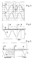
- 3 shows the output voltage of the control device 6 as the supply voltage 25.
- a voltage 26 is tapped via the coil 5. At the moment when the magnet 3 turns back against the normal direction of field rotation, it induces a signal 27.
- the evaluation device 14 has a subtractor 15, 16 for each coil 4, 5, the outputs of which are connected to an OR circuit 17.
- the inputs of the two subtractors are each supplied with voltages which have been scaled via a scaling device 13 such that the maximum values of the amplitudes of the vibrations supplied to the two inputs of the subtractors 15, 16 are the same.
- the scaling device has a bridge circuit for each coil 4, 5, one branch of which has a voltage divider with two ohmic resistors 41, 42 and 44, 45, while the other branch has an ohmic-inductive voltage divider consisting of coil 4 and ohmic resistor 43 or the coil 5 and the ohmic resistor 46.
- the voltage dividers and thus the bridge can be dimensioned such that, in the normal case, ie when the magnet 3 follows the field 19 unhindered, the same voltage drops across the coil 4 as across the ohmic resistor 42 or across the coil 5, the same voltage as across the resistor 45.
- the output of the subtractors 15, 16 is therefore approximately zero as a rule. This is shown in FIG. 4 using curve 28, which represents the output signal of subtractor 14. Only in the case where the rotor 2 turns back after the field has traveled 180 ° is a voltage induced in the coils 4, 5, which causes the voltage across the coils 4, 5 from the voltages across the resistors 41 , 44 deviates. A voltage pulse 29 is generated.
- This voltage pulse is greater than a predetermined limit value 35.
- a logic circuit 17 always generates a signal at its output when at least one of the subtractors 15, 16 generates a signal at its output that exceeds the threshold value 35. This ensures that every movement of the rotor 2 is recognized, even if a sufficiently large voltage is induced in only one of the two coils due to unfavorable geometric conditions.
- the logic circuit 17, which is therefore essentially constructed as an OR gate, supplies an output signal to the control logic 12. If the control logic 12 is implemented with the aid of a microprocessor, the output signal of the logic circuit 17 can be passed, for example, to an interrupt input of the microprocessor .
- the procedure of the display device is described with reference to FIG. 4.
- the signal generator 9 generates for each coil 4, 5 a step-shaped output signal 25 which, apart from the steps, is essentially sinusoidal. There is a short pause after each voltage change.
- the voltages for the two coils 4, 5 are 90 ° out of phase with one another.
- the rotor 2 can no longer turn.
- the field generated by the coils 4, 5 continues to rotate.
- the rotor 2 turns back against the direction of rotation of the field. Its magnet 3 induces a voltage.
- One of the two subtractors 15, 16 therefore generates an output signal 29.
- this output signal 29 is due to the fact that the rotor has rotated through 180 ° after reaching the stop (FIG. 2e) or whether it is only rotating has aligned with the field, which can happen when the arrangement is switched on (FIG. 2b), a further rotation of the field is carried out for safety reasons.
- the pointer then runs against the stop again and blocks the further rotation of the rotor. Only after the field has been rotated by a further 180 ° does the rotor jump back and generate a further pulse 30. 180 ° later in the voltage curve 25 is exactly the point in time at which the pointer 33 came to rest against the stop 24.
- a so-called learning phase is provided so that when a pulse occurs it can be said with certainty whether this pulse can be used to determine the absolute relationship between the pointer stop position and the position of the rotor in the motor .
- the rotor is moved in the learning phase so that the pointer is slowly moved twice against the stop.
- the real zero point ie the time in the course of the supply voltage or the electrical angle at which the pointer 33 is moved to the stop 24, is calculated and this zero point is stored in a non-volatile memory, for example an EEPROM.
- the zero point is different for each display device. Once the zero point has been determined, you can always use a correct zero point when starting. When starting, the exact current is set which has been determined to belong to the zero point. If the rotor now moves, you know that this signal is an error signal and can be ignored. This error signal is shown in FIG. 5 as signal 29. Only when the actual signal 30 occurs does one know that the pointer is in the stop position. The control logic 12 now waits a predetermined time before starting the actual display when the signal generator 9 is triggered again.
- the control voltage 25 of the control device 6 is built up in a step-like manner, a certain time passing between each individual step in which the current ratio of the coils 4, 5 is not changed. This time is sufficient to enable the rotor to reverse when the field has rotated more than 180 ° since the pointer was brought up to the stop.
- the control device 6 sets the magnetic field in the rotary field motor 1 to a new angle and waits for a certain time.
- the subtractors 15, 16 are then used to check whether a voltage spike 29, 30 has occurred. If this is not the case, a new angle is set. If this is the case, the motor was at the stop.
- the return phase is now complete.
- the absolute reference point has been established and a desired position can now be approached. The ad can start operating normally.
Landscapes
- Physics & Mathematics (AREA)
- General Physics & Mathematics (AREA)
- Control Of Stepping Motors (AREA)
- Indicating Measured Values (AREA)
- Arrangements For Transmission Of Measured Signals (AREA)
Applications Claiming Priority (2)
| Application Number | Priority Date | Filing Date | Title |
|---|---|---|---|
| DE3919926 | 1989-06-19 | ||
| DE3919926A DE3919926A1 (de) | 1989-06-19 | 1989-06-19 | Verfahren zum bestimmen der absoluten position eines zeigers in einer anzeigeeinrichtung und anzeigeeinrichtung |
Publications (3)
| Publication Number | Publication Date |
|---|---|
| EP0407654A2 true EP0407654A2 (fr) | 1991-01-16 |
| EP0407654A3 EP0407654A3 (en) | 1993-08-04 |
| EP0407654B1 EP0407654B1 (fr) | 1995-02-22 |
Family
ID=6383015
Family Applications (1)
| Application Number | Title | Priority Date | Filing Date |
|---|---|---|---|
| EP89119662A Expired - Lifetime EP0407654B1 (fr) | 1989-06-19 | 1989-10-24 | Appareil d'indication et procédé pour la détermination de la position absolute d'une aiquille dans l'appareil |
Country Status (4)
| Country | Link |
|---|---|
| US (1) | US5055782A (fr) |
| EP (1) | EP0407654B1 (fr) |
| JP (1) | JPH0690054B2 (fr) |
| DE (2) | DE3919926A1 (fr) |
Families Citing this family (7)
| Publication number | Priority date | Publication date | Assignee | Title |
|---|---|---|---|---|
| DE4200551A1 (de) * | 1992-01-11 | 1993-07-15 | Vdo Schindling | Synchronisierverfahren fuer ein anzeigegeraet mit elektrisch angesteuertem schrittmotor |
| DE4423119C1 (de) * | 1994-07-01 | 1995-12-14 | Moto Meter Gmbh | Verfahren zur Nullpositionierung eines Zeigers |
| WO1999011999A1 (fr) * | 1996-03-05 | 1999-03-11 | Harri Saario | Procede et appareil de mesure d'un mouvement de rotation |
| JP4509332B2 (ja) * | 2000-08-09 | 2010-07-21 | 矢崎総業株式会社 | ステッパモータ駆動回路 |
| JP4718150B2 (ja) * | 2003-10-29 | 2011-07-06 | カルソニックカンセイ株式会社 | 指示計器 |
| DE102005021350A1 (de) * | 2005-05-04 | 2006-12-28 | Prefag Carl Rivoir GmbH & Co. Fabrik f. Präzisionsteile KG | Meßwerk |
| DE102009056259B4 (de) * | 2009-11-28 | 2019-05-16 | Festo Ag & Co. Kg | Messanordnung |
Citations (5)
| Publication number | Priority date | Publication date | Assignee | Title |
|---|---|---|---|---|
| DE2527744A1 (de) * | 1974-06-24 | 1976-01-15 | Gen Electric | Elektronisch kommutierter motor und verfahren zu seiner herstellung |
| DE2946328A1 (de) * | 1978-11-21 | 1980-05-22 | Berney Sa Jean Claude | Analoge anzeigevorrichtung |
| DE3306642A1 (de) * | 1983-02-25 | 1984-09-13 | Licentia Patent-Verwaltungs-Gmbh, 6000 Frankfurt | Verfahren zur fortschaltung des staenderdrehfeldes einer synchronmaschine |
| JPS60152298A (ja) * | 1984-01-18 | 1985-08-10 | Hitachi Ltd | ステツプモ−タの回転検出装置 |
| JPH1126506A (ja) * | 1997-06-30 | 1999-01-29 | Nec Kansai Ltd | 半導体装置及びその製造方法 |
Family Cites Families (3)
| Publication number | Priority date | Publication date | Assignee | Title |
|---|---|---|---|---|
| US3998179A (en) * | 1973-12-17 | 1976-12-21 | Dover Corporation | Apparatus for operating a pressure gauge or the like |
| US3977248A (en) * | 1975-04-03 | 1976-08-31 | Fischer & Porter Co. | Linearizing elements for variable area flowmeter |
| JPS5886405A (ja) * | 1981-11-18 | 1983-05-24 | Nec Corp | 角度検出器 |
-
1989
- 1989-06-19 DE DE3919926A patent/DE3919926A1/de not_active Withdrawn
- 1989-10-24 EP EP89119662A patent/EP0407654B1/fr not_active Expired - Lifetime
- 1989-10-24 DE DE58909039T patent/DE58909039D1/de not_active Expired - Lifetime
-
1990
- 1990-05-31 US US07/531,034 patent/US5055782A/en not_active Expired - Lifetime
- 1990-06-18 JP JP2157797A patent/JPH0690054B2/ja not_active Expired - Lifetime
Patent Citations (5)
| Publication number | Priority date | Publication date | Assignee | Title |
|---|---|---|---|---|
| DE2527744A1 (de) * | 1974-06-24 | 1976-01-15 | Gen Electric | Elektronisch kommutierter motor und verfahren zu seiner herstellung |
| DE2946328A1 (de) * | 1978-11-21 | 1980-05-22 | Berney Sa Jean Claude | Analoge anzeigevorrichtung |
| DE3306642A1 (de) * | 1983-02-25 | 1984-09-13 | Licentia Patent-Verwaltungs-Gmbh, 6000 Frankfurt | Verfahren zur fortschaltung des staenderdrehfeldes einer synchronmaschine |
| JPS60152298A (ja) * | 1984-01-18 | 1985-08-10 | Hitachi Ltd | ステツプモ−タの回転検出装置 |
| JPH1126506A (ja) * | 1997-06-30 | 1999-01-29 | Nec Kansai Ltd | 半導体装置及びその製造方法 |
Non-Patent Citations (2)
| Title |
|---|
| PATENT ABSTRACTS OF JAPAN vol. 009, no. 321 (E-367)17 December 1985 & JP-A-60 152 298 ( HITACHI SEISAKUSHO KK ) 10 August 1985 * |
| PATENT ABSTRACTS OF JAPAN vol. 013, no. 370 (P-920)17 August 1989 & JP-A-11 26 506 ( SEIKO ELECTRONIC COMPONENTS ) 18 May 1989 * |
Also Published As
| Publication number | Publication date |
|---|---|
| EP0407654A3 (en) | 1993-08-04 |
| DE3919926A1 (de) | 1990-12-20 |
| DE58909039D1 (de) | 1995-03-30 |
| US5055782A (en) | 1991-10-08 |
| JPH0690054B2 (ja) | 1994-11-14 |
| EP0407654B1 (fr) | 1995-02-22 |
| JPH0331722A (ja) | 1991-02-12 |
Similar Documents
| Publication | Publication Date | Title |
|---|---|---|
| DE102015121717B4 (de) | Elektrisches Servolenksystem für ein Fahrzeug | |
| EP1397277B8 (fr) | Systeme de blocage de direction electrique | |
| DE3604396C2 (fr) | ||
| DE3019903C2 (fr) | ||
| EP1615332B1 (fr) | Procédé de fonctionnement d'un moteur à commutation électronique | |
| EP0582111B1 (fr) | Capteur inductif de position | |
| EP0014241B1 (fr) | Procédé pour l'asservissement d'un mécanisme à moteur à courant continu vers un point de destination et un circuit pour la mise en oeuvre de ce procédé | |
| DE112005001683T5 (de) | Motorsteuereinrichtung | |
| DE2612356A1 (de) | Antiblockierregler fuer kraftfahrzeuge | |
| DE102013218041A1 (de) | Verfahren zum Betreiben eines Elektromotors | |
| WO2001077693A1 (fr) | Dispositif pour identifier la position et/ou la vitesse de rotation et/ou le sens de rotation d'une piece rotative | |
| EP0407654B1 (fr) | Appareil d'indication et procédé pour la détermination de la position absolute d'une aiquille dans l'appareil | |
| DE19511865C1 (de) | Einrichtung zum Antrieb eines Stellelements mittels eines Schrittmotors | |
| DE19612597A1 (de) | Anschlags- und Blockiererkennung bei einem Schrittmotor | |
| DE3832517C2 (de) | System zur elektrischen Übertragung einer Winkelstellung | |
| EP0403691A1 (fr) | Procédé pour la détection d'une position prédéterminée d'une aiguille et appareil d'affichage | |
| DE19636267C2 (de) | Verfahren zum Stillsetzen eines auf einer Hauptwelle einer Auswuchtmaschine aufgespannten und von einem Elektromotor angetriebenen Rotors | |
| DE2717178A1 (de) | Elektronisches schaltwerk | |
| DE1477698A1 (de) | Stellungssteuervorrichtung | |
| DE2064679C3 (de) | Elektronische Distanzmeßschaltung | |
| DE4222949B4 (de) | Kollektorloser Gleichstrommotor | |
| DE2742079B2 (de) | Antriebsanordnung zur Positionierung einer Antriebswelle | |
| DE942219C (de) | Anordnung zur Fernsteuerung von Gegenstaenden mit Hilfe von Steuersystemen in Synchronbauart | |
| DE102011102629A1 (de) | Diagnoseverfahren für Hubmagnete in Lenkungsverriegelungen | |
| DE2746356A1 (de) | Amplitudenabhaengige geschwindigkeitsschaltersteuerung |
Legal Events
| Date | Code | Title | Description |
|---|---|---|---|
| PUAI | Public reference made under article 153(3) epc to a published international application that has entered the european phase |
Free format text: ORIGINAL CODE: 0009012 |
|
| AK | Designated contracting states |
Kind code of ref document: A2 Designated state(s): DE FR GB IT SE |
|
| PUAL | Search report despatched |
Free format text: ORIGINAL CODE: 0009013 |
|
| AK | Designated contracting states |
Kind code of ref document: A3 Designated state(s): DE FR GB IT SE |
|
| 17P | Request for examination filed |
Effective date: 19930625 |
|
| 17Q | First examination report despatched |
Effective date: 19940203 |
|
| GRAA | (expected) grant |
Free format text: ORIGINAL CODE: 0009210 |
|
| AK | Designated contracting states |
Kind code of ref document: B1 Designated state(s): DE FR GB IT SE |
|
| PG25 | Lapsed in a contracting state [announced via postgrant information from national office to epo] |
Ref country code: IT Free format text: LAPSE BECAUSE OF FAILURE TO SUBMIT A TRANSLATION OF THE DESCRIPTION OR TO PAY THE FEE WITHIN THE PRE;WARNING: LAPSES OF ITALIAN PATENTS WITH EFFECTIVE DATE BEFORE 2007 MAY HAVE OCCURRED AT ANY TIME BEFORE 2007. THE CORRECT EFFECTIVE DATE MAY BE DIFFERENT FROM THE ONE RECORDED.SCRIBED TIME-LIMIT Effective date: 19950222 |
|
| ET | Fr: translation filed | ||
| REF | Corresponds to: |
Ref document number: 58909039 Country of ref document: DE Date of ref document: 19950330 |
|
| GBT | Gb: translation of ep patent filed (gb section 77(6)(a)/1977) |
Effective date: 19950328 |
|
| PLBE | No opposition filed within time limit |
Free format text: ORIGINAL CODE: 0009261 |
|
| STAA | Information on the status of an ep patent application or granted ep patent |
Free format text: STATUS: NO OPPOSITION FILED WITHIN TIME LIMIT |
|
| 26N | No opposition filed | ||
| REG | Reference to a national code |
Ref country code: FR Ref legal event code: CD |
|
| REG | Reference to a national code |
Ref country code: GB Ref legal event code: IF02 |
|
| PGFP | Annual fee paid to national office [announced via postgrant information from national office to epo] |
Ref country code: DE Payment date: 20081022 Year of fee payment: 20 |
|
| PGFP | Annual fee paid to national office [announced via postgrant information from national office to epo] |
Ref country code: SE Payment date: 20081014 Year of fee payment: 20 |
|
| PGFP | Annual fee paid to national office [announced via postgrant information from national office to epo] |
Ref country code: FR Payment date: 20081014 Year of fee payment: 20 |
|
| PGFP | Annual fee paid to national office [announced via postgrant information from national office to epo] |
Ref country code: GB Payment date: 20081021 Year of fee payment: 20 |
|
| REG | Reference to a national code |
Ref country code: GB Ref legal event code: PE20 Expiry date: 20091023 |
|
| EUG | Se: european patent has lapsed | ||
| PG25 | Lapsed in a contracting state [announced via postgrant information from national office to epo] |
Ref country code: GB Free format text: LAPSE BECAUSE OF EXPIRATION OF PROTECTION Effective date: 20091023 |