EP0407654A2 - Indicator device and method of determining the absolute position of a pointer in the same - Google Patents
Indicator device and method of determining the absolute position of a pointer in the same Download PDFInfo
- Publication number
- EP0407654A2 EP0407654A2 EP89119662A EP89119662A EP0407654A2 EP 0407654 A2 EP0407654 A2 EP 0407654A2 EP 89119662 A EP89119662 A EP 89119662A EP 89119662 A EP89119662 A EP 89119662A EP 0407654 A2 EP0407654 A2 EP 0407654A2
- Authority
- EP
- European Patent Office
- Prior art keywords
- rotating field
- pointer
- rotor
- signal
- display device
- Prior art date
- Legal status (The legal status is an assumption and is not a legal conclusion. Google has not performed a legal analysis and makes no representation as to the accuracy of the status listed.)
- Granted
Links
Images

Classifications
-
- G—PHYSICS
- G01—MEASURING; TESTING
- G01D—MEASURING NOT SPECIALLY ADAPTED FOR A SPECIFIC VARIABLE; ARRANGEMENTS FOR MEASURING TWO OR MORE VARIABLES NOT COVERED IN A SINGLE OTHER SUBCLASS; TARIFF METERING APPARATUS; MEASURING OR TESTING NOT OTHERWISE PROVIDED FOR
- G01D5/00—Mechanical means for transferring the output of a sensing member; Means for converting the output of a sensing member to another variable where the form or nature of the sensing member does not constrain the means for converting; Transducers not specially adapted for a specific variable
- G01D5/12—Mechanical means for transferring the output of a sensing member; Means for converting the output of a sensing member to another variable where the form or nature of the sensing member does not constrain the means for converting; Transducers not specially adapted for a specific variable using electric or magnetic means
- G01D5/14—Mechanical means for transferring the output of a sensing member; Means for converting the output of a sensing member to another variable where the form or nature of the sensing member does not constrain the means for converting; Transducers not specially adapted for a specific variable using electric or magnetic means influencing the magnitude of a current or voltage
- G01D5/20—Mechanical means for transferring the output of a sensing member; Means for converting the output of a sensing member to another variable where the form or nature of the sensing member does not constrain the means for converting; Transducers not specially adapted for a specific variable using electric or magnetic means influencing the magnitude of a current or voltage by varying inductance, e.g. by a movable armature
- G01D5/22—Mechanical means for transferring the output of a sensing member; Means for converting the output of a sensing member to another variable where the form or nature of the sensing member does not constrain the means for converting; Transducers not specially adapted for a specific variable using electric or magnetic means influencing the magnitude of a current or voltage by varying inductance, e.g. by a movable armature differentially influencing two coils
- G01D5/2208—Mechanical means for transferring the output of a sensing member; Means for converting the output of a sensing member to another variable where the form or nature of the sensing member does not constrain the means for converting; Transducers not specially adapted for a specific variable using electric or magnetic means influencing the magnitude of a current or voltage by varying inductance, e.g. by a movable armature differentially influencing two coils by influencing the self-induction of the coils
- G01D5/2216—Mechanical means for transferring the output of a sensing member; Means for converting the output of a sensing member to another variable where the form or nature of the sensing member does not constrain the means for converting; Transducers not specially adapted for a specific variable using electric or magnetic means influencing the magnitude of a current or voltage by varying inductance, e.g. by a movable armature differentially influencing two coils by influencing the self-induction of the coils by a movable ferromagnetic element, e.g. a core
Definitions
- the invention relates to a method for determining the absolute position of a pointer in a display device which is moved by a rotor of a rotating field motor via a gear, and a display device with a pointer which is moved by a rotor from a rotor of a rotating field motor and with a stop for the pointer, the rotating field motor having at least two field-generating coils, which are electrically connected to a control device that generates a signal at the output for each coil.
- a large number of positions of the pointer are assigned to each angular position of the rotor in the motor.
- the absolute position of the pointer can therefore no longer be determined from the motor data alone. This is particularly disadvantageous if the energy supply to the actuating system is interrupted for some reason and the actuating system loses the information about the current pointer position. This can be the case in particular when using the display device mentioned at the beginning in motor vehicles, where, for example, the electrical connection to the battery must be completely interrupted for safety reasons when repairs are being carried out to the electrical equipment.
- the use of external sensors for example inductive proximity switches, mechanical limit switches, light barriers or the like, makes the display device more expensive. In addition, more components automatically mean a greater weight, which is particularly undesirable when used in motor vehicle or aircraft technology. In addition, there is often not enough space to accommodate the external sensors.
- This object is achieved in a method of the type mentioned above in that the pointer is moved by a rotating field in the rotating field motor in a predetermined rotating field direction against a stop, the rotating field is rotated further in the rotating field direction, one by moving the rotor against the rotating field -Direction in the field-generating part of the rotating field motor induced signal is detected and the angular position of the rotor is determined from the angular position of the rotating field when the induced signal occurs, at which the pointer rests on the stop.
- the invention is based on the following principle: If the rotor of a rotating field motor can no longer rotate because its output is blocked, for example because the pointer is against a stop at the output of the transmission, and the driving field continues to move, the rotor rotates against the actual direction of rotation of the field if the angle difference between the main axis of the rotor, which is usually formed by a magnet, and the main axis of the field is greater than 180 °. In this case, the rotor "tilts" from an unstable equilibrium, which occurs at an angle difference of exactly 180 °, into a stable equilibrium, which prevails at an angle difference of 0 °. The two main axes of the rotor and the rotating field are again aligned.
- the movement of the rotor induces a signal in the coil arrangement that generates the rotating field.
- This signal can occur, for example, as a voltage that is opposite to the voltage that generated it.
- This signal can then be evaluated. Since the angular position of the rotating field ah at the time at which the signal occurs is known, the stop position of the pointer can be calculated by subtracting 180 ° from this angular position.
- the rotating field can be rotated continuously. For a better resolution, however, it is advantageous that the rotating field is rotated step by step.
- the signal that is induced by the rotating rotor then appears after a certain step. Since the angular increment covered by the pointer is known for each step, the subtraction of the 180 ° can be carried out very simply by recalculating a certain number of steps.
- a pause of a preselectable length is provided between each step.
- the rotor naturally takes a certain amount of time to turn back. This time is determined, among other things, by the inertia that the rotor opposes to its rotation. If there is a pause after each step, the rotor has enough time to turn back and align with the field. If the pauses are sufficiently dimensioned, it cannot occur that the signal indicating that the rotor is rotating back only occurs when the rotating field has already rotated too far, i.e. by an angle of far more than 180 °.
- the rotation of the rotating field is advantageously continued after the occurrence of the induced signal, and only a second or later induced signal is used to determine the absolute position of the pointer. If the system is started from any state, the relationship of the magnetic field to the angular position of the rotor is not defined. However, the magnetic field of the rotary field motor must be switched on in a certain position. This forced setting of an angle can result in an output signal in the coil arrangement, if, for example, the angular position of the rotor did not match the angular position of the field. To ensure that this signal is not mistakenly evaluated for determining the stop state of the pointer, the invention provides that only the second or a later signal is used to determine whether the rotor is at the stop or not.
- the proposed procedure does no harm.
- the rotor is then moved against the stop, and generates a first signal after rotation of the rotating field by a little more than 180 °, which could theoretically be used to determine the stop position of the pointer.
- the rotor then continues to rotate, the stop position of the pointer actually being determined only at the second rotation, because only the second pulse is "valid".
- the low mechanical load on the pointer is irrelevant.
- the invention provides that the angular position of the rotating field at which the signal is induced is determined and stored in a non-volatile manner in a learning phase, and that this angular position of the rotating field is set at the start of a determination phase.
- the learning phase the pointer is slowly moved twice against the stop, the real zero point, ie the angular position of the rotating field at which the pointer lies against the stop, is calculated and this value is stored, for example in a non-volatile memory (EEPROM).
- EEPROM non-volatile memory
- the object is achieved in that an evaluation circuit is provided which compares the signals at the output of the control device with the signals at the input of the associated coil.
- the signals at the output of the control device generate a magnetic field in each coil.
- the superimposition of the magnetic fields of each coil results in the resulting magnetic field.
- the direction of the resulting magnetic field can be changed by changing the current conditions in the individual coils.
- a rotating field can be generated in that the control device generates a sinusoidal output signal for each coil, the output signals being electrically out of phase with one another by an angle which corresponds to the spatial angle between the individual coils of the coil arrangement.
- the sinusoidal signals can of course also be constructed in steps or steps if the rotor of the rotating field motor moves step by step.
- the evaluation device now examines whether the signal curve at the input of the respective coils (input signals) corresponds to the output signals of the control device. This will always be the case, except when the rotor turns back to align with the field. In this case, the output signal of the control device no longer corresponds to the input signal of the associated coil.
- the evaluation circuit can then generate a signal that indicates this mismatch.
- the evaluation circuit advantageously has a subtractor for each coil, which forms the difference between a voltage across the coil and a voltage at the associated output of the control device.
- This difference normally follows a certain law. If both voltages have a sinusoidal shape with different amplitudes, the differential voltage is also sinusoidal, the amplitude corresponding to the amplitude difference. However, this regularity is disturbed when the rotor turns back and induces an additional voltage in the coil.
- a scaling device which makes the amplitude of the two input voltages of each subtractor the same size. The difference that the subtractor generates then normally becomes zero. Only when the rotor turns back and induces a voltage does a non-zero voltage appear at the output of the subtractor.
- Each scaling device preferably has two voltage dividers.
- the scaling device can be implemented in a simple manner with these voltage dividers.
- One of the two voltage dividers can have the associated coil and an ohmic resistor and the other voltage divider can have two ohmic resistors.
- the voltage division using an ohmic or an ohmic-inductive voltage divider is a simple method for scaling the tapped voltages.
- the outputs of the subtractors are connected to a logic circuit, which generates an output signal when the signal of at least one subtractor output exceeds a predetermined value.
- the output of the subtractor is usually zero. Only when a signal occurs because the rotor turns back does the voltage across the coil deviate from the voltage at the output of the control device. In this case, the subtractor produces an output signal. If several coils are present, as is the case with a rotating field motor, it can happen that no signal or only a very small, barely measurable signal is not generated in one of the coils. In order to ensure that the evaluation device reliably detects a signal, the logic circuit is provided which already reacts when only a signal is induced in one coil.
- the control device advantageously has a digitally operating signal generator.
- the control device can therefore very easily generate a step-like output voltage.
- a rotating field motor 1 has a rotor 2 which carries a magnet 3.
- the magnet 3 is usually a permanent magnet, but it can also be designed as an electromagnet.
- the rotor 2 of the rotary field motor 1 is connected to a gear 31 via an axis 32.
- a pointer 33 is arranged, which is movable over a scale 34.
- a stop 24 which marks the zero point or another excellent position of the pointer. If the pointer 33 is moved against the stop 24, any movement of the rotor 2 in the same direction is blocked via the gear 31 and the axis 32.
- the motor 1 has two coils 4, 5, the coil axes of which are spatially offset from one another by 90 °.
- a control device 6 generates a voltage for each coil 4, 5, which are supplied to the coil 4 via a line pair 7 and the coil 5 via a line pair 8.
- the control device 6 has a signal generator 9, the signals of which are amplified in an amplifier 10 by driver stages 11.
- the signal generator 9 is a digital signal generator, ie it generates a sequence of predetermined voltage levels for each coil. The voltage difference from level to level can vary. For example, one can strive to achieve a sinusoidal voltage profile.
- the output signals of the signal generator 9 are filtered in a low-pass filter 18. A more or less sinusoidal voltage can therefore be tapped at the output of the control device 6.
- the control device 6 has a control logic 12 which controls the signal generator 9.
- the control logic 12 can be implemented with the aid of a microprocessor, for example.
- a rotating magnetic field is generated in the rotating field motor 1 by different energization of the two coils 4, 5.
- This magnetic field results from the superposition of the magnetic field generated by the coil 4 with the magnetic field generated by the coil 5.
- the direction of the magnetic field depends essentially on the ratio of the current supply to the two coils 4, 5.
- a field can be generated in the rotating field motor 1, which, for example, counteracts the Rotates clockwise, as shown in Fig. 2.
- an energization ratio and thus a magnetic field direction are arbitrarily set. For example, only the coil 4 receives a current, while the coil 5 remains de-energized.
- the resulting magnetic field is represented by arrow 19.
- the angular position of the magnet 3 and the rotor 2 will usually not match.
- the rotor 2 will therefore rotate in the direction of the arrow 20 so that the main direction, ie the north-south axis, of the magnet 3 coincides with the main direction 19 of the magnetic field.
- the magnetic field then rotates further in the direction of arrow 21, the magnet 3 running in the direction of arrow 21 '.
- a certain angular difference can occur between the magnetic field 19 and the magnet 3 (FIG. 2c).
- the pointer 33 runs against a stop 24, so that a further movement of the rotor 2 is blocked, as is shown schematically in FIG. 2d .
- the magnetic field 19 continues to rotate in the direction of the arrow 22.
- the magnetic field rotates through an angle of 180 ° has, the polarities of magnetic field 19 and magnet 3 are exactly opposite.
- the magnet 3 is in an unstable equilibrium state. If the magnetic field 19 is now rotated further by a small angle in the original direction, the magnet 3 “tilts” and rotates backwards in the opposite direction to the magnetic field 19 in order to align itself with the magnetic field 19 again (FIG. 2e).
- the magnet 3 induces a voltage in the two coils 4, 5 which is opposite to the supply voltage.
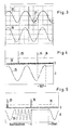
- 3 shows the output voltage of the control device 6 as the supply voltage 25.
- a voltage 26 is tapped via the coil 5. At the moment when the magnet 3 turns back against the normal direction of field rotation, it induces a signal 27.
- the evaluation device 14 has a subtractor 15, 16 for each coil 4, 5, the outputs of which are connected to an OR circuit 17.
- the inputs of the two subtractors are each supplied with voltages which have been scaled via a scaling device 13 such that the maximum values of the amplitudes of the vibrations supplied to the two inputs of the subtractors 15, 16 are the same.
- the scaling device has a bridge circuit for each coil 4, 5, one branch of which has a voltage divider with two ohmic resistors 41, 42 and 44, 45, while the other branch has an ohmic-inductive voltage divider consisting of coil 4 and ohmic resistor 43 or the coil 5 and the ohmic resistor 46.
- the voltage dividers and thus the bridge can be dimensioned such that, in the normal case, ie when the magnet 3 follows the field 19 unhindered, the same voltage drops across the coil 4 as across the ohmic resistor 42 or across the coil 5, the same voltage as across the resistor 45.
- the output of the subtractors 15, 16 is therefore approximately zero as a rule. This is shown in FIG. 4 using curve 28, which represents the output signal of subtractor 14. Only in the case where the rotor 2 turns back after the field has traveled 180 ° is a voltage induced in the coils 4, 5, which causes the voltage across the coils 4, 5 from the voltages across the resistors 41 , 44 deviates. A voltage pulse 29 is generated.
- This voltage pulse is greater than a predetermined limit value 35.
- a logic circuit 17 always generates a signal at its output when at least one of the subtractors 15, 16 generates a signal at its output that exceeds the threshold value 35. This ensures that every movement of the rotor 2 is recognized, even if a sufficiently large voltage is induced in only one of the two coils due to unfavorable geometric conditions.
- the logic circuit 17, which is therefore essentially constructed as an OR gate, supplies an output signal to the control logic 12. If the control logic 12 is implemented with the aid of a microprocessor, the output signal of the logic circuit 17 can be passed, for example, to an interrupt input of the microprocessor .
- the procedure of the display device is described with reference to FIG. 4.
- the signal generator 9 generates for each coil 4, 5 a step-shaped output signal 25 which, apart from the steps, is essentially sinusoidal. There is a short pause after each voltage change.
- the voltages for the two coils 4, 5 are 90 ° out of phase with one another.
- the rotor 2 can no longer turn.
- the field generated by the coils 4, 5 continues to rotate.
- the rotor 2 turns back against the direction of rotation of the field. Its magnet 3 induces a voltage.
- One of the two subtractors 15, 16 therefore generates an output signal 29.
- this output signal 29 is due to the fact that the rotor has rotated through 180 ° after reaching the stop (FIG. 2e) or whether it is only rotating has aligned with the field, which can happen when the arrangement is switched on (FIG. 2b), a further rotation of the field is carried out for safety reasons.
- the pointer then runs against the stop again and blocks the further rotation of the rotor. Only after the field has been rotated by a further 180 ° does the rotor jump back and generate a further pulse 30. 180 ° later in the voltage curve 25 is exactly the point in time at which the pointer 33 came to rest against the stop 24.
- a so-called learning phase is provided so that when a pulse occurs it can be said with certainty whether this pulse can be used to determine the absolute relationship between the pointer stop position and the position of the rotor in the motor .
- the rotor is moved in the learning phase so that the pointer is slowly moved twice against the stop.
- the real zero point ie the time in the course of the supply voltage or the electrical angle at which the pointer 33 is moved to the stop 24, is calculated and this zero point is stored in a non-volatile memory, for example an EEPROM.
- the zero point is different for each display device. Once the zero point has been determined, you can always use a correct zero point when starting. When starting, the exact current is set which has been determined to belong to the zero point. If the rotor now moves, you know that this signal is an error signal and can be ignored. This error signal is shown in FIG. 5 as signal 29. Only when the actual signal 30 occurs does one know that the pointer is in the stop position. The control logic 12 now waits a predetermined time before starting the actual display when the signal generator 9 is triggered again.
- the control voltage 25 of the control device 6 is built up in a step-like manner, a certain time passing between each individual step in which the current ratio of the coils 4, 5 is not changed. This time is sufficient to enable the rotor to reverse when the field has rotated more than 180 ° since the pointer was brought up to the stop.
- the control device 6 sets the magnetic field in the rotary field motor 1 to a new angle and waits for a certain time.
- the subtractors 15, 16 are then used to check whether a voltage spike 29, 30 has occurred. If this is not the case, a new angle is set. If this is the case, the motor was at the stop.
- the return phase is now complete.
- the absolute reference point has been established and a desired position can now be approached. The ad can start operating normally.
Abstract
Es wird ein Verfahren zum Bestimmen der absoluten Position eines Zeigers in einer Anzeigeeinrichtung angegeben, der von einem Rotor (2) eines Drehfeldmotors (1) über ein Getriebe (31) bewegt wird. Weiterhin wird eine Anzeigeeinrichtung angeben. Problematisch bei Anzeigeeinrichtungen mit Getriebe ist es, daß der absolute Bezug zwischen der Stellung des Zeigers (33) und der Stellung des Rotors (2) im Drehfeldmotor (1) nicht gegeben ist, wenn die Einrichtung gestartet wird und der Bezug verlorengegangen ist. Um den Bezug wieder herzustellen, wird der Zeiger (33) durch ein Drehfeld im Drehfeldmotor (1) in eine vorbestimmte Drehfeld-Richtung gegen einen Anschlag (34) bewegt. Das Drehfeld wird in der Drehfeld-Richtung weitergedreht. Ein durch eine Bewegung des Rotors (2) entgegen der Drehfeld-Richtung im felderzeugenden Teil (4, 5) des Drehfeldmotors induziertes Signal wird erfaßt, und aus der Winkelstellung des Drehfelds bei Auftreten des induzierten Signals wird die Winkelstellung des Rotors ermittelt, bei der der Zeiger am Anschlag anliegt. <IMAGE>The invention relates to a method for determining the absolute position of a pointer in a display device, which is moved by a rotor (2) of a rotating field motor (1) via a gear (31). A display device will also be specified. The problem with display devices with gearboxes is that the absolute relationship between the position of the pointer (33) and the position of the rotor (2) in the induction motor (1) does not exist when the device is started and the relationship has been lost. To restore the reference, the pointer (33) is moved by a rotating field in the rotating field motor (1) in a predetermined rotating field direction against a stop (34). The rotating field is rotated further in the rotating field direction. A signal induced by a movement of the rotor (2) against the rotating field direction in the field-generating part (4, 5) of the rotating field motor is detected, and the angular position of the rotor is determined from the angular position of the rotating field when the induced signal occurs The pointer rests on the stop. <IMAGE>
Description
Die Erfindung betrifft ein Verfahren zum Bestimmen der absuluten Position eines Zeigers in einer Anzeigeeinrichtung, der von einem Rotor eines Drehfeldmotors über ein Getriebe bewegt wird, und eine Anzeigeeinrichtung mit einem Zeiger, der über ein Getriebe vom Rotor eines Drehfeldmotors bewegt wird, und mit einem Anschlag für den Zeiger, wobei der Drehfeldmotor mindestens zwei felderzeugende Spulen aufweist, die mit einer Steuereinrichtung, die am Ausgang für jede Spule ein Signal erzeugt, elektrisch verbunden sind.The invention relates to a method for determining the absolute position of a pointer in a display device which is moved by a rotor of a rotating field motor via a gear, and a display device with a pointer which is moved by a rotor from a rotor of a rotating field motor and with a stop for the pointer, the rotating field motor having at least two field-generating coils, which are electrically connected to a control device that generates a signal at the output for each coil.
Im Gegensatz zu Anzeigeinstrumenten, in denen der Zeiger direkt von einem Rotor in einer Spulenanordnung beeinflußt wird, wie beispielsweise in einer Kreuzspul-Drehmagnetanordnung, ist es in einigen Anwendungsbereichen vorteilhaft, den Zeiger über ein Getriebe von einem Drehfeldmotor anzutreiben. In Abhängigkeit vom Übersetzungsverhältsnis des Getriebes muß der Rotor dann eine größere oder kleinere Anzahl von Umdrehungen durchführen, um den Zeiger um einen bestimmten Winkelbereich zu bewegen. Dem ansteuernden System ist es bekannt, wie viele Umdrehungen des Rotors notwendig sind, um die Anzeige um einen gewünschten Wert zu ändern. Dabei ist es jedoch von Nachteil, daß es keine direkte Beziehung mehr zwischen der Winkelposition des Rotors im Motor und der Stellung des Zeigers gibt. Jeder Winkelstellung des Rotors im Motor sind nämlich eine Vielzahl von Stellungen des Zeigers zugeordnet. Die absolute Position des Zeigers läßt sich also nicht mehr aus den Motordaten alleine ermitteln. Dies ist insbesondere dann von Nachteil, wenn die Energiezufuhr des ansteuernden Systems aus irgendeinem Grunde unterbrochen wird und das ansteuernde System die Information über die aktuelle Zeigerstellung verliert. Dies kann insbesondere bei der Verwendung der eingangs genannten Anzeigeeinrichtung in Kraftfahrzeugen der Fall sein, wo beispielsweise bei Reparaturen an der elektrischen Ausrüstung die elektrische Verbindung zur Batterie aus Sicherheitsgründen vollständig unterbrochen werden muß. Die Verwendung von externen Sensoren, beispielsweise induktiver Näherungsschalter, mechanischer Endschalter, Lichtschranken oder ähnliches verteuert die Anzeigeeinrichtung. Darüber hinaus bedeuten mehr Bauteile automatisch auch ein größeres Gewicht, was insbesondere bei Verwendung in der Kraftfahrzeug- oder Flugzeugtechnik unerwünscht ist. Außerdem steht oft nicht der Platz zur Verfügung, um die externen Sensoren unterzubringen.In contrast to display instruments in which the pointer is directly influenced by a rotor in a coil arrangement, such as, for example, in a cross-coil rotating magnet arrangement, it is advantageous in some areas of application to drive the pointer via a gearbox from a rotary field motor. Depending on the gear ratio of the gearbox, the rotor must then make a larger or smaller number of revolutions, to move the pointer through a certain angular range. The controlling system knows how many revolutions of the rotor are necessary to change the display by a desired value. However, it is disadvantageous that there is no longer a direct relationship between the angular position of the rotor in the motor and the position of the pointer. A large number of positions of the pointer are assigned to each angular position of the rotor in the motor. The absolute position of the pointer can therefore no longer be determined from the motor data alone. This is particularly disadvantageous if the energy supply to the actuating system is interrupted for some reason and the actuating system loses the information about the current pointer position. This can be the case in particular when using the display device mentioned at the beginning in motor vehicles, where, for example, the electrical connection to the battery must be completely interrupted for safety reasons when repairs are being carried out to the electrical equipment. The use of external sensors, for example inductive proximity switches, mechanical limit switches, light barriers or the like, makes the display device more expensive. In addition, more components automatically mean a greater weight, which is particularly undesirable when used in motor vehicle or aircraft technology. In addition, there is often not enough space to accommodate the external sensors.
Es ist die Aufgabe der Erfindung, ein Verfahren und eine Anzeigeeinrichtung anzugeben, mit denen ohne Einsatz von externen Sensoren der absolute Bezug zwischen dem ansteuernden System und der Zeigerstellung hergestellt werden kann.It is the object of the invention to provide a method and a display device with which the absolute relationship between the actuating system and the pointer position can be established without the use of external sensors.
Diese Aufgabe wird bei einem Verfahren der eingangs genannten Art dadurch gelöst, daß der Zeiger durch ein Drehfeld im Drehfeldmotor in eine vorbestimmte Drehfeldrichtung gegen einen Anschlag bewegt wird, das Drehfeld in der Drehfeld-Richtung weitergedreht wird, ein durch eine Bewegung des Rotors entgegen der Drehfeld-Richtung im felderzeugenden Teil des Drehfeldmotors induziertes Signal erfaßt wird und aus der Winkelstellung des Drehfeldes bei Auftreten des induzierten Signals die Winkelstellung des Rotors ermittelt wird, bei der der Zeiger am Anschlag anliegt.This object is achieved in a method of the type mentioned above in that the pointer is moved by a rotating field in the rotating field motor in a predetermined rotating field direction against a stop, the rotating field is rotated further in the rotating field direction, one by moving the rotor against the rotating field -Direction in the field-generating part of the rotating field motor induced signal is detected and the angular position of the rotor is determined from the angular position of the rotating field when the induced signal occurs, at which the pointer rests on the stop.
Die Erfindung beruhrt auf dem folgenden Prinzip: Wenn der Rotor eines Drehfeldmotors sich nicht mehr weiterdrehen kann, weil sein Ausgang blockiert ist, beispielsweise weil der Zeiger am Ausgang des Getriebes gegen einen Anschlag anliegt, und das ansteuernde Feld sich weiterbewegt, führt der Rotor eine Drehung entgegen der eigentlichen Drehrichtung des Feldes aus, wenn die Winkeldifferenz zwischen der Hauptachse des Rotors, die in der Regel durch einen Magneten gebildet wird, und der Hauptachse des Feldes größer als 180° wird. In diesem Fall "kippt" der Rotor aus einem labilen Gleichgewicht, das bei einer Winkeldifferenz von genau 180° auftritt, in ein stabiles Gleichgewicht, das bei einer Winkeldifferenz von 0° herrscht. Die beiden Hauptachsen von Rotor und Drehfeld kommen wieder zur Deckung. Durch die Bewegung des Rotors wird in der Spulenanordnung, die das Drehfeld erzeugt, ein Signal induziert. Dieses Signal kann beispielsweise als Spannung auftreten, die der erzeugenden Spannung entgegengesetzt ist. Dieses Signal kann dann ausgewertet werden. Da die Winkelstellung des Drehfeldes ah dem Zeitpunkt, an dem das Signal auftritt, bekannt ist, läßt sich die Anschlagglage des Zeigers dadurch errechnen, daß von dieser Winkelstellung 180° subtrahiert werden.The invention is based on the following principle: If the rotor of a rotating field motor can no longer rotate because its output is blocked, for example because the pointer is against a stop at the output of the transmission, and the driving field continues to move, the rotor rotates against the actual direction of rotation of the field if the angle difference between the main axis of the rotor, which is usually formed by a magnet, and the main axis of the field is greater than 180 °. In this case, the rotor "tilts" from an unstable equilibrium, which occurs at an angle difference of exactly 180 °, into a stable equilibrium, which prevails at an angle difference of 0 °. The two main axes of the rotor and the rotating field are again aligned. The movement of the rotor induces a signal in the coil arrangement that generates the rotating field. This signal can occur, for example, as a voltage that is opposite to the voltage that generated it. This signal can then be evaluated. Since the angular position of the rotating field ah at the time at which the signal occurs is known, the stop position of the pointer can be calculated by subtracting 180 ° from this angular position.
Das Drehfeld kann dabei kontinuierlich gedreht werden. Für eine bessere Auflösung ist es jedoch von Vorteil, daß das Drehfeld schrittweise gedreht wird. Das Signal, das durch den zurückdrehenden Rotor induziert wird, erscheint dann zwangsläufig nach einem bestimmten Schritt. Da das durch den Zeiger zurückgelegte Winkelinkrement für jeden Schritt bekannt ist, läßt sich die Subtraktion der 180° ganz einfach dadurch durchführen, daß eine bestimmte Anzahl von Schritten zurückgerechnet wird.The rotating field can be rotated continuously. For a better resolution, however, it is advantageous that the rotating field is rotated step by step. The signal that is induced by the rotating rotor then appears after a certain step. Since the angular increment covered by the pointer is known for each step, the subtraction of the 180 ° can be carried out very simply by recalculating a certain number of steps.
Zur Erhöhung der Auflösegenauigkeit ist es von Vorteil, daß zwischen jedem Schritt eine Pause vorwählbarer Länge vorgesehen ist. Der Rotor braucht naturgemäß eine gewisse Zeit, um sich zurückzudrehen. Diese Zeit ist unter anderem durch die Trägheit bestimmt, die der Rotor seiner Drehung entgegensetzt. Wenn nach jedem Schritt eine Pause eingelegt wird, hat der Rotor genügend Zeit, um sich zurückzudrehen und sich mit dem Feld auszurichten. Bei ausreichender Dimensionierung der Pausen kann es also nicht vorkommen, daß das Signal, daß die Rückdrehung des Rotors anzeigt, erst auftritt, wenn sich das Drehfeld schon zu weit, also um einen Winkel von weit mehr als 180°, weitergedreht hat.To increase the resolution accuracy, it is advantageous that a pause of a preselectable length is provided between each step. The rotor naturally takes a certain amount of time to turn back. This time is determined, among other things, by the inertia that the rotor opposes to its rotation. If there is a pause after each step, the rotor has enough time to turn back and align with the field. If the pauses are sufficiently dimensioned, it cannot occur that the signal indicating that the rotor is rotating back only occurs when the rotating field has already rotated too far, i.e. by an angle of far more than 180 °.
Mit Vorteil wird die Drehung des Drehfelds nach Auftreten des induzierten Signals fortgesetzt, und erst ein zweites oder späteres induziertes Signal wird zur Bestimung der absoluten Position des Zeigers verwendet. Wenn das System aus einem beliebigen Zustand gestartet wird, ist der Bezug des Magnetfeldes zur Winkellage des Rotors nicht definiert. Das Magnetfeld des Drehfeldmotors muß aber in einer bestimmten Lage eingeschaltet werden. Dieses zwangsweise Einstellen eines Winkels kann ein Ausgangssignal in der Spulenanordnung zur Folge haben, wenn beispielsweise die Winkellage des Rotors nicht mit der Winkellage des Feldes übereingestimmt hat. Um sicherzustellen, daß nicht irrtümlicherweise dieses Signal für die Ermittlung des Anschlag-Zustandes des Zeigers ausgewertet wird, ist erfindungsgemäß vorgesehen, daß erst das zweite oder ein späteres Signal verwendet wird, um festzustellen, ob der Rotor am Anschlag ist oder nicht. Auch wenn die Winkellage des Rotors zufälligerweise genau mit der eingestellten Winkellage des Drehfelds übereingestimmt hat, schadet die vorgeschlagene Verfahrenweise nicht. Der Rotor wird dann zwar gegen den Anschlag bewegt, und erzeugt nach der Drehung des Drehfeldes um etwas mehr als 180° ein erstes Signal, das theoretisch zur Bestimmung der Anschlag-Lage des Zeigers verwendet werden könnte. Der Rotor dreht sich dann weiter, wobei die Anschlag-Lage des Zeigers erst bei der zweiten Umdrehung tatsächlich bestimmt wird, weil erst der zweite Impuls "gültig" ist. Die geringe mechanische Belastung des Zeigers ist unerheblich.The rotation of the rotating field is advantageously continued after the occurrence of the induced signal, and only a second or later induced signal is used to determine the absolute position of the pointer. If the system is started from any state, the relationship of the magnetic field to the angular position of the rotor is not defined. However, the magnetic field of the rotary field motor must be switched on in a certain position. This forced setting of an angle can result in an output signal in the coil arrangement, if, for example, the angular position of the rotor did not match the angular position of the field. To ensure that this signal is not mistakenly evaluated for determining the stop state of the pointer, the invention provides that only the second or a later signal is used to determine whether the rotor is at the stop or not. Even if the angular position of the rotor coincidentally coincided exactly with the set angular position of the rotating field, the proposed procedure does no harm. The rotor is then moved against the stop, and generates a first signal after rotation of the rotating field by a little more than 180 °, which could theoretically be used to determine the stop position of the pointer. The rotor then continues to rotate, the stop position of the pointer actually being determined only at the second rotation, because only the second pulse is "valid". The low mechanical load on the pointer is irrelevant.
Für den zuletzt genannten Effekt kann es vorkommen, daß der Zeiger am Beginn des Bestimmungsvorganges zweimal kurzzeitig bewegt wird. Diese zweimalige Bewegung könnte störend auf das Auge eines Benutzers oder Betrachters wirken. Um diesen Nachteil zu beseitigen, ist erfindungsgemäß vorgesehen, daß in einer Lernphase die Winkellage des Drehfeldes, bei der das Signal induziert wird, ermittelt und nichtflüchtig abgespeichert wird, und daß am Angang einer Bestimmungsphase diese Winkellage des Drehfelds eingestellt wird. In der Lernphase wird der Zeiger zweimal langsam gegen den Anschlag gefahren, der reale Nullpunkt, d.h. die Winkellage des Drehfeldes bei der der Zeiger am Anschlag liegt, berechnet und dieser Wert abgespeichert, beispielsweise in einem nichtflüchtigen Speicher (EEPROM). Beim Starten des Systems, beispielsweise nach einem vollständigen Stromausfall, wird das Drehfeld auf den gespeicherten Wert eingestellt. Wird nach Anlegen dieses Wertes ein Signal durch eine Drehung des Rotors erzeugt, ist sichergestellt, daß es sich um ein Fehlersignal handelt und ignoriert werden kann.For the last-mentioned effect it can happen that the pointer is briefly moved twice at the beginning of the determination process. This double movement could interfere with the eye of a user or viewer. In order to eliminate this disadvantage, the invention provides that the angular position of the rotating field at which the signal is induced is determined and stored in a non-volatile manner in a learning phase, and that this angular position of the rotating field is set at the start of a determination phase. In the learning phase, the pointer is slowly moved twice against the stop, the real zero point, ie the angular position of the rotating field at which the pointer lies against the stop, is calculated and this value is stored, for example in a non-volatile memory (EEPROM). When starting the system, for example after a complete power failure, the rotating field is set to the saved value. If a signal is generated by turning the rotor after applying this value, it is ensured that it is an error signal and can be ignored.
Bei einer Anzeigeeinrichtung der eingangs genannten Art wird die Aufgabe dadurch gelöst, daß eine Auswerteschaltung vorgesehen ist, die die Signale am Ausgang der Steuereinrichtung mit den Signalen am Eingang der zugehörigen Spule vergleicht.In the case of a display device of the type mentioned at the outset, the object is achieved in that an evaluation circuit is provided which compares the signals at the output of the control device with the signals at the input of the associated coil.
Die Signale am Ausgang der Steuereinrichtung (Ausgangssignale) erzeugen in jeder Spule ein Magnetfeld. Die Überlagerung der Magnetfelder einer jeden Spule ergeben das resultierende Magnetfeld. Durch Änderung der Bestromungsverhältnisse in den einzelnen Spulen läßt sich die Richtung des resultierenden Magnetfelds ändern. Beispielsweise läßt sich ein Drehfeld dadurch erzeugen, daß die Steuereinrichtung für jede Spule ein sinusförmiges Ausgangssignal erzeugt, wobei die Ausgangssignale elektrisch um einen Winkel gegeneinander phasenverschoben sind, der dem räumlichen Winkel zwischen den einzelnen Spulen der Spulenanordnung entspricht. Die Sinus-Signale können natürlich auch treppen- oder stufenförmig aufgebaut sein, wenn sich der Rotor des Drehfeldmotors schrittweise bewegt. Die Auswerteeinrichtung untersucht nun, ob der Signalverlauf am Eingang der jeweiligen Spulen (Eingangssignale) mit den Ausganssignalen der Steuereinrichtung übereinstimmt. Dies wird grundsätzlich immer der Fall sein, ausgenommen wenn der Rotor sich zurückdreht, um sich wieder mit dem Feld auszurichten. In diesem Fall stimmt nämlich das Ausgangssignal der Steuereinrichtung nicht mehr mit dem Eingangssignal der zugehörigen Spule überein. Die Auswerteschaltung kann dann ein Signal erzeugen, das diese Nicht-Übereinstimmung anzeigt.The signals at the output of the control device (output signals) generate a magnetic field in each coil. The superimposition of the magnetic fields of each coil results in the resulting magnetic field. The direction of the resulting magnetic field can be changed by changing the current conditions in the individual coils. For example, a rotating field can be generated in that the control device generates a sinusoidal output signal for each coil, the output signals being electrically out of phase with one another by an angle which corresponds to the spatial angle between the individual coils of the coil arrangement. The sinusoidal signals can of course also be constructed in steps or steps if the rotor of the rotating field motor moves step by step. The evaluation device now examines whether the signal curve at the input of the respective coils (input signals) corresponds to the output signals of the control device. This will always be the case, except when the rotor turns back to align with the field. In this case, the output signal of the control device no longer corresponds to the input signal of the associated coil. The evaluation circuit can then generate a signal that indicates this mismatch.
Dazu weist die Auswerteschaltung vorteilhafterweise für jede Spule einen Subtrahierer auf, der die Differenz zwischen einer Spannung über der Spule und einer Spannung am zugeordneten Ausgang der Steuereinrichtug bildet. Diese Differenz folgt im Normalfall einer bestimmten Gesetzmäßigkeit. Wenn beide Spannungen eine Sinusform mit unterschiedlicher Amplitude aufweisen, ist die Differenzspannung ebenfalls sinusförmig, wobei die Amplitude der Amplitudendifferenz entspricht. Diese Gesetzmäßigkeit wird aber dann gestört, wenn der Rotor sich zurückdreht und eine zusätzliche Spannung in der Spule induziert.For this purpose, the evaluation circuit advantageously has a subtractor for each coil, which forms the difference between a voltage across the coil and a voltage at the associated output of the control device. This difference normally follows a certain law. If both voltages have a sinusoidal shape with different amplitudes, the differential voltage is also sinusoidal, the amplitude corresponding to the amplitude difference. However, this regularity is disturbed when the rotor turns back and induces an additional voltage in the coil.
Vorteilhafterweise ist dabei eine Skalierungseinrichtung vorgesehen, die die Amplitude der beiden Eingangsspannungen eines jeden Subtrahierers gleich groß macht. Die Differenz, die der Subtrahierer erzeugt, wird dann im Normalfall Null. Nur wenn sich der Rotor zurückdreht und eine Spannung induziert, erscheint am Ausgang des Subtrahierers eine von Null verschiedene Spannung.Advantageously, a scaling device is provided which makes the amplitude of the two input voltages of each subtractor the same size. The difference that the subtractor generates then normally becomes zero. Only when the rotor turns back and induces a voltage does a non-zero voltage appear at the output of the subtractor.
Bevorzugterweise weist dabei jede Skalierungseinrichtung zwei Spannungsteiler auf. Mit diesen Spannungsteilern läßt sich die Skalierungseinrichtung auf einfache Art und Weise realisieren.Each scaling device preferably has two voltage dividers. The scaling device can be implemented in a simple manner with these voltage dividers.
Dabei kann einer der beiden Spannungsteiler die zugehörige Spule und einen ohmschen Widerstand und der andere Spannungsteiler zwei ohmsche Widerstände aufweisen. Die Spannungsteilung mit Hilfe eines ohmschen bzw. eines ohmsch-induktiven Spannungsteilers ist ein einfaches Verfahren zur Skalierung der abgegriffenen Spannungen.One of the two voltage dividers can have the associated coil and an ohmic resistor and the other voltage divider can have two ohmic resistors. The voltage division using an ohmic or an ohmic-inductive voltage divider is a simple method for scaling the tapped voltages.
In einer bevorzugten Ausführungsform sind die Ausgänge der Subtrahierer mit einer Logikschaltung verbunden, die ein Ausgangssignal erzeugt, wenn das Signal mindestens eines Subtrahiererausgangs einen vorbestimmten Wert überschreitet. Wie oben dargestellt, ist der Ausgang des Subtrahierers in der Regel gleich Null. Nur wenn ein Signal auftritt, weil sich der Rotor zurückdreht, weicht die Spannung über der Spule von der Spannung am Ausgang der Steuereinrichtung ab. In diesem Fall erzeugt der Subtrahierer ein Ausgangssignal. Wenn mehrere Spulen vorhanden sind, wie dies bei einem Drehfeldmotor der Fall sein muß, kann es allerdings vorkommen, daß in einer der Spulen kein Signal oder nur ein sehr kleines, kaum meßbares Signal erzeugt wird. Um sicherzustellen, daß die Auswerteeinrichtung zuverlässig ein Signal erfaßt, ist die Logikschaltung vorgesehen, die bereits dann reagiert, wenn nur ein einer Spule ein Signal induziert wird.In a preferred embodiment, the outputs of the subtractors are connected to a logic circuit, which generates an output signal when the signal of at least one subtractor output exceeds a predetermined value. As shown above, the output of the subtractor is usually zero. Only when a signal occurs because the rotor turns back does the voltage across the coil deviate from the voltage at the output of the control device. In this case, the subtractor produces an output signal. If several coils are present, as is the case with a rotating field motor, it can happen that no signal or only a very small, barely measurable signal is not generated in one of the coils. In order to ensure that the evaluation device reliably detects a signal, the logic circuit is provided which already reacts when only a signal is induced in one coil.
Mit Vorteil weist die Steuereinrichtung einen digital arbeitetenden Signalgenerator auf. Die Steuereinrichtung kann daher sehr leicht eine treppenförmige Ausgangsspannung erzeugen.The control device advantageously has a digitally operating signal generator. The control device can therefore very easily generate a step-like output voltage.
Die Erfindung ist im folgenden anhand eines bevorzugten Ausführungsbeipiels in Verbindung mit der Zeichnung beschrieben. Darin zeigen:
- Fig. 1 eine Schaltungsanordnung einer Anzeigeeinrichtung,
- Fig. 2 verschiedene Stellungen des Rotors in bezug auf das Magnetfeld,
- Fig. 3 zwei Spannungsverläufe zur Darstellung des induzierten Signals,
- Fig. 4 zwei Spannungsverläufe, von denen einer den Ausgang eines Subtrahierers darstellt und
- Fig. 5 einen vollständigen Spannungsverlauf zur Ansteuerung eines Zeigers.
- 1 shows a circuit arrangement of a display device,
- 2 different positions of the rotor with respect to the magnetic field,
- 3 shows two voltage profiles to represent the induced signal,
- Fig. 4 shows two voltage profiles, one of which represents the output of a subtractor and
- Fig. 5 shows a complete voltage curve for driving a pointer.
Ein Drehfeldmotor 1 weist einen Rotor 2 auf, der einen Magneten 3 trägt. Der Magnet 3 ist überlicherweise ein Permanentmagnet, er kann jedoch auch als Elektromagnet ausgebildet sein. Der Rotor 2 des Drehfeldmotors 1 ist über eine Achse 32 mit einem Getriebe 31 verbunden. Am Ausgang des Getriebes 31 ist ein Zeiger 33 angeordnet, der über eine Skala 34 bewegbar ist. An einem Ende der Skala 34 befindet sich ein Anschlag 24, der den Nullpunkt oder eine andere ausgezeichnete Stellung des Zeigers markiert. Wird der Zeiger 33 gegen den Anschlag 24 bewegt, wird über das Getriebe 31 und die Achse 32 jede Bewegung des Rotors 2 in die gleiche Richtung blockiert. Weiterhin weist der Motor 1 zwei Spulen 4, 5 auf, deren Spulenachsen räumlich um 90° gegeneinander versetzt sind. Eine Steuereinrichtung 6 erzeugt für jede Spule 4, 5 eine Spannung, die der Spule 4 über ein Leitungspaar 7 und der Spule 5 über ein Leitungspaar 8 zugeführt werden. Dazu weist die Steuereinrichtung 6 einen Signalgenerator 9 auf, dessen Signale in einem Verstärker 10 durch Treibestufen 11 verstärkt werden. Der Signalgenerator 9 ist ein digitaler Signalgenerator, d.h. er erzeugt für jede Spule eine Abfolge von vorher festgelegten Spannungstufen. Die Spannungsdifferenz von Stufe zu Stufe kann variieren. Es kann dabei beispielsweise angestrebt werden, einen sinusförmigen Spannungsverlauf zu erreichen. Die Ausgangssignale des Signalgenerators 9 werden in einem Tiefpaßfilter 18 gefiltert. Am Ausgang der Steuereinrichtung 6 kann daher eine mehr oder weniger sinusförmige Spannung abgegriffen werden. Die Steuereinrichtung 6 weist eine Steuerlogik 12 auf, die den Signalgenerator 9 ansteuert. Die Steuerlogik 12 kann beispielsweise mit Hilfe eines Mikroprozessors realisiert sein.A rotating field motor 1 has a
Im Drehfeldmotor 1 wird durch eine unterschiedliche Bestromung der beiden Spulen 4, 5 ein drehendes Magnetfeld erzeugt. Dieses Magnetfeld ergibt sich aus der Überlagerung des von der Spule 4 erzeugten Magnetfeldes mit dem von der Spule 5 erzeugten Magnetfeldes. Die Richtung des Magnetfeldes richtet sich im wesentlichen nach dem Verhältnis der Bestromung der beiden Spulen 4, 5. Durch eine Ansteuerung mit zwei sinusförmigen Signalen, die um 90° elektrisch gegeneinander versetzt sind, läßt sich im Drehfeldmotor 1 ein Feld erzeugen, das beispielsweise entgegen dem Uhrzeigersinn umläuft, wie dies in Fig. 2 dargestellt ist. Bei Inbetriebnahme des Drehfeldmotors 1 wird willkürlich ein Bestromungsverhältnis und damit eine Magnetfeldrichtung eingestellt. Beispielsweise erhält nur die Spule 4 einen Strom, während die Spule 5 stromlos bleibt. Das resultierende Magnetfeld ist durch den Pfeil 19 dargestellt. Die Winkellage des Magneten 3 und des Rotors 2 werden damit in der Regel nicht übereinstimmen. Der Rotor 2 wird sich daher in Richtung des Pfeiles 20 drehen, so daß die Hauptrichtung, d.h. die Nord-Süd-Achse, des Magneten 3 mit der Hauptrichtung 19 des Magnetfeldes übereinstimmt. Das Magnetfeld dreht sich dann weiter in Richtung des Pfeiles 21, wobei der Magnet 3 in Richtung des Pfeiles 21′ läuft. Aus Gründen der Einfachheit ist nicht dargestellt, daß aufgrund der Belastung durch das Getriebe 31 eine gewisse Winkeldifferenz zwischen dem Magnetfeld 19 und dem Magneten 3 auftreten kann (Fig. 2c). Nach einer durch die Ausgangslage des Zeigers 33 und das Übersetzungsverhältnis des Getriebes 31 bestimmten Anzahl von Umdrehungen des Rotors 2 läuft der Zeiger 33 gegen einen Anschlag 24, so daß eine weitere Bewegung des Rotors 2 blockiert ist, wie dies in Fig. 2d schematisch dargestellt ist. Das Magnetfeld 19 dreht sich jedoch in Richtung des Pfeiles 22 weiter. Wenn das Magnetfeld sich um einen Winkel von 180° weitergedreht hat, sind die Polaritäten von Magnetfeld 19 und Magneten 3 genau entgegengesetzt. Der Magnet 3 befindet sich in einem labilen Gleichgewichtszustand. Wird nun das Magnetfeld 19 um einen kleinen Winkel weiter in die ursprüngliche Richtung gedreht, "kippt" der Magnet 3 und dreht sich entgegen der Umlaufrichtung des Magnetfeldes 19 zurück, um sich wieder mit dem Magnetfeld 19 auszurichten (Fig. 2e). Durch diese Bewegung induziert der Magnet 3 in den beiden Spulen 4, 5 eine Spannung, die der speisenden Spannung entgegengesetzt ist. In Fig. 3 ist als speisende Spannung 25 die Ausgangsspannung der Steuereinrichtung 6 dargestellt. Über die Spule 5 wird eine Spannung 26 abgegriffen. In dem Augenblick, wo sich der Magnet 3 entgegen der normalen Felddrehrichtung zurückdreht, induziert er ein Signal 27.A rotating magnetic field is generated in the rotating field motor 1 by different energization of the two coils 4, 5. This magnetic field results from the superposition of the magnetic field generated by the coil 4 with the magnetic field generated by the coil 5. The direction of the magnetic field depends essentially on the ratio of the current supply to the two coils 4, 5. By actuation with two sinusoidal signals which are electrically offset from one another by 90 °, a field can be generated in the rotating field motor 1, which, for example, counteracts the Rotates clockwise, as shown in Fig. 2. When the rotary field motor 1 is started up, an energization ratio and thus a magnetic field direction are arbitrarily set. For example, only the coil 4 receives a current, while the coil 5 remains de-energized. The resulting magnetic field is represented by
Dieses Signal wird in einer Auswerteeinrichtung 14 ausgewertet. Die Auswerteeinrichtung 14 weist für jede Spule 4, 5 einen Subtrahierer 15, 16 auf, deren Ausgänge mit einer ODER-Schaltung 17 verbunden sind. Die Eingänge der beiden Subtrahierer werden jeweils mit Spannungen versorgt, die über eine Skalierungseinrichtung 13 so skaliert worden sind, daß die Maximalwerte der Amplituden der den beiden Eingängen der Substrahierer 15, 16 zugeführten Schwingungen gleich sind. Die Skalierungseinrichtung weist für jede Spule 4, 5 eine Brückenschaltung auf, deren einer Zweig einen Spannungsteiler mit zwei ohmschen Widerständen 41, 42 bzw. 44, 45 aufweist, während der andere Zweig einen ohmsch-induktiven Spannungsteiler aus der Spule 4 und dem ohmschen Widerstand 43 bzw. der Spule 5 und dem ohmschen Widerstand 46 aufweist. Da die Betriebsfrequenz, mit der das Drehfeld umläuft, bekannt ist, lassen sich die Spannungsteiler und damit die Brücke so dimensionieren, daß im Normalfall, d.h. wenn der Magnet 3 dem Feld 19 ungehindert folgt, über die Spule 4 die gleiche Spannung abfällt wie über dem ohmschen Widerstand 42 bzw. über die Spule 5 die gleiche Spannung wie über den Widerstand 45. Der Ausgang der Subtrahierer 15, 16 ist also in der Regel annähernd gleich Null. Dies ist in Fig. 4 anhand der Kurve 28 dargestellt, die das Ausgangssignal des Subtrahierers 14 darstellt. Lediglich in dem Fall, wo der Rotor 2 sich zurückdreht, nachdem das Feld 180° zurückgelegt hat, wird in den Spulen 4, 5 eine Spannung induziert, die bewirkt, daß die Spannung über den Spulen 4, 5 von den Spannungen über den Widerständen 41, 44 abweicht. Es entsteht ein Spannungsimpuls 29. Dieser Spannungsimpuls ist größer als ein vorbestimmer Grenzwert 35. Eine Logikschaltung 17 erzeugt immer dann ein Signal an ihrem Ausgang, wenn mindestens einer der Subtrahierer 15, 16 an seinem Ausgang ein Signal erzeugt, das den Schwellwert 35 überschreitet. Damit wird sichergestellt, daß jede Bewegung des Rotors 2 erkannt wird, auch wenn aufgrund ungünstiger geometrischer Verhältnisse nur in einer der beiden Spulen eine ausreichend große Spannung induziert wird. Die Logikschaltung 17, die deswegen im wesentlichen als ODER-Glied aufgebaut ist, liefert ein Ausgangssignal an die Steuerlogik 12. Wenn die Steuerlogik 12 mit Hilfe eines Mikroprozessors realisiert ist, kann das Ausgangssignal der Logikschaltung 17 beispielsweise auf einen Interrupt-Eingang des Mikroprozessors geleitet werden.This signal is evaluated in an
Anhand von Fig. 4 wird die Verfahrensweise der Anzeigeeinrichtung beschrieben. Der Signalgenerator 9 erzeugt für jede Spule 4, 5 ein stufenförmiges Ausgangssignal 25, das, abgesehen von den Stufen, im wesentlichen sinusförmig ist. Nach jeder Spannungsänderung erfolgt eine kleine Pause. Die Spannungen für die beiden Spulen 4, 5 sind um 90° gegeneinander phasenverschoben. Zu einem bestimmten Zeitpunkt, nämlich dann, wenn der Zeiger 33 gegen den Anschlag 24 gefahren worden ist, kann sich der Rotor 2 nicht mehr weiterdrehen. Das Feld, das durch die Spulen 4, 5 erzeugt wird, dreht sich jedoch weiter. Wenn sich das Feld um weitere 180° gedreht hat, dreht sich der Rotor 2 entgegen der Felddrehrichtung zurück. Sein Magnet 3 induziert eine Spannung. Einer der beiden Subtrahierer 15, 16 erzeugt daher ein Ausgangssignal 29. Da man aber nicht sicher ist, ob dieses Ausgangssignal 29 daher rührt, daß sich der Rotor nach Erreichen des Anschlags um 180° gedreht hat (Fig. 2e) oder ob er sich nur nach dem Feld ausgerichtet hat, was beim Einschalten der Anordnung passieren kann (Fig. 2b), wird sicherheitshalber eine weitere Umdrehung des Feldes ausgeführt. Der Zeiger läuft dann wieder gegen den Anschlag und blockiert die weitere Drehung des Rotors. Erst nachdem das Feld um weitere 180° gedreht worden ist, springt der Rotor zurück und erzeugt einen weiteren Impuls 30. 180° später ist also im Spannungsverlauf 25 genau der Zeitpunkt an dem der Zeiger 33 an den Anschlag 24 zur Anlage gekommen ist.The procedure of the display device is described with reference to FIG. 4. The signal generator 9 generates for each coil 4, 5 a step-shaped
Um das zweimalige Bewegen des Rotors am Anschlag zu vermeiden, ist eine sogenannte Lernphase vorgesehen, um beim Auftreten eines Impulses sicher sagen zu können, ob dieser Impuls zur Bestimmung des absoluten Bezugs zwischen der Zeiger-Anschlagslage und der Stellung des Rotors im Motor verwenden werden kann. Dazu wird in der Lernphase der Rotor so bewegt, daß der Zeiger zweimal langsam gegen den Anschlag gefahren wird. Der reale Nullpunkt, d.h. der Zeitpunkt im Verlauf der Speisespannung bzw. der elektrische Winkel, bei dem der Zeiger 33 an den Anschlag 24 gefahren wird, wird berechnet und dieser Nullpunkt in einem nicht-flüchtigen Speicher, z.B. einem EEPROM, abgelegt. Da der Rotor in einer beliebigen Lage auf der Getriebewelle 32 aufgesteckt ist, d.h. kein exakter Bezug zwischen der Rotorausrichtung und der Zeigerbewegung besteht, ist der Nullpunkt für jede Anzeigeeinrichtung unterschiedlich. Wenn der Nullpunkt einmal ermittelt worden ist, kann man beim Starten jederzeit auf einen korrekten Nullpunkt zurückgreifen. Beim Starten wird genau die Bestromung eingestellt, die als zum Nullpunkt gehörig ermittelt worden ist. Wenn sich der Rotor nun bewegt, weiß man, daß dieses Signal ein Fehlersignal ist und ignoriert werden kann. Dieses Fehlersignal ist in Fig. 5 als Signal 29 dargestellt. Erst beim Auftreten des eigentlichen Signals 30 weiß man, daß der Zeiger sich in der Anschlagslage befindet. Die Steuerlogik 12 wartet nun eine vorbestimmte Zeit, bevor sie mit der erneuten Ansteuerung des Signalgenerators 9 die eigentliche Anzeige startet.In order to avoid moving the rotor twice at the stop, a so-called learning phase is provided so that when a pulse occurs it can be said with certainty whether this pulse can be used to determine the absolute relationship between the pointer stop position and the position of the rotor in the motor . For this purpose, the rotor is moved in the learning phase so that the pointer is slowly moved twice against the stop. The real zero point, ie the time in the course of the supply voltage or the electrical angle at which the
Wie insbesondere aus Fig. 4 ersichtlich, ist die Ansteuerungsspannung 25 der Steuereinrichtung 6 stufenförmig aufgebaut, wobei zwischen jeder einzelnen Stufe eine bestimmte Zeit verstreicht, in der das Bestromungsverhältnis der Spulen 4, 5 nicht geändert wird. Diese Zeit reicht aus, um dem Rotor eine Rückdrehung zu ermöglichen, wenn sich das Feld um mehr als 180° gedreht hat, seitdem der Zeiger an den Anschlag herangeführt worden ist. Die Steuereinrichtung 6 stellt das Magnetfeld im Drehfeldmotor 1 also auf einen neuen Winkel ein und wartet eine gewisse Zeit. Danach wird mit Hilfe der Subtrahierer 15, 16 überprüft, ob eine Spannungsspitze 29, 30 aufgetreten ist. Ist dies nicht der Fall, wird ein neuer Winkel eingestellt. Ist dies der Fall, befand sich der Motor am Anschlag. Die Rückführphase ist damit beendet. Der absolute Bezugspunkt ist hergestellt und eine gewünschte Position kann nun angefahren werden. Die Anzeige kann ihre normale Tätigkeit aufnehmen.As can be seen in particular from FIG. 4, the
Claims (12)
Applications Claiming Priority (2)
| Application Number | Priority Date | Filing Date | Title |
|---|---|---|---|
| DE3919926A DE3919926A1 (en) | 1989-06-19 | 1989-06-19 | METHOD FOR DETERMINING THE ABSOLUTE POSITION OF A POINTER IN A DISPLAY DEVICE AND DISPLAY DEVICE |
| DE3919926 | 1989-06-19 |
Publications (3)
| Publication Number | Publication Date |
|---|---|
| EP0407654A2 true EP0407654A2 (en) | 1991-01-16 |
| EP0407654A3 EP0407654A3 (en) | 1993-08-04 |
| EP0407654B1 EP0407654B1 (en) | 1995-02-22 |
Family
ID=6383015
Family Applications (1)
| Application Number | Title | Priority Date | Filing Date |
|---|---|---|---|
| EP89119662A Expired - Lifetime EP0407654B1 (en) | 1989-06-19 | 1989-10-24 | Indicator device and method of determining the absolute position of a pointer in the same |
Country Status (4)
| Country | Link |
|---|---|
| US (1) | US5055782A (en) |
| EP (1) | EP0407654B1 (en) |
| JP (1) | JPH0690054B2 (en) |
| DE (2) | DE3919926A1 (en) |
Families Citing this family (7)
| Publication number | Priority date | Publication date | Assignee | Title |
|---|---|---|---|---|
| DE4200551A1 (en) * | 1992-01-11 | 1993-07-15 | Vdo Schindling | SYNCHRONIZATION METHOD FOR A DISPLAY DEVICE WITH ELECTRICALLY CONTROLLED STEPPER MOTOR |
| DE4423119C1 (en) * | 1994-07-01 | 1995-12-14 | Moto Meter Gmbh | Procedure for zero positioning of a pointer |
| WO1999011999A1 (en) * | 1996-03-05 | 1999-03-11 | Harri Saario | Method and apparatus for measuring rotation motion |
| JP4509332B2 (en) * | 2000-08-09 | 2010-07-21 | 矢崎総業株式会社 | Stepper motor drive circuit |
| JP4718150B2 (en) * | 2003-10-29 | 2011-07-06 | カルソニックカンセイ株式会社 | Indicating instrument |
| DE102005021350A1 (en) * | 2005-05-04 | 2006-12-28 | Prefag Carl Rivoir GmbH & Co. Fabrik f. Präzisionsteile KG | measuring unit |
| DE102009056259B4 (en) * | 2009-11-28 | 2019-05-16 | Festo Ag & Co. Kg | measuring arrangement |
Citations (5)
| Publication number | Priority date | Publication date | Assignee | Title |
|---|---|---|---|---|
| DE2527744A1 (en) * | 1974-06-24 | 1976-01-15 | Gen Electric | ELECTRONICALLY COMMUTED MOTOR AND PROCESS FOR ITS MANUFACTURING |
| DE2946328A1 (en) * | 1978-11-21 | 1980-05-22 | Berney Sa Jean Claude | ANALOG DISPLAY DEVICE |
| DE3306642A1 (en) * | 1983-02-25 | 1984-09-13 | Licentia Patent-Verwaltungs-Gmbh, 6000 Frankfurt | Method for stepping the stator rotating field of a synchronous machine onwards |
| JPS60152298A (en) * | 1984-01-18 | 1985-08-10 | Hitachi Ltd | Rotation detector of step motor |
| JPH1126506A (en) * | 1997-06-30 | 1999-01-29 | Nec Kansai Ltd | Semiconductor device and manufacture |
Family Cites Families (3)
| Publication number | Priority date | Publication date | Assignee | Title |
|---|---|---|---|---|
| US3998179A (en) * | 1973-12-17 | 1976-12-21 | Dover Corporation | Apparatus for operating a pressure gauge or the like |
| US3977248A (en) * | 1975-04-03 | 1976-08-31 | Fischer & Porter Co. | Linearizing elements for variable area flowmeter |
| JPS5886405A (en) * | 1981-11-18 | 1983-05-24 | Nec Corp | Angle detector |
-
1989
- 1989-06-19 DE DE3919926A patent/DE3919926A1/en not_active Withdrawn
- 1989-10-24 DE DE58909039T patent/DE58909039D1/en not_active Expired - Lifetime
- 1989-10-24 EP EP89119662A patent/EP0407654B1/en not_active Expired - Lifetime
-
1990
- 1990-05-31 US US07/531,034 patent/US5055782A/en not_active Expired - Lifetime
- 1990-06-18 JP JP2157797A patent/JPH0690054B2/en not_active Expired - Lifetime
Patent Citations (5)
| Publication number | Priority date | Publication date | Assignee | Title |
|---|---|---|---|---|
| DE2527744A1 (en) * | 1974-06-24 | 1976-01-15 | Gen Electric | ELECTRONICALLY COMMUTED MOTOR AND PROCESS FOR ITS MANUFACTURING |
| DE2946328A1 (en) * | 1978-11-21 | 1980-05-22 | Berney Sa Jean Claude | ANALOG DISPLAY DEVICE |
| DE3306642A1 (en) * | 1983-02-25 | 1984-09-13 | Licentia Patent-Verwaltungs-Gmbh, 6000 Frankfurt | Method for stepping the stator rotating field of a synchronous machine onwards |
| JPS60152298A (en) * | 1984-01-18 | 1985-08-10 | Hitachi Ltd | Rotation detector of step motor |
| JPH1126506A (en) * | 1997-06-30 | 1999-01-29 | Nec Kansai Ltd | Semiconductor device and manufacture |
Non-Patent Citations (2)
| Title |
|---|
| PATENT ABSTRACTS OF JAPAN vol. 009, no. 321 (E-367)17 December 1985 & JP-A-60 152 298 ( HITACHI SEISAKUSHO KK ) 10 August 1985 * |
| PATENT ABSTRACTS OF JAPAN vol. 013, no. 370 (P-920)17 August 1989 & JP-A-11 26 506 ( SEIKO ELECTRONIC COMPONENTS ) 18 May 1989 * |
Also Published As
| Publication number | Publication date |
|---|---|
| EP0407654A3 (en) | 1993-08-04 |
| DE58909039D1 (en) | 1995-03-30 |
| DE3919926A1 (en) | 1990-12-20 |
| JPH0690054B2 (en) | 1994-11-14 |
| JPH0331722A (en) | 1991-02-12 |
| US5055782A (en) | 1991-10-08 |
| EP0407654B1 (en) | 1995-02-22 |
Similar Documents
| Publication | Publication Date | Title |
|---|---|---|
| DE102015121717B4 (en) | Electric power steering system for a vehicle | |
| EP1397277B8 (en) | Electric steering lock | |
| DE3019903C2 (en) | ||
| EP1615332B1 (en) | Method for operating an electronically commutated motor | |
| EP0582111B1 (en) | Inductive position sensor | |
| EP0014241B1 (en) | Method for the controlled steering of a d.c.-motor drive unit in a target position and circuit for implementing this method | |
| DE112005001683T5 (en) | Motor controller | |
| DE2612356A1 (en) | ANTI-LOCK REGULATOR FOR MOTOR VEHICLES | |
| DE102013218041A1 (en) | Method for operating an electric motor | |
| WO2001077693A1 (en) | Device for detecting the position and/or rotational speed and/or rotational direction of a rotating part | |
| EP0407654B1 (en) | Indicator device and method of determining the absolute position of a pointer in the same | |
| DE19511865C1 (en) | Setting element drive using electric stepping motor | |
| DE19612597A1 (en) | Stop and block detection in a stepper motor | |
| DE3832517C2 (en) | System for the electrical transmission of an angular position | |
| EP0403691A1 (en) | Method of detecting a predetermined pointer position and display device therefor | |
| DE19636267C2 (en) | Method for stopping a rotor mounted on a main shaft of a balancing machine and driven by an electric motor | |
| DE2717178A1 (en) | ELECTRONIC REAR DERAILLEUR | |
| DE1477698A1 (en) | Position control device | |
| DE2064679C3 (en) | Electronic distance measuring circuit | |
| DE4222949B4 (en) | Collectorless DC motor | |
| DE2742079B2 (en) | Drive arrangement for positioning a drive shaft | |
| DE761121C (en) | Device for synchronizing a coarse-fine transmission system | |
| DE942219C (en) | Arrangement for the remote control of objects with the help of control systems of synchronous design | |
| DE102011102629A1 (en) | Method for determining position of solenoid of steering locking device of vehicle, involves measuring reference time until preset minimum voltage of coil is reached after interrupting power supply | |
| DE2746356A1 (en) | AMPLITUDE-DEPENDENT SPEED SWITCH CONTROL |
Legal Events
| Date | Code | Title | Description |
|---|---|---|---|
| PUAI | Public reference made under article 153(3) epc to a published international application that has entered the european phase |
Free format text: ORIGINAL CODE: 0009012 |
|
| AK | Designated contracting states |
Kind code of ref document: A2 Designated state(s): DE FR GB IT SE |
|
| PUAL | Search report despatched |
Free format text: ORIGINAL CODE: 0009013 |
|
| AK | Designated contracting states |
Kind code of ref document: A3 Designated state(s): DE FR GB IT SE |
|
| 17P | Request for examination filed |
Effective date: 19930625 |
|
| 17Q | First examination report despatched |
Effective date: 19940203 |
|
| GRAA | (expected) grant |
Free format text: ORIGINAL CODE: 0009210 |
|
| AK | Designated contracting states |
Kind code of ref document: B1 Designated state(s): DE FR GB IT SE |
|
| PG25 | Lapsed in a contracting state [announced via postgrant information from national office to epo] |
Ref country code: IT Free format text: LAPSE BECAUSE OF FAILURE TO SUBMIT A TRANSLATION OF THE DESCRIPTION OR TO PAY THE FEE WITHIN THE PRE;WARNING: LAPSES OF ITALIAN PATENTS WITH EFFECTIVE DATE BEFORE 2007 MAY HAVE OCCURRED AT ANY TIME BEFORE 2007. THE CORRECT EFFECTIVE DATE MAY BE DIFFERENT FROM THE ONE RECORDED.SCRIBED TIME-LIMIT Effective date: 19950222 |
|
| ET | Fr: translation filed | ||
| REF | Corresponds to: |
Ref document number: 58909039 Country of ref document: DE Date of ref document: 19950330 |
|
| GBT | Gb: translation of ep patent filed (gb section 77(6)(a)/1977) |
Effective date: 19950328 |
|
| PLBE | No opposition filed within time limit |
Free format text: ORIGINAL CODE: 0009261 |
|
| STAA | Information on the status of an ep patent application or granted ep patent |
Free format text: STATUS: NO OPPOSITION FILED WITHIN TIME LIMIT |
|
| 26N | No opposition filed | ||
| REG | Reference to a national code |
Ref country code: FR Ref legal event code: CD |
|
| REG | Reference to a national code |
Ref country code: GB Ref legal event code: IF02 |
|
| PGFP | Annual fee paid to national office [announced via postgrant information from national office to epo] |
Ref country code: DE Payment date: 20081022 Year of fee payment: 20 |
|
| PGFP | Annual fee paid to national office [announced via postgrant information from national office to epo] |
Ref country code: SE Payment date: 20081014 Year of fee payment: 20 |
|
| PGFP | Annual fee paid to national office [announced via postgrant information from national office to epo] |
Ref country code: FR Payment date: 20081014 Year of fee payment: 20 |
|
| PGFP | Annual fee paid to national office [announced via postgrant information from national office to epo] |
Ref country code: GB Payment date: 20081021 Year of fee payment: 20 |
|
| REG | Reference to a national code |
Ref country code: GB Ref legal event code: PE20 Expiry date: 20091023 |
|
| EUG | Se: european patent has lapsed | ||
| PG25 | Lapsed in a contracting state [announced via postgrant information from national office to epo] |
Ref country code: GB Free format text: LAPSE BECAUSE OF EXPIRATION OF PROTECTION Effective date: 20091023 |